INSTALLATION INSTRUCTIONS
GMCT20 Cable
This guide describes how to connect and use the National Instruments GMCT20 cable, which has a maximum voltage rating of 300 V, CAT II. Use this cable to connect either the NI PXI-2585 or the NI PXI-2586 switch module to your application.
Caution Only use this cable with the NI PXI-2585 or NI PXI-2586 module.
The GMCT20 cable is available in two configurations:
• GMCT20-GMCT20
• GMCT20-BARE WIRE
Contents
Conventions ... 1
What You Need to Get Started ... 2
Getting Started with the GMCT20 Cable ... 2
Connectors ... 4
Cable Configurations ... 4
GMCT20-GMCT20 Cable... 4
GMCT20-BARE WIRE Cable ... 5
Specifications... 6
Environment... 6
Conventions
The following conventions are used in this guide:
» The » symbol leads you through nested menu items and dialog box options to a final action. The sequence File»Page Setup»Options directs you to pull down the File menu, select the
Page Setup item, and select Options from the last dialog box.
This icon denotes a caution, which advises you of precautions to take to avoid injury, data loss, or a system crash.
italic Italic text denotes variables, emphasis, a cross-reference, or an introduction to a key concept. Italic text also denotes text that is a placeholder for a word or value that you must supply.
monospace Text in this font denotes text or characters that you should enter from the keyboard, sections of code, programming examples, and syntax examples. This font is also used for the proper names of disk drives, paths, directories, programs, subprograms, subroutines, device names, functions, operations, variables, filenames, and extensions.
GMCT20 Cable Installation Instructions 2 ni.com
What You Need to Get Started
To use the cable, you need the following items:
❑
GMCT20 cable❑
NI PXI-2585 or NI PXI-2586 switch module and documentation❑
1/4 in. (0.6 cm) flathead screwdriverGetting Started with the GMCT20 Cable
Complete the following steps to connect the cable to the switch module and your application. Refer to Figures 1 through 3 for illustrations of the cable, and refer to Figure 4 for an illustration of the connector.
Caution Always de-energize hazardous voltage sources before connecting or disconnecting this cable.
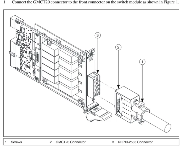
1. Connect the GMCT20 connector to the front connector on the switch module as shown in Figure 1.
Figure 1. Connecting the Cable to the NI PXI-2585
2. Tighten the screws on the cable with a 1/4 in. (0.6 cm) flathead screwdriver.
1 Screws 2 GMCT20 Connector 3 NI PXI-2585 Connector
NI PXI-2585 10x1 P ower Multiple xer 3 2 1
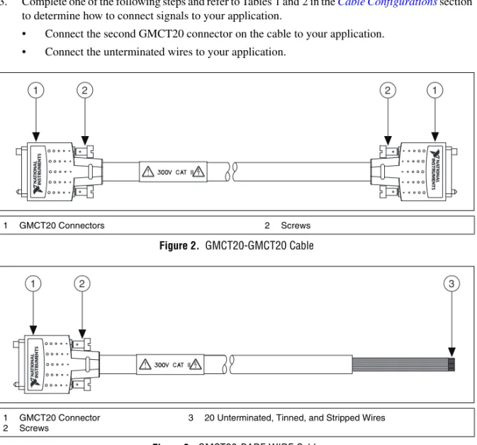
© National Instruments Corporation 3 GMCT20 Cable Installation Instructions 3. Complete one of the following steps and refer to Tables 1 and 2 in the Cable Configurations section
to determine how to connect signals to your application.
• Connect the second GMCT20 connector on the cable to your application. • Connect the unterminated wires to your application.
Figure 2. GMCT20-GMCT20 Cable
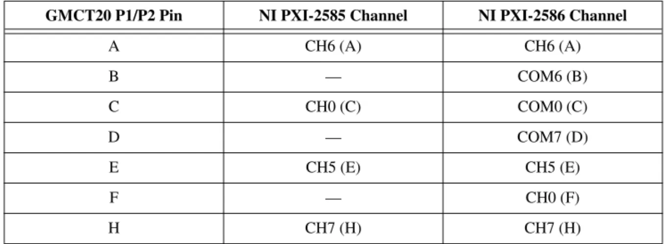
Figure 3. GMCT20-BARE WIRE Cable
1 GMCT20 Connectors 2 Screws
1 GMCT20 Connector 2 Screws
3 20 Unterminated, Tinned, and Stripped Wires
1 2 2 1
GMCT20 Cable Installation Instructions 4 ni.com
Connectors
The cable connects a 20-pin female Positronic GMCT connector (GMCT20 connector) to a second GMCT20 connector or twenty unterminated, tinned, and stripped wires. The GMCT20 connector provides connection to the switch module. The second GMCT20 connector and unterminated cables provide connection to your application. Figure 4 shows the pinout for the GMCT20 connector.
Figure 4. GMCT20 Mating Connector
Cable Configurations
The GMCT20 cable is available in two configurations:
• GMCT20-GMCT20
• GMCT20-BARE WIRE
The following sections describe each of the configurations.
GMCT20-GMCT20 Cable
The GMCT20-GMCT20 cable is recommended for connecting the switch module to your system.
Use the pinouts and the pin assignments listed in Table 1 to determine how to connect signals to your application using the GMCT20-GMCT20 cable.
Refer to the NI Switches Help for a complete listing of channel names and pinouts.
In the following table, letters in parentheses reference the pin designators of the connector.
Table 1. Pin Assignment for GMCT20-GMCT20 Cable
GMCT20 P1/P2 Pin NI PXI-2585 Channel NI PXI-2586 Channel
A CH6 (A) CH6 (A) B — COM6 (B) C CH0 (C) COM0 (C) D — COM7 (D) E CH5 (E) CH5 (E) F — CH0 (F) H CH7 (H) CH7 (H) PIN B PIN C PIN X PIN U PIN A PIN W
© National Instruments Corporation 5 GMCT20 Cable Installation Instructions
GMCT20-BARE WIRE Cable
The GMCT20-BARE WIRE cable is recommended for connecting the switch module to your system if termination other than a GMCT20 connector is required. One end of the cable terminates with a GMCT20 connector. The other end of the cable has twenty unterminated, tinned, and stripped wires.
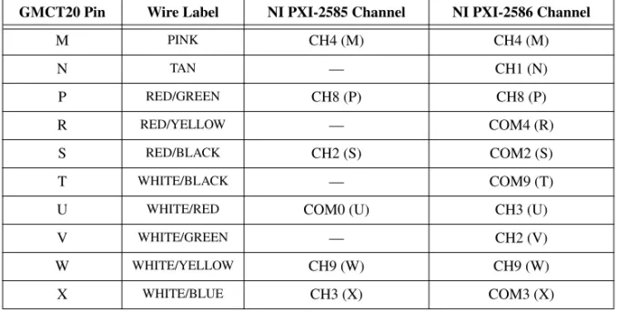
Use the pinouts and the pin assignments listed in Table 2 to determine how to connect signals to your application.
In the following table, letters in parentheses reference the pin designators of the connector.
J — COM5 (J) K CH1 (K) COM1 (K) L — COM8 (L) M CH4 (M) CH4 (M) N — CH1 (N) P CH8 (P) CH8 (P) R — COM4 (R) S CH2 (S) COM2 (S) T — COM9 (T)
U COM0 (U) CH3 (U)
V — CH2 (V)
W CH9 (W) CH9 (W)
X CH3 (X) COM3 (X)
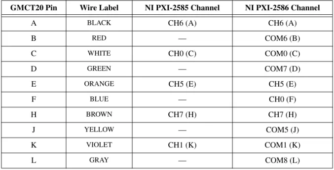
Table 2. Pin Assignment for GMCT20-BARE WIRE Cable
GMCT20 Pin Wire Label NI PXI-2585 Channel NI PXI-2586 Channel
A BLACK CH6 (A) CH6 (A)
B RED — COM6 (B)
C WHITE CH0 (C) COM0 (C)
D GREEN — COM7 (D) E ORANGE CH5 (E) CH5 (E)
F BLUE — CH0 (F)
H BROWN CH7 (H) CH7 (H)
J YELLOW — COM5 (J) K VIOLET CH1 (K) COM1 (K)
L GRAY — COM8 (L)
Table 1. Pin Assignment for GMCT20-GMCT20 Cable (Continued)
National Instruments, NI, ni.com, and LabVIEW are trademarks of National Instruments Corporation. Refer to the Terms of Use section on ni.com/legal for more information about National Instruments trademarks. Other product and company names mentioned herein are trademarks or trade names of their respective companies. For patents covering National Instruments products/technology, refer to the appropriate location: Help»Patents in your software, the patents.txt file on your media, or the National Instruments Patent Notice at ni.com/patents. © 2009 National Instruments Corporation. All rights reserved. 375861A Aug09
Specifications
Maximum voltage ...300 V, CAT II
Caution A total power load greater than 400 A2× channels will damage the GMCT20 cable under certain conditions. Refer to the NI PXI-2586 Specifications for example calculations and additional information about load derating.
Maximum current
Per channel...12 A
Simultaneous channelsat maximum current ...2 Weight
GMCT20-GMCT20 ...499 g (17.6 oz) GMCT20-BARE WIRE...748 g (26.4 oz)
Environment
Operating temperature ...0 °C to 55 °C
Storage temperature ...–20 °C to 70 °C
Relative humidity...5% to 85%, noncondensing
Pollution Degree ...2 Maximum altitude...2,000 m
Indoor use only.
M PINK CH4 (M) CH4 (M) N TAN — CH1 (N) P RED/GREEN CH8 (P) CH8 (P) R RED/YELLOW — COM4 (R) S RED/BLACK CH2 (S) COM2 (S) T WHITE/BLACK — COM9 (T)
U WHITE/RED COM0 (U) CH3 (U) V WHITE/GREEN — CH2 (V)
W WHITE/YELLOW CH9 (W) CH9 (W) X WHITE/BLUE CH3 (X) COM3 (X)
Table 2. Pin Assignment for GMCT20-BARE WIRE Cable (Continued)
取り付け手順
GMCT20
ケーブル
このガイドでは、最大電圧定格が300 V
、CAT II
のNI GMCT20
ケーブルの接続方法および 使用方法について説明します。このケーブルを使用してNI PXI-2585
またはNI PXI-2586
ス イッチモジュールをアプリケーションに接続します。 注意 このケーブルはNI PXI-2585
またはNI PXI-2586
モジュールとのみ使用してくだ さい。GMCT20
ケーブルには次の2
つの構成があります。• GMCT20-GMCT20
• GMCT20-BARE WIRE
目次
表記規則...1
使用を開始する前に...2
GMCT20
ケーブルを使用する...2
コネクタ...4
ケーブル構成...4
GMCT20-GMCT20
ケーブル...4
GMCT20-BARE WIRE
ケーブル...5
仕様...6
動作環境...6
表記規則
このドキュメントでは、以下の表記規則を使用します。 → 矢印(→)は、ネスト化されたメニュー項目やダイアログボックスのオプションをた どっていくと目的の操作項目を選択できることを示します。ファイル→ページ設定→ オプションと表記されている場合は、まずファイルメニューをプルダウンし、次に ページ設定項目を選択し、最後にダイアログボックスでオプションを選択します。 このアイコンは、人体への損傷やデータ損失、システムクラッシュなどを回避する ために必要な注意事項を示します。 斜体 斜体のテキストは、変数、強調、相互参照、または重要な概念の説明を示します。 また、斜体のテキストは、ユーザが入力する必要がある語句または値のプレースホ ルダも示します。 monospace このフォントのテキストは、キーボードから入力する必要があるテキストや文字、 コードの一部、プログラムサンプル、構文例を表します。また、ディスクドライブ、 パス、ディレクトリ、プログラム、サブプログラム、サブルーチンなどの名称、デ バイス名、関数、演算、変数、ファイル名および拡張子の引用にも使用されます。GMCT20ケーブル取り付け手順 2 ni.com/jp
使用を開始する前に
ケーブルを使用するには、以下が必要となります。❑
GMCT20
ケーブル❑
NI PXI-2585
またはNI PXI-2586
スイッチモジュールおよびドキュメント❑
1/4
インチ(0.6 cm
)マイナスドライバーGMCT20
ケーブルを使用する
ケーブルをスイッチモジュールおよびアプリケーションに接続するには次の手順に従いま す。ケーブルの取り付けについては図1
~3
を参照し、コネクタの図解は図4
を参照して ください。 注意 このケーブルの接続または接続解除を行う前に、必ず危険電圧のソースを切断し てください。1.
図1
に示すように、GMCT20
コネクタをスイッチモジュールのフロントコネクタに接 続します。 図1
ケーブルをNI PXI-2585
に接続する2. 1/4
インチ(0.6 cm
)マイナスドライバーを使用してネジを締めます。 1 ネジ 2 GMCT20コネクタ 3 NI PXI-2585コネクタ NI PXI-2585 10x1 P ower Multiple xer 3 2 1© National Instruments Corporation 3 GMCT20ケーブル取り付け手順
3.
次のいずれかの手順を実行し、「ケーブル構成」セクションの表1
および2
を参照して 信号をアプリケーションに接続する方法を確認します。•
ケーブルの2
つめのGMCT20
コネクタをアプリケーションに接続します。•
非終端ワイヤをアプリケーションに接続します。 図2 GMCT20-GMCT20
ケーブル 図3 GMCT20-BARE WIRE
ケーブル 1 GMCT20コネクタ 2 ネジ 1 GMCT20コネクタ 2 ネジ 3 20非終端、すずめっき、裸線 1 2 2 1 1 2 3GMCT20ケーブル取り付け手順 4 ni.com/jp
コネクタ
ケーブルを使用して20
ピンメスPositronic GMCT
コネクタ(GMCT20
コネクタ)を2
つ めのGMCT20
コネクタまたは20
本の非終端のすずめっき裸線に接続します。GMCT20
コ ネクタは、スイッチモジュールへの接続に使用します。2
つめのGMCT20
コネクタおよび 非終端ケーブルはアプリケーションへの接続に使用します。図4
は、GMCT20
コネクタの ピン配列を示します。 図4 GMCT20
メイトコネクタケーブル構成
GMCT20
ケーブルには次の2
つの構成があります。• GMCT20-GMCT20
• GMCT20-BARE WIRE
次のセクションでは、各構成について説明します。GMCT20-GMCT20
ケーブル
スイッチモジュールとシステムの接続にはGMCT20-GMCT20
ケーブルの使用が推奨され ています。 ピン配列および表1
のピン割り当て一覧を使用して、GMCT20-GMCT20
を使用したアプ リケーションへの信号接続方法を確認します。 チャンネル名およびピン配列の一覧については、『NI
スイッチヘルプ』を参照してください。 次の表の括弧内の文字はコネクタのピン識別子を示しています。 表1 GMCT20-GMCT20
ケーブルのピン割り当てGMCT20 P1/P2
ピンNI PXI-2585
チャンネルNI PXI-2586
チャンネルA
CH6 (A)
CH6 (A)
B
—
COM6 (B)
C
CH0 (C)
COM0 (C)
D
—
COM7 (D)
E
CH5 (E)
CH5 (E)
F
—
CH0 (F)
䊏䊮B 䊏䊮C 䊏䊮X 䊏䊮U 䊏䊮A 䊏䊮W© National Instruments Corporation 5 GMCT20ケーブル取り付け手順
GMCT20-BARE WIRE
ケーブル
GMCT20-BARE WIRE
ケーブルは、GMCT20
コネクタ以外の終端が必要な場合のスイッチ モジュールとシステム間の接続に推奨されています。ケーブルの一端はGMCT20
コネクタ で終端されます。ケーブルのもう一端は、20
本の非終端のすずめっき裸線です。 ピン配列および表2
のピン割り当て一覧を使用して、アプリケーションへの信号接続方法 を確認します。 次の表の括弧内の文字はコネクタのピン識別子を示しています。H
CH7 (H)
CH7 (H)
J
—
COM5 (J)
K
CH1 (K)
COM1 (K)
L
—
COM8 (L)
M
CH4 (M)
CH4 (M)
N
—
CH1 (N)
P
CH8 (P)
CH8 (P)
R
—
COM4 (R)
S
CH2 (S)
COM2 (S)
T
—
COM9 (T)
U
COM0 (U)
CH3 (U)
V
—
CH2 (V)
W
CH9 (W)
CH9 (W)
X
CH3 (X)
COM3 (X)
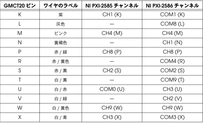
表2 GMCT20-BARE WIRE
ケーブルのピン割り当てGMCT20
ピン ワイヤのラベルNI PXI-2585
チャンネルNI PXI-2586
チャンネルA
黒CH6 (A)
CH6 (A)
B
赤—
COM6 (B)
C
白CH0 (C)
COM0 (C)
D
緑—
COM7 (D)
E
オレンジCH5 (E)
CH5 (E)
F
青—
CH0 (F)
H
茶CH7 (H)
CH7 (H)
J
黄色—
COM5 (J)
表1 GMCT20-GMCT20
ケーブルのピン割り当て(続き)GMCT20 P1/P2
ピンNI PXI-2585
チャンネルNI PXI-2586
チャンネルNational Instruments、NI、ni.com、およびLabVIEWはNational Instruments Corporation
(米国ナショナルインスツルメンツ社)の商標です。National Instrumentsの商標の詳細については、
ni.com/legalの「Terms of Use」セクションを参照してください。本文書中に記載されたその他の
製品名および企業名は、それぞれの企業の商標または商号です。National Instrumentsの製品/技術を保 護する特許については、ソフトウェアで参照できる特許情報(ヘルプ→特許情報)、メディアに含まれてい
るpatents.txtファイル、または「National Instruments Patent Notice」(ni.com/patents)のうち、
該当するリソースから参照してください。
© 2009 National Instruments Corporation. All rights reserved. 375861A-01 2009年8月
仕様
最大電圧...300 V
、CAT II
注意400 A
2をチャンネル数で乗算した値が合計電力負荷を上回ると、特定の条件下で はGMCT20
ケーブルが破損します。計算例および負荷の低下については、『NI PXI-2586
仕様』を参照してください。 最大電流 チャンネルあたり...12 A
最大電流で同時に使用可能なチャンネル数...2
重量GMCT20-GMCT20...499 g
(17.6 oz
)GMCT20-BARE WIRE ...748 g
(26.4 oz
)動作環境
動作温度...0
~55
℃ 保管温度...–20
~70
℃ 相対湿度...5
~85%
(結露なきこと) 汚染度...2
最大使用高度...2,000 m
室内使用のみ。K
紫CH1 (K)
COM1 (K)
L
灰色—
COM8 (L)
M
ピンクCH4 (M)
CH4 (M)
N
黄褐色—
CH1 (N)
P
赤/緑CH8 (P)
CH8 (P)
R
赤/黄色—
COM4 (R)
S
赤/黒CH2 (S)
COM2 (S)
T
白/黒—
COM9 (T)
U
白/赤COM0 (U)
CH3 (U)
V
白/緑—
CH2 (V)
W
白/黄色CH9 (W)
CH9 (W)
X
白/青CH3 (X)
COM3 (X)
表