Study on Titanium Dioxide Nanocrystals with
Specific Crystal Facet on Surface for High
Performance Photocatalyst and Dye-Sensitized
Solar Cells
Changdong Chen
Japan
December 2014
Kagawa University
Contents
CHAPTER I
General Introduction ... 1
1.1. Crystal Structures and Physical Properties of Titanium Dioxide Polymorphs ···2
1.2. Photocatalytic Reactions of Titanium Dioxides and Their Applications ···6
1.2.1. Photocatalytic Reactions Mechanism ···6
1.2.2. Visible Light Active Photocatalysis of TiO2 ··· 10
1.2.3. Application of Photocatalysis to Decomposition of H2O and Organic Pollution ··· 11
1.3. Dye-Sensitized Solar Cells ··· 12
1.3.1. Structure and Principle of Dye-Sensitized Solar Cell ··· 13
1.3.2. Materials for Dye-Sensitized Solar Cell ··· 15
1.3.3. Performance Characteristic Parameters and Equivalent Circuit of DSSC · 16 1.4. Titanium Dioxide Nanocrystals for Dye-Sensitized Solar Cell ··· 19
1.5. Synthesis of Anatase Titanium Dioxides with Specific Facet on Surface and Their Photocatalytic Activities ··· 21
1.5.1. Surface Structures of {101}, {010}, {001}, and {111} Facets of Anatase 24 1.5.2. Synthesis of Anatase TiO2 Nanoparticles with Specific Facet on the Surface ··· 25
1.5.3. Photocatalytic and DSSCs Performances of Anatase Titanium Dioxides with Specific Facet on the Surface ··· 27
1.6. Layered Titanate Compounds ··· 29
1.7. Microwave Hydrothermal Process for Synthesis of Titanium Dioxides ··· 31
1.8. Purposes of Present Study ··· 33
CHAPTER II
Synthesis of Titanium Dioxide Nanocrystals from H1.07Ti1.73O4 Layered Titanate
Nanosheets by Normal Hydrothermal Process and Their Dye-Sensitized Solar
Cell Performance ... 46
2.1. Introduction ··· 46
2.2. Experimental Section ··· 49
2.2.1. Preparation of Layered Titanate Nanosheet Colloidal Solutions ··· 49
2.2.2. Preparation of TiO2 Nanoparticles from PA-HTO Solution ··· 50
2.2.3. Preparation of TiO2 Nanoparticle Paste and TiO2 Photoelectrodes ··· 50
2.2.4. Fabrication and Characterization of Dye-Sensitized Solar Cell ··· 51
2.2.5. Adsorption of N719 Dye on TiO2 Nanoparticles ··· 52
2.2.6. Physical Analysis ··· 52
2.3. Results and Discussion ··· 53
2.3.1. Synthesis of TiO2 Nanoparticles from PA-HTO Nanosheet Solution ··· 53
2.3.2. TEM Study on PA-HTO Nanosheets and TiO2 Nanoparticles ··· 58
2.3.3. Transformation Reaction Mechanism from PA-HTO Nanosheets to TiO2 Nanocrystals ··· 60
2.3.4. DSSC Performance of {010}-Faceted TiO2 Nanoparticles ··· 63
2.3.5. N719 Dye Adsorption Behavior on TiO2 Nanocrystals with Different Facets on Surfaces ··· 65
2.3.6. Effect of Crystal Facets on DSSC Performance ··· 69
2.3.7. Effect of Light-Scattering Layer on DSSC Performance··· 73
2.4. Conclusion ··· 74
2.5. References ··· 75
Synthesis of Titanium Dioxide Nanocrystals from H1.07Ti1.73O4 Layered Titanate
Nanosheets by Microwave Hydrothermal Process for High Performance
Photocatalyst and Dye-Sensitized Solar Cells ... 79
3.1. Introduction ··· 79
3.2. Experimental Section ··· 82
3.2.1. Preparation of HTO Layered Titanate Nanosheet Colloidal Solutions ··· 82
3.2.2. Microwave Hydrothermal Treatment of PA-HTO Solution ··· 82
3.2.3. Photocatalytic Characterization ··· 83
3.2.4. Fabrication and Characterization of Dye-Sensitized Solar Cells··· 84
3.2.5. Physical Analysis ··· 85
3.3. Results and Discussion ··· 85
3.3.1. Microwave-Assisted Conversion of HTO Nanosheets to TiO2 Nanocrystals ··· 85
3.3.2. Nanostructural Study on Conversion Reaction from HTO Nanosheets to TiO2 Nanocrystals ··· 93
3.3.3. Electronic Band Structure and Photocatalytic Response of TiO2 Nanocrystals ··· 97
3.3.4. DSSCs Performance of TiO2 Nanocrystals ··· 103
3.4. Conclusion ··· 105
3.5. References ··· 106
CHAPTER IV Synthesis of [111]- and {010}-Faceted Anatase TiO2 Nanocrystals from Tri-Titanate Nanosheets and Their Photocatalytic and DSSCs Performances ... 110
4.1. Introduction ··· 110
4.2.1. Preparations of Na2Ti3O7 and H2Ti3O7 Samples ··· 112
4.2.2. Preparation of H2Ti3O7 Nanosheet Colloidal Solution and TiO2 Nanocrystals ··· 113
4.2.3. Photocatalytic Characterization ··· 114
4.2.4. Fabrication and Characterization of Dye-Sensitized Solar Cells··· 114
4.2.5. Physical Analysis ··· 116
4.3. Results and Discussion ··· 116
4.3.1 Preparations of Tri-Titanate H2Ti3O7 Nanosheet Solution ··· 116
4.3.2. Synthesis of TiO2 Nanocrystals from TMA-HTO Nanosheet Colloidal Solution ··· 120
4.3.3. Nanostructural Study of TiO2 Nanocrystals and Transformation Reaction Mechanism from TMA-HTO Nanosheets to TiO2 Nanocrystals ··· 124
4.3.4. Electronic Band Structure and Photocatalytic Activity of TiO2 Nanocrystals ··· 130
4.3.5. DSSC Performance of [111]-Faceted TiO2 Nanocrystals ··· 135
4.4. Conclusion ··· 138 4.5. References ··· 138 CHAPTER V Summary ... 143 PUBLICATIONS ... 148 ACKNOWLEDAMENT ... 151
CHAPTER I
General Introduction
The energy sources consumption is always one of the challenges that the mankind faces. With a constantly increasing population and improved daily living standard, more and more energy sources are needed. The main energy sources used today are the fossil fuels, such as coal, oil, and natural gas. However, the fossil fuels have two main disadvantages, one is the environmental pollution, and the other is non-renewable. To solve these problems, a large number of studies are proceeding to develop clean and sustainable energy sources. The solar energy which radiates light and heat from the sun, such as solar heating, solar photovoltaics, solar thermal energy, and artificial photosynthesis, attracts considerable attentions due to a range of clean and sustainable characteristics. Today the most used solar cell is silicon based solar cell. However, the high quality silicon materials for the solar cells are high cost and heavy pollution in making process. The dye-sensitized solar cell (DSSC) base on the titanium dioxide (TiO2) materials attracts considerable attentions about its potentially
low cost, relatively high energy conversion efficiency, safety, and non-pollution. The titanium dioxide (TiO2) is excellent photovoltaic and photocatalytic materials. The
synthesis processes of high photovoltaic and photocatalytic performance TiO2 are
related to technologies of chemistry, physics, material, chemical engineering and so on.
In this chapter, a general introduction for the TiO2 functional materials, including
the crystal structure and physical properties of TiO2, photocatalytic reactions of TiO2
nanocrystals and their applications, the DSSC system and the application of TiO2
layered titanate compounds, and the microwave hydrothermal process. Furthermore, the purposes of this dissertation are clarified.
Figure 1.1. Crystal structures of (a) rutile phase, (b) anatase phase, (c) brookite phase,
and (d) TiO2-B phase.
1.1. Crystal Structures and Physical Properties of Titanium Dioxide Polymorphs
As an excellent functional material, a large number of studies have been carried out on the structures, physical and chemical properties, and applications of titanium dioxide (TiO2) materials. And seven kinds of the TiO2 polymorphs have been reported
as far as we know.1-6 There are four kinds of the main polymorphs, rutile, anatase, brookite, and TiO2-B, which were found in nature. Furthermore, the TiO2-ІІ and
TiO2-ІІІ polymorphs are occasionally occurred in nature, and mostly synthesized at
high pressure process.4 The TiO2-H and TiO2-R polymorphs are metastable phases,
conversion reactions.5, 6
In recent years, the more and more studies have related on rutile and anatase polymorphs. They have a coincident basic blocks consist of the TiO6 octahedron,
where a titanium atom occupies at the center of the TiO6 octahedron, which is
constituted with six of the oxygen atoms.7, 8 The difference of anatase and rutile crystal structures is caused by the distortion level of each TiO6 octahedron and the
assembly pattern of the each octahedron chains. The crystal structures of the main four TiO2 polymorphs are shown in Figure 1.1. In the rutile structure, the TiO6
octahedron is not regular, which shows a slight distortion.7 And the each TiO6
octahedron contacts with ten neighbor TiO6 octahedrons, where two sharing edge
oxygen atoms and eight sharing corner oxygen atoms as shownin Figure 1.1(a). The Ti-Ti bond lengths are 0.357 nm and 0.296 nm, the Ti-O bond lengths are 0.195 nm and 0.198 nm in the rutile structure.2 In the anatase structure, the TiO6 octahedron of
constituent structure is significantly distorted and the each TiO6 octahedron contacts
with neighbor eight TiO6 octahedrons as shown in Figure 1.1(b), in which four sharing
corner oxygen atoms and four sharing edge oxygen atoms, respectively. And the Ti-Ti bond lengths are 0.379 nm and 0.304 nm, which are bigger than that of rutile phase, the Ti-O bond lengths are 0.193 nm and 0.198 nm, which are smaller than that of rutile phase in the anatase structure.1, 9 Moreover, in the crystal structure of the brookite phase, the TiO6 octahedrons share both edges and corners, forming an
orthorhombic structure as shown in Figure 1.1(c).10, 11 The Ti-Ti bond lengths are 0.295 nm and 0.306 nm, the Ti-O bond lengths are 0.196 nm in the brookite structure.12 And the TiO2-B has a monoclinic structure, which is composed of
corrugated sheets of edge- and corner-sharing TiO6 octahedrons as shown in Figure
Figure 1.2. XRD patterns of rutile, anatase, and brookite phases.
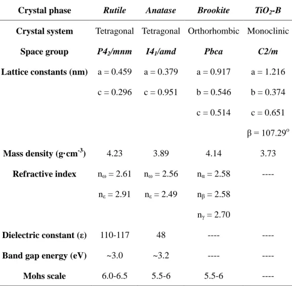
The structural parameters of the main TiO2 polymorphs, rutile, and anatase,
brookite, and TiO2-B phases are summarized in Table 1.1. The diffraction techniques,
including X-ray powder diffraction (XRD) and selected area electron diffraction (SAED), are important and useful method for the structural studies of the TiO2
powder samples. The typical XRD patterns of rutile, anatase, and brookite phases are shown in Figure 1.2. The rutile phase with tetragonal crystal system has characteristic diffraction peaks of (110), (101), (200), (111), (210), (211), and (220). The anatase phase with tetragonal crystal system exhibits diffraction peaks of (101), (103), (004), (112), (200), (105), and (211). The brookite phase with orthorhombic system has many diffraction peaks and the main peaks are (210), and (111), and (210). Furthermore, TiO2-B phase belong to monoclinic system, which exhibits the main
Table 1.1. Structural parameters and physical properties of main TiO2 phases.
Crystal phase Rutile Anatase Brookite TiO2-B
Crystal system Tetragonal Tetragonal Orthorhombic Monoclinic
Space group P42/mnm I41/amd Pbca C2/m
Lattice constants (nm) a = 0.459 c = 0.296 a = 0.379 c = 0.951 a = 0.917 b = 0.546 c = 0.514 a = 1.216 b = 0.374 c = 0.651 β = 107.29o Mass density (g·cm-3) 4.23 3.89 4.14 3.73 Refractive index nω = 2.61 nε = 2.91 nω = 2.56 nε = 2.49 nα = 2.58 nβ = 2.58 nγ = 2.70 ---- Dielectric constant (ε) 110-117 48 ---- ----
Band gap energy (eV) ~3.0 ~3.2 ---- ----
Mohs scale 6.0-6.5 5.5-6 5.5-6 ----
The different crystal structures of the TiO2 polymorphs causes their different
physical and chemical properties, such as mass densities, stabilities, thermodynamic properties, electronic band structure, dielectric constant and so on.15-20 The some physical and chemical properties are shown in Table 1.1. Rutile is a thermodynamic stable phase, and anatase is metastable phase which transforms to the rutile phase above 600 oC. The mass density, refractive index, dielectric constant, and mohs scale of rutile phase are larger than which of anatase phase. And the band gap energy of rutile phase is smaller than that of the anatase phase.21, 22, 23, 24
1.2. Photocatalytic Reactions of Titanium Dioxides and Their Applications
Since Fujishima and Honda reported a breakthrough research of photocatalytic water splitting on TiO2 with the UV-light irradiating in 1972, the heterogeneous
photocatalysis has been a focus of considerable attention.25, 26 After that, a large number of studies have been reported on the photocatalytic reactions and their applications. In this section, a review on the photocatalytic reactions of TiO2 and their
applications is given.
1.2.1. Photocatalytic Reactions Mechanism
The phenomenon of heterogeneous photocatalysis occur when a semiconductor (photocatalyst) is irradiated by visible or UV light. The semiconductor has a void region called bandgap which extends from the top of the filled valence band (VB) to the bottom of the vacant conduction band (CB). When the semiconductor is irradiated under visible or UV light with light energy equal to or greater than its bandgap energy (Eg), an electron (e-) is excited from the VB to the CB, and a hole (h+) is created in the
VB. The excited electron in CB and created hole in VB can act as reductant and oxidant, respectively, and they can cause redox reaction on the semiconductor surface. Such photochemical reaction is called photocatalytic reaction and the semiconductor acts as photocatalyst in the reaction.25-30
Figure 1.3. Schematic illustrating of the photocatalytic reactions on a semiconductor
in heterogeneous photocatalysis.
A more detailed photocatalytic reaction process is illustrated in Figure 1.3. When the photocatalyst absorbs the irradiated visible or UV light, the e--h+ pairs (exciton) can be generated in the photocatalyst. The excited electron in CBcan transfer to the photocatalyst surface (pathway A), and reduce an electron acceptor adsorbed on the surface, such as oxygen in an aerated solution. The O2 adsorbed on the surface can be
reduced to superoxide (O2−), and then O2− can further react with other species. The
generated hole in VBalso can migrate to the photocatalyst surface (pathway B), and combine with an electron from an electron donor species, and oxidize the donor species adsorbed on the photocatalyst surface. For example, the holes can oxidize OH- adsorbed on the surface to ·OH radical in an aqueous solution, and then the ·OH radical formed can further react with other species. Furthermore, the excited e- and generated h+ can recombine on the photocatalyst surface and inside of the photocatalyst (pathway C). And also the excited e- and generated h+ can be trapped by
the lattice defect of photocatalyst crystal, and then recombine together.31
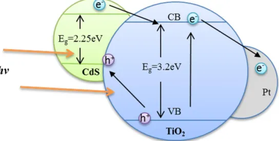
Therefore, the inhibition of the e--h+ charge recombination and promoting the charge separation are effective to enhance the photocatalytic efficiency. The decreasing crystal defect or increasing crystallinity of the photocatalyst is an effective method to diminish the charge recombination. The surface modification with metals (Pt, Au, Ag, etc.) or semiconductors (CdS, CdSe, etc.) can promote the charge separation as shown in Figure 1.4, where the excited electrons can transfer to the metal side and generated hole to the semiconductor side. Since the photocatalytic reactions occur on the photocatalyst surface, the enlargement of photocatalyst surface area can enhance also enhance the photocatalytic efficiency.32-35
Figure 1.4. Schematic illustrating the charge separation process by the TiO2 surface
modification with metal (Pt) and semiconductor (CdS).
The redox potentials of photogenerated electrons and holes at photocatalyst are depended on the bandgap energy positions of the photocatalyst. The relationship between the band energy level and redox potential of electrochemical reaction is shown in Figure 1.5 to illustrate the thermodynamic limitations of the redox reactions that can be carried out with photogenerated electrons and holes.31 The photogenerated
electrons by the photocatalyst can reduce thermodynamically an electron acceptor species, if the reduction potential of the acceptor species locates below the conduction band of the photocatalyst. If the oxidation potential of an electron donor species locates above the valence band of the photocatalyst, the photogenerated holes can oxidize the donor species thermodynamically.
Figure 1.5. Band-edges and positions of valence band and conduction band of several
semiconductors in contact with chemical reduction potential (NHE), and the H2/H2O
and O2/H2O reduction potentials in an aqueous solution at pH 1.
The TiO2 is n-type semiconductor materials. Similar to other semiconductor
materials, TiO2 can absorb light whose energy is equal or larger than the bandgap
energy of TiO2, and lead to inject the electrons from the valence band to the
conduction band. The anatase phase and rutile phase have slightly different bandgap energies of 3.2 and 3.0 eV, which correspond to the wavelength of absorbance band edges of 410 and 393 nm, respectively. The band energy levels of anatase and rutile are also different as given in Figure 1.5. The bandgap energy and band-edge position are dependent not only on chemical composition, but also on the structure.36-40 The TiO2 polymorphs exhibit different photocatalytic behavior because they have different
highest photocatalytic activity.41
1.2.2. Visible Light Active Photocatalysis of TiO2
The bandgap energies of TiO2 polymorphs indicate that the UV light with a
wavelength less 410 or 393 nm is necessary for photocatalytic reactions on anatase or rutile, but it only has 4% of UV light in the solar spectrum contains. It means the efficiencies of photocatalytic reactions of the TiO2 polymorphs are low on the sun
light irradiating conditions. Therefore, the development of visible light active TiO2
photocatalyst is significant in the viewpoint of exploitation of solar energy because of the more than 90% sunlight energy is in visible light region. The main method is shifting absorption threshold of TiO2 semiconductor towards visible region. The
doping technology of TiO2 semiconductor has been reported for the preparation of
visible light active TiO2 photocatalyst, such as metal element doped TiO2
semiconductor (Nd3+, Cr3+, Fe3+, Co2+, V5+),42-45 non-metal element doped TiO2
semiconductor (N),46-57 and oxygen vacancy TiO2 semiconductor.58-60
Figure 1.6. Schematic diagram of an electrochemical photocell developed by Fujishima and Honda. (1) n-type TiO2 electrode; (2) platinum black counter electrode;
voltmeter.
1.2.3. Application of Photocatalysis to Decomposition of H2O and Organic
Pollution
The photodecomposition of H2O effect is similar with the photosynthesis of plants.
The plants can obtain the energy and produce oxygen through oxidizing H2O and
reducing CO2 with sunlight.25, 26 On the basis of the principle of photosynthesis,
Fujishima and Honda have found that H2O can be split using the TiO2 semiconductor
material with the UV-light irradiating.25 The device of splitting H2O is shown in
Figure 1.6. The TiO2 electrode and the platinum (Pt) counter electrode are connected
with an electrical load. Once the UV light with light consisting of wavelengths shorter than 415 nm irradiates on the surface of the TiO2 electrode, the photogeneration e- can
flow to the Pt electrode from the TiO2 electrode through the external circuit. In other
words, the photocurrent flows from the Pt counter electrode to the TiO2 electrode
through the external circuit. This process is very similar with electrochemical decomposition of water, and the distinction is the process of electrochemical decomposition of H2O needs to add an electric potential difference of more than 1.23
V between anodic electrode and cathodic electrode, and the photodecomposition of H2O process needs to absorb UV light with wavelength less than about 400 nm. The
direction of the photocurrent expounds that an oxidation reaction can occur at the TiO2 electrode and a reduction reaction can occur at the Pt electrode, and the oxygen
and hydrogen can be obtained from this process. The photodecomposition reaction of H2O can accord to the following reaction mechanism from (1.1) to (1.4).26
TiO2 + 2hv → 2h+ + 2e- (excitation of TiO2 by UV light)···················· (1.1)
H2O + 2h+ → (1/2)O2 + 2H+ (at the TiO2 electrode)···················· (1.2)
2H+ + 2e- → H2 (at the Pt electrode)···················· (1.3)
Frank and Bard have reported the photodecomposition of cyanide in solution by TiO2 suspension, and it starts the new direction to aiming at apply TiO2 photocatalysis
to decompose the organic pollution, such as the photocatalytic decompositions of aldehydes, carboxylic acids, chlorophenols, dyes, phenolics, ethers, ketones and so on. In this photocatalytic reaction, the organic pollution can be decomposed by the oxidation reaction. The various forms of active oxygen like O2−, HO2·, ·OH, ·O, and
H2O2 can be produced.61-66 These active oxygen species have fortissimo oxidizability
and most of organic pollution can be essentially oxidized completely to CO2.
1.3. Dye-Sensitized Solar Cells
In 1991, a new type of photovoltaic cell fabricated by using dye sensitized effect, which is known as a dye-sensitized solar cell (DSSC), has be developed by Grӓtzel group. This DSSC can successfully convert visible light energy to electrical energy and achieve 7.9% solar energy conversion efficiency, and the incident photon to electrical current conversion efficiency is nearly 80%.67 After that, a larger number of intensive studies on DSSCs have been carried out among chemistry, physics, material, chemical engineering and so on,68-80 and the highest conversion efficiency of DSSC has been renewed about 12.3%.81 Many kinds of excellent factors led the DSSC to gained extensive attentions, such as low production cost, flexibility, lightweight, transparency, multicolor options, and indoor applications. 82-84
1.3.1. Structure and Principle of Dye-Sensitized Solar Cell
Figure 1.7. Schematic structure of a typical dye-sensitized solar cell.
A typical DSSC is composed of three main parts: the dye sensitized TiO2 electrode,
the liquid electrolyte containing I3-/I- redox couple, and the platinum (Pt) electrode
with sandwich structure as shown in Figure1.7.67 The dye sensitized TiO2 electrode
usually composes of a sintered TiO2 film on conducting glass coated with
fluorine-doped tin oxide (FTO), the thickness of sintered TiO2 film is around 10 µm,
and the porosity of film is around 50-60%.67, 85 A photosensitizer with the anchoring groups (-COOH) can be anchored onto the TiO2 nanoparticle surface. After photo
exciting, the oxidized photosensitizer can be restored to ground state by electron transfer in the liquid electrolyte containing the I3-/I- redox couple. Furthermore, the
formed I3- ions can be reduced to I- ions on the cathode with a coated platinum
catalyst. 65, 84-87 To achieve the best performance, the charge transfer resistance of platinum electrode is less than 1Ω·cm-2.88
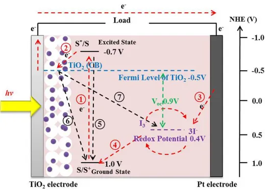
The operation principle of DSSC is shown in Figure 1.8, where the desired pathways of the electron transfer processes are described as path ○1 to ○4 . When the
-can be excited from the ground state to excited state of dye as the path ○1 , and the
photogenerated hole can be left to form a oxidized dye. And then the photogenerated e- can inject into the conduction band of TiO2 as the path ○2 , and then the
photogenerated e- can be collected on the FTO substrate through the TiO2 film. The
collected photogenerated e- can transfer to the platinum counter electrode through outside circuit as the path ○3 . In the meantime, the oxidized dyes on the TiO2
electrode can be regenerated by 3I- from the electrolyte as the path ○4 . And 3I- is then
further regenerated at the Pt electrode through the reduction of I3- by the
photogenerated e-. Furthermore, the photogenerated e- loss processes are described as path ○5 to ○7 . The photogenerated e- can recombine with the hole in the oxidized
dye as the path ○5 . The photogenerated e- injected into the conduction band of TiO2
can also recombine with the hole in the oxidized dye as the path ○6 and with the
electron acceptors of I3- ions in the electrolyte as the path ○7 , respectively. Usually,
we call these photogenerated e- loss processes as the back current, and it degrades the performance of DSSC.65, 89-93
For the photogenerated e- can transfer from dye to TiO2 semiconductor, successfully,
the potential of electronically excited state (S*) needs lower than the potential of CB of TiO2 semiconductor.Furthermore, the maximum output photovoltage of the solar
cell corresponds to the difference between Fermi level of semiconductor and the redox potential of electrolyte, which can be expressed by equation (1.5).
Vmax = EFn – EF0 ···················· (1.5)
Where the Vmax value is the maximum output photovoltage, the EFn value is Fermi
level of semiconductor, and EF0 value is the redox potential of electrolyte,
respectively. For TiO2 semiconductor and I3-/I- redox pair, the maximum output
photovoltage or largest open-circuit photovoltage (Voc) is about 0.9 V.94
1.3.2. Materials for Dye-Sensitized Solar Cell
A large improvement in DSSCs in 1991 is the use of a mesoporous TiO2 electrode
with a high surface area in internal TiO2 electrode.67 The high surface area of
mesoporous TiO2 electrode can adsorb more dye molecules on the surface in order to
improve the efficiencies. The TiO2 nanocrystal materials for DSSC will be described
in detail in Section 1.4. Except TiO2 nanocrystal materials, other metal oxide materials
and ternary oxides, such as ZnO, Nb2O5, SnO2 and Zn2SnO4, also have been tested for
the dye-sensitized electrode.95-98
Another important material in DSSC is the sensitizer, which can adsorb sun-light and provide the photogenerated electrons for DSSC system.99, 100 The sensitizer for DSSC should satisfy several basic characteristics: (1) the sensitizer should be able to absorb the sun-light with the whole visible region and even the part of the near-IR, it means the absorption spectrum of the sensitizer should be lower than the wavelength of near-IR (920 nm); (2) the sensitizer should have the anchoring groups such as
-COOH and -H2PO3 and be able to strongly anchor on the TiO2 nanoparticle surface;
(3) the excited state level of the sensitizer should be higher than the conduction band edge of the TiO2 in energy, and determine the photogenerated electrons can inject into
conduction band of the TiO2 from the excited dye; (4) the oxidized state level of the
sensitizer should be more positive than the redox potential of electrolyte for regeneration process of the sensitizer; (5) the sensitizer should be stable at electrochemical and thermal reaction process. Based on these conditions, many different types of sensitizers have been designed and developed, such as metal complexes, porphyrins and phthalocyanines, and organic dyes.
Furthermore, the electrolyte and counter electrode are also the important parts in DSSC. The electrolyte can collect electrons at counter electrode and regenerate the sensitizer as described above; the commonly used electrolytes include liquid redox electrolytes, gel and polymer electrolytes, and ionic liquid electrolytes.100-104 And the counter electrode are usually prepared by sprayed and heated platinum on the conducting glass substrate surface. Moreover, carbon materials, cobalt sulfide, and conducting polymers are also used to prepare the counter electrode.100
1.3.3. Performance Characteristic Parameters and Equivalent Circuit of DSSC
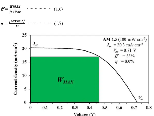
There are four main characteristic parameters, short-circuit photocurrent density (Jsc), open-circuit photovoltage (Voc), fill factor (ff), and photoelectric power
conversion efficiency (η) for the characterization of solar cells performance. These parameters can be evaluated from the photocurrent-voltage characteristic curve of the solar cells as shown in Figure 1.9. The short-circuit photocurrent density is a current density without any external applied voltage, namely current density in the short electric circuit system or maximum current density of the solar cell. The open-circuit
photovoltage is a voltage in the open circuit system, namely maximum voltage of the solar cell. The maximum Voc of DSSC corresponds to the difference between Fermi
level of semiconductor and the redox potential of electrolyte. The fill factorprovides an easy comparison for the performance of a solar cell compared to the theoretical maximum performance. The ff value can be calculated by equation (1.6), and the photoelectric power conversion efficiency (η) can be calculated by equation (1.7), where the WMAX value is the maximum output power and Is value is the intensity of
the incident light, respectively. Therefore, enhancements of Jsc, Voc, and ff are
important to enhance solar cell performance η.67, 105 ff = 𝑾𝑴𝑨𝑿𝑱𝒔𝒄·𝑽𝒐𝒄 ···················· (1.6)
η = 𝑱𝒔𝒄·𝑽𝒐𝒄·𝒇𝒇𝑰𝒔 ···················· (1.7)
Figure 1.9. A typical photocurrent-voltage characteristic curve of solar cell and
relations between the photocurrent-voltage characteristics and cell parameters.
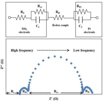
The electrochemical impedance spectrum (EIS) can be used to measure and analyze internal resistance in DSSC.106-110 An equivalent circuit and a typical impedance spectrum of DSSC are shown in Figure 1.10. In the equivalent circuit, Rs
is electron transport resistance in the circuit, Rrc and C1 represent the charge transfer
resistance in the charge recombination process and the chemical capacitance of the TiO2 film and electrolyte interface, respectively, RD is the diffusion resistance of
electrolyte, and RPt and C2 are the charge transfer resistance and the interface
capacitance of Pt and electrolyte interface. Small values of Rs, RD, and RPt, and large
value of Rrc can improve the DSSC performance. The typical impedance spectrum of
DSSC shows a linear feature and three semicircles, respectively. In this spectrum, with decreasing the frequency, firstly a linear feature corresponding Rs, a small
semicircle resulting from RPt and C2, a big semicircle due to Rrc and C1, and then a
small semicircle resulting from RD are observed. Therefore the parameters of Rs, RPt,
Rrc, C1 and C2 can be evaluated from the impedance spectrum. Usually the semicircle
corresponding to RD cannot be observed even in the very low-frequency region such
as until to 0.1 Hz.
Figure 1.10. Equivalent circuit and a typical impedance spectrum of a dye-sensitized
1.4. Titanium Dioxide Nanocrystals for Dye-Sensitized Solar Cell
As described above, the dye sensitized TiO2 electrode is a most significant part in
DSSC system. The dye sensitized TiO2 electrode is fabricated by coating a conducting
glass plate with TiO2 nanoparticles, and adsorbing dye molecules on the TiO2
nanoparticle surface. Therefore, the performance of dye sensitized TiO2 electrode is
strongly affected by the properties of the TiO2 nanoparticles. The structure, particle
size and morphology, crystallinity, crystal facet exposing on the surface of the TiO2
nanoparticles can influence the DSSC performance similar to their photocatalytic activity.111-113 Usually it is considered that anatase nanoparticles exhibit higher performance that rutile particles. Although the anatase phase and rutile phase are all constructed with the TiO6 octahedron and have a tetragonal lattice system, they show
the different DSSC performance and photocatalytic reactivity. Because of the different connection type of these TiO6 octahedrons and the surface atomic and electronic
structures are revealed in the crystal system.64
And another reason is that anatase nanoparticles with size less than 30 nm are difficult to be synthesized. The high performance TiO2 electrode has a double-layer
structure as shown in Figure 1.11. The nanocrystalline TiO2 layer is fabricated using
TiO2 with particle size less 30 nm and the optimum layer thickness is about 10 µm.
The nanocrystalline TiO2 layer is mesoporous layer that provide a large TiO2 surface
area for adsorption of large amount of dye molecules on the dye sensitized electrode, and also increase of the contacting area between the dye molecules and the liquid electrolyte. The increases dye loading amount causes enhancement of the efficiency of sun light harvesting. Therefore, usually the anatase nanoparticles with the size of less than 30 nm are selected. Since the nanocrystalline TiO2 layer has higher transmittance,
lower sun light harvesting. To solve this problem, the nanocrystalline TiO2 layer is
coated by a light-scattering layer fabricated using TiO2 particles with a size of about
400 nm. This layer can reduce the transmission loss of light.114, 115
Figure 1.11. Structures of (a) single-layer and (b) double-layer TiO2 mesoporous
electrodes for DSSC.
The crystallinity of the TiO2 nanocrystals also can affect the efficiency of DSSC;
because of high crystallinity of the TiO2 nanocrystal can reduce the probability of
captured photogenerated electrons into the defect of the TiO2 nanocrystal.82
Furthermore, the effect of morphology of the TiO2 nanocrystals on the DSSC
performance has been studied using spherical nanoparticles, nanorods, nanowires, nanosheets, and nanotubes.116 The effect of enlarging electron conductivity of the TiO2 mesoporous electrode using nanorod and nanowire improves the DSSC
performance. In recent years, the effect of crystal facet exposing on TiO2 nanocrystal
surface has been reported.117 It indicate that the different facets exposing on TiO2
nanocrystal surface can affect the behavior of the dye molecules adsorption, which can affect the efficiency of DSSC.
1.5. Synthesis of Anatase Titanium Dioxides with Specific Facet on Surface and Their Photocatalytic Activities
Since Fujishima and Honda have reported the photocatalytic reactions of TiO2 to
split H2O under the UV-light irradiating in 1972,25 andGrӓtzel group has reported the
high performance DSSC in 1991,67 a large number of studies have been the focus of considerable attention on TiO2 and their applications. These studies refer to
application range of chemistry, physics, material, chemical engineering and so on in order to optimize the photocatalytic reactivity and DSSCs performance. As described above, the TiO2 has two main phases of anatase and rutile, and the anatase phase is
more suitable for the photocatalyst and DSSCs than the rutile phase.64 Usually, the sol-gel processes are used to the synthesis of anatase TiO2 nanoparticles. The titanium
salts are firstly hydrolyzed in solution, and the products are recrystallized.118 However, the reaction temperature range is limited; therefore crystal size and morphology are not easy to be controlled through the sol-gel processes. The hydrothermal process is another method to prepare TiO2 nanoparticles, which can synthesize TiO2
nanoparticles under high temperature and pressure conditions above 100oC and 1 atm from a precursor.119 In recent years, more and more studies have reported to synthesize TiO2 nanoparticles by hydrothermal process. The anatase, rutile, and
brookite particles can be synthesized using the hydrothermal and solvothermal processes.120-122 The hydrothermal and solvothermal soft chemical processes are also effective for synthesis and particle morphology control of anatase nanoparticles from layered titanate compounds.
Recently, the synthesis of anatase nanoparticles with specific crystal facet on the particle surface has become a hot topic in the photocatalytic and DSSC studies. The crystal facet on the surface strongly affects the photocatalytic activity and dye
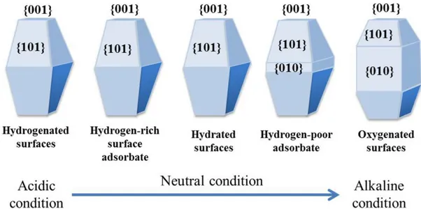
molecule adsorption due to different surface energies, arrangements of the atoms on surface, and electronic structures. Wulff et al. have constructed the crystal morphology model of anatase and predicted to the percentage of {101} facet on the crystal surface is about 94% in a normal anatase nanoparticle due to that the {101} facet is a thermodynamic stable facet with low surface energy.123 Furthermore, they have calculated to the surface energy of different facets in an order of {101} (0.44 J·m-2) < {010} (0.53 J·m-2) < {001} (0.90 J·m-2). The large number of studies has started after this theoretical study of surface energy. Barnard et al. have studied carefully the effects of surface energy and predicted the morphology of anatase nanoparticles in the acidic and alkaline conditions as shown in Figure 1.12.124 As a result, the {101}, {010} and {001} facet can be shown on nanoparticle surface in different of acidic and alkaline conditions. This result is quite important to synthesize experimentally the specific facet on nanoparticle surface based on surface chemical principle.
Figure 1.12. Predicted morphology of anatase nanoparticles in acidic and alkaline
conditions.
TiO2 nanoparticle with high surface energy of the {010} facet on the surface from a
lepidocrocite-like H1.07Ti1.73O4 layered titanate nanosheets by hydrothermal reaction,
and found that {010}-faceted anatase TiO2 nanoparticles exhibit higher photocatalytic
activity than the normal spherical nanocrystals without specific facet on the nanoparticle surface in 2007.111 The results spur researchers to study the synthesis of TiO2 nanocrystals with specific facet. And then Yang et al. have synthesized high
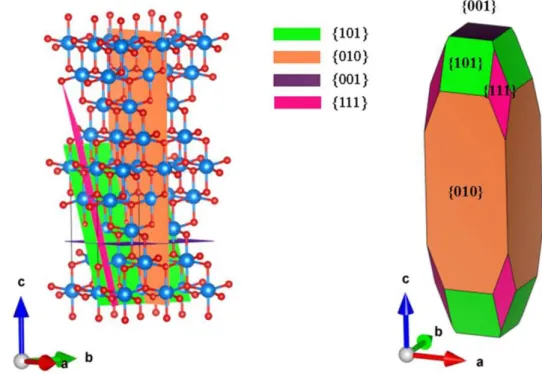
percentage of {001}-faceted anatase nanoparticles using hydrothermal method in a hydrofluoric acid solution in 2008.112 Furthermore, their results of first-principle quantum chemical calculation reveals that the {001} facet of anatase is one of reactive facets for the photocatalytic reactions. Very recently, Xu et al. have calculated the surface energy of {111} facet and resulted that the {111} facet (1.61 J·m-2) has higher surface energy than the {010} facet (0.90 J·m-2) in 2013,125 they also have given a schematic illustration of {101}, {010}, {001} and {111} facet in anatase structure and these facets on anatase nanoparticle surface as shown in Figure 1.13.
Figure 1.13. Schematic illustration of {101}, {010}, {001}, and {111} facets of
1.5.1. Surface Structures of {101}, {010}, {001}, and {111} Facets of Anatase
Figure 1.14. Surface structures of {101}, {010}, {001}, and {111} facets.
The surface structures of {101}, {010}, (001), and {111} are illustrated in Figure 1.14. As described above, the {101} facets have the low surface energy, the surface of bulk-terminated {101} facets expose unsaturated Ti5c and saturated Ti6c titanium
atoms as well as O2c and O3c oxygen atoms. Because of the anatase TiO2 is the
tetragonal system, the bulk-terminated {010} and {100} facets have the same surface structure, which expose unsaturated Ti5c titanium atoms, O2c and O3c oxygen atoms.
Comparing with the {101} facets, high percentage of Ti5c titanium atoms on the {010}
surface results in a higher surface energy than the {101} facets. The {001} facets expose unsaturated Ti5c titanium atoms, O2c and O3c oxygen atoms on the surface. As
the same with the {010} facets, the unsaturated Ti5c and O2c atoms can lead the facets
to have high surface energy of 0.90 J·m-2. The surface of {111} facets have the unsaturated Ti5c and Ti3c atoms. Xu et al. have used the density functional theory
(DFT) to calculate surface energy of anatase, and gave the surface energies for {101}, {010}, {001} and {111} facets increasing in an order of {101} (0.43 J·m-2) < {010} (0.57 J·m-2) < {001} (0.95 J·m-2) < {111} (1.61 J·m-2), which means the {111} facets may have high photocatalytic activity.125
1.5.2. Synthesis of Anatase TiO2 Nanoparticles with Specific Facet on the Surface
The {101} facets can be formed on small particle surface, and usually the large particles grew by Ostwald ripening expose mainly the low surface energy {101} facts on the surface. Penn et al. have reported the slightly truncated octahedron crystals with dominant of {101} facets can be obtained from sol-gel route under hydrothermal conditions using the pristine TiO2 nanoparticles as a precursor. The percentage of
grew {101} can be change via changing growth directions under different hydrothermal conditions.126 The result finds that the particles can rapidly grow along [001] direction in an acidic solution comparing with deionized water, and the area reduction of high surface energy facets, resulting in stabilization, is the driving force of particle growth. Amano et al. have synthesized the octahedral anatase single crystals with {101} facets from titanate nanowires under hydrothermal conditions.127
Less studies have been reported on the synthesis of {010}-faceted anatase particles. Wen et al. the first reported the synthesis of the {010}-faceted anatase TiO2
nanoparticle from a lepidocrocite-like H1.07Ti1.73O4 layered titanate nanosheets by
hydrothermal reaction.117 After that, Wu et al. have synthesized the rhombic anatase TiO2 nanoparticles with a large percentage of {010} facets and anatase TiO2
nanosheet with exposed {001} facets by a nonaqueous synthetic process.113 Pan et al. have obtained {010}-faceted anatase TiO2 particles through hydrothermal treatment of
TiOSO4 aqueous solution precursor in different concentrations of TiOSO4-HF
aqueous solutions and reaction conditions.128 Furthermore, they also have prepared anatase TiO2 rods with {010} facets from lepidocrocite-like layered titanate
Cs0.68Ti1.83O4/H0.68Ti1.83O4 precursor.129
Yang et al. have synthesized high percentage of {001}-faceted anatase particles using titanium tetrafluoride and hydrofluoric acid solution under hydrothermal conditions.112 And then a large number of studies have been reported on synthesis of the {001}-faceted anatase before its high surface energy and promising high photocatalytic performance. Han et al. have used tetrabutyl titanate and hydrofluoric acid to synthesize anatase nanosheets with {001} facets, the result reveals the photocatalytic reactivity is higher than P25 nanoparticles.130 Furthermore, Liu et al. have obtained the dominant {001} facets of anatase TiO2 sheets from TiB2 powder
precursor and aqueous solution of HF under hydrothermal treatment.131
Xu et al. have reported that single-crystalline anatase with the {111} facets can be synthesized from a gel-like precursor by heating treatment in a NH3-HF solution.125
However, they mistake the facet assignment. Actually, the synthesized anatase particles have a facet vertical to the [111]-direction on the surface, and we call it [111]-facet. The [111]-facet is different to {111}-facet in the tetragonal lattice system. Therefore, the synthesis of {111}-faceted anatase particles have not been achieved. Du et al. have prepared the [111]-faceted anatase nanocrystals from exfoliated K2Ti4O9 nanosheets under hydrothermal conditions.122
1.5.3. Photocatalytic and DSSCs Performances of Anatase Titanium Dioxides with Specific Facet on the Surface
Many studies have been reported on the photocatalytic activity of anatase particles with specific facet on the surface. Wen et al. have reported the first photocatalytic study on the anatase nanocrystals with the {010} facets on the surface, and found that {010}-faceted anatase TiO2 nanoparticles exhibit higher photocatalytic activity than
the normal spherical nanocrystals without specific facet on the nanoparticle surface.117 Amano et al. have reported the octahedral anatase single crystals with {101} facets exhibited relatively high photocatalytic activity for decomposition of organic compounds and low activity for hydrogen evolution, it may be due to the characteristics of the anatase {101} surface.127 Han et al. have reported the anatase nanosheets with {001} facets revealed the higher photocatalytic reactivity than P25 nanoparticles by comparing the degradation efficiency of methyl orange.130 Furthermore, Liu have reported the anatase TiO2 single crystals with dominant {001}
facets also have higher photocatalytic reactivity than P25 nanoparticles by degrading of methylene blue dye and indicated the high density of unsaturated Ti5C has rather
high reactive for dissociative absorption of dye molecules.132
Very recently, Du et al. have reported that the [111]-faceted anatase nanocrystals exhibit higher photocatalytic activity than that of spherical nanoparticles without specific facet on the surface (non-facet), but lower photocatalytic activity than the {010}-faceted anatase nanocrystals. The results of photocatalytic studies suggest that the photocatalytic activity is not only dependent on the surface energy but also on the surface crystal structure and electronic structure.122
Although a large number of studies have been reported on synthesis and photocatalytic activity of the TiO2 with specific facet on the particle surface,
the DSSC performance, it may be due to the synthesis processes are difficult to provide enough amounts of nanocrystals with the specific facet for the DSSC characterizations, and/or the nanocrystals sizes are too large for high performance DSSC. Actually, the most of anatase particle with specific facet on the surface are synthesized by crystal growth processes based on Ostwald ripening mechanism in the solutions containing facet directing agents such as HF, NH3, and organic compounds
as described above. These processes can provide the anatase particles with particle size of about 1 μm,130 however, it is difficult to prepare nanoparticles with size of about 20 nm for high performance DSSCs.
Wen et al. have reported the first study on the crystal facet effect on the DSSC performance, and found that {010}-faceted anatase nanocrystals exhibit specially high
Jsc value due to strong adsorption of sensitizer dye molecules on the {010} facets,
which improves injecting photoelectrons from LUMO (lowest unoccupied molecular orbital) of the molecule to the conduction band of TiO2.79, 133 Wu et al. have reported
that the bipyramid rod-like anatase nanocrystals with high percentage of {101} faces can capture the electrons injected from the dye photoexcited state to the anatase conducting band, decrease the annihilation of electrons, and increase the electron concentration of the TiO2 photoelectrode compared to the spherical anatase
nanocrystals.134 Furthermore, Wang et al. have studied the DSSC performance of anatase nanosheets-based microspheres with dominant high surface energy {001} facets, which exhibited the superior cell performance comparing with that of P25. And they concluded that the TiO2 nanosheets-based microspheres have high surface area to
increase amount of absorbed dye molecules, and it also can enhance light harvesting.135 Very recently, we have studied the DSSC performance of {010}-faceted, [111]-faceted, and non-faceted anatase nanoparticles with size about 20 nm and compared with P25.
1.6. Layered Titanate Compounds
The layered titanate compounds can be applied to photocatalyst, fuel cells electrolyte, and biomedical materials.136-138 The layered titanate compounds are constructed by stacking negatively charged structural unit layers and cations such as the alkali and alkaline earth metal ions in the interlayer spaces. The structure of negatively charged layer is consisted with corner and edge shared TiO6 octahedrons.
Depending on the content of the alkali or alkaline metal and the assembly pattern of the corner and edge shared TiO6 octahedron, the layered titanate compounds have two
kinds of main structural formula A2TinO2n+1 and AmTi2-m/3Bm/3O4, respectively. For
A2TinO2n+1 system, the structural unit of layered titanate compound is the number n of
edge shared TiO6 octahedrons on the same plane and the adjacent structure unit can
share corner, and form corrugated structure of layers, namely they have step-like layered structures. For AmTi2-m/3Bm/3O4 system, it shows the structure related to
lepidocrocite-type structure. This layer structure is composed of edge-shared TiO6
octahedrons which construct a flat TiO6 octahedral layer. The different structures of
the layered titanate compounds usually exhibit different properties, such as layer charge density and exfoliation behavior.139
The Na2Ti3O7 and K2Ti4O9 layered titanates all belong to A2TinO2n+1 system as
shown in Figure 1.15, which have been reported firstly by Anderson in 1961.140, 141 They are all monoclinic system, the sodium ions and potassium ions locate in the interlayers and the structural unit numbers are 3 and 4, respectively, there are 3 and 4 of edge shared TiO6 octahedrons on the same plane. These structural units can connect
with the adjacent structural units using the same corner. This kind of layered titanate can grow along b-axis and form wire or ribbon morphology of particles. Furthermore, different structures of Na2Ti3O7 and K2Ti4O9 layered titanates occur the different
charge densities of the host layers, which can affect the ion-exchange, ions intercalated and exfoliation reactions.
Figure 1.15. Structures of Na2Ti3O7 and K2Ti4O9 layered titanates.
The K0.8Ti1.73Li0.27O4 andCs0.68Ti1.83O4 layered titanates belong to AmTi2-m/3Bm/3O4
system as shown in Figure 1.16.142, 143 They belong to orthorhombic system and have the lepidocrocite-like layered structure. The K0.8Ti1.73Li0.27O4 layered structure is
composed of host layers of edge-shared TiO6 octahedrons and interlayer exchangeable
Lithium ions occupy the titanium (IV) octahedral sites in the TiO6 octahedrons.
Because of the lower charge density of the K0.8Ti1.73Li0.27O4 layered titanate, it is often
used as a precursor to synthesize other titanate compounds. Furthermore, the K0.8Ti1.73Li0.27O4 layered titanate can grow along a-axis and c-axis, and form sheet
and plate morphology of particles. TheCs0.68Ti1.83O4 layered titanate has a similar
structure to the K0.8Ti1.73Li0.27O4 layered titanate. There are some vacancies in the
titanium (IV) octahedral sites, and its properties are also similar to which of the K0.8Ti1.73Li0.27O4 layered titanate.
Figure 1.16. Structure of K0.8Ti1.73Li0.27O4 layered titanate.
1.7. Microwave Hydrothermal Process for Synthesis of Titanium Dioxides
As described above, the hydrothermal processes are useful for the synthesis of TiO2
nanoparticles, and the crystal structure, crystallinity, crystal size, crystal morphology and crystal plane can be controlled by changing the reaction conditions, such as reaction time, reaction temperature, concentration, and so on in the reaction system. However, usually the normal hydrothermal processes needs to cost much long reaction time for reaction, owing to tardy heat transmission from outside to inside as
shown in Figure 1.17. Microwave hydrothermal process is a unique and useful method, in which the solvent molecules and reactants can be heated directly by increasing their rotational speeds when solvent molecules and reactants absorb the microwave (Figure 1.17). This unique property can shorten reaction time and change the property of product.144-146
Figure 1.17. Modes of hydrothermal bomb recrystallizations under (a) normal
hydrothermal and (b) microwave hydrothermal conditions.
Komarneni et al. have reported the first synthesis of TiO2 from a diluted titanium
tetrachloride precursor solution using the microwave hydrothermal method and found that the microwave hydrothermal process can lead to quite rapid crystallization, and the particle size, morphology, and polymorph can be controlled under the microwave hydrothermal conditions.144 Immediately following, Wilson et.al have used hydrolysis of titanium isopropoxide as a precursor and synthesized nanocrystalline anatase TiO2
colloids, the result revealed that the microwave hydrothermal treatment can obtain high crystalline product with a smaller size and a more regular shape in a short reaction time and low energy comparing with the normal hydrothermal processes.145
1.8. Purposes of Present Study
Titanium dioxide is a significant functional material which has wide applications to white pigment, catalyst supports, photocatalyst, and dye-sensitized solar cell (DSSC). In these applications, TiO2 has several advantages, such as, inexpensiveness, high
stability, high oxidizability of photogenerated holes, and high reducing ability of photogenerated photoelectrons. TiO2 also is an excellent metal oxide semiconductor
for DSSC due to its excellent ability to adsorb dye molecules and high conductivity to transport photogenerated electrons. The photocatalytic and DSSC performances of TiO2 materials are strongly dependent on the structure, surface area, crystallinity, and
crystal facet exposing on crystal surface.
The present study aims (1) to synthesize the superior titanium dioxide nanoparticles with the controllable crystal structure, crystal size, crystal morphology, and facet on the surface from layered titanate nanosheet precursors using normal hydrothermal process and microwave hydrothermal process, (2) to study the mechanisms of formation process from the layered titanate nanosheet precursors with different crystal structures to titanium dioxide nanoparticles in the normal and microwave hydrothermal processes, (3) to clarify the facet effects on the photocatalytic reaction and DSSC performance and the superior titanium dioxide nanoparticles for the photocatalyst and DSSC.
In Chapter II, the formation and characterization of anatase TiO2 nanoparticles from
H1.07Ti1.73O4 layered titanate nanosheets under hydrothermal conditions and their
DSSC performances compared with non-faceted anatase nanocrystals and commercial P25 with partially [111]-faceted anatase nanocrystals are described. The {010}-faceted anatase TiO2 nanocrystals with various morphologies are formed by the
kinds of reactions in the formation process of the anatase nanocrystals from the H1.07Ti1.73O4 nanosheets. One is an in situ topotactic structural transformation reaction,
and another is a dissolution-deposition reaction. The results of DSSC study suggested that the DSSC performance increases in an order of non-faceted spherical nanocrystals < [111]-faceted nanocrystals < {010}-faceted nanocrystals, which concludes that the facet on the nanoparticle surface significantly impacts on the DSSC performance and the {010}-faceted nanocrystals are promising for the high performance DSSCs. Furthermore, the results of light-scattering layer effect reveal that leaflike anatase TiO2 nanoparticles can enhance light harvesting in the TiO2
electrode and improve DSSCs performances.
In Chapter III, a microwave hydrothermal process for the synthesis of TiO2
nanocrystals from H1.07Ti1.73O4 layered titanate nanosheet solution and the
characterization of the synthesized TiO2 nanocrystals are described. The
{010}-faceted anatase nanocrystals with controllable crystal size and morphology can be synthesized by microwave hydrothermal treatment of layered titanate nanosheet solutions. The crystal size and morphology of the anatase nanocrystals synthesized using the microwave hydrothermal process are more uniform than which synthesized using the normal hydrothermal process described in Chapter II. The photocatalytic behavior and DSSC performance of the synthesized {010}-faceted anatase nanocrystals are studied and compared with P25 nanocrystals and non-faceted anatase nanocrystals. The microwave hydrothermal process is suitable to control the structural conversion reaction for the uniform the crystal size and morphology due to its uniform heating mechanism. The UV-visible spectrum results revealed that the bandgap of the anatase nanocrystals enhance in an order of non-faceted nanocrystal < [111]-faceted nanocrystal < {010}-faceted nanocrystal, which corresponded to their photocatalytic activities. The DSSC performance also enhanced in the same order, namely the
{010}-faceted nanocrystals show the highest DSSC performance and photocatalytic activity.
In Chapter IV, the synthesis and characterization of TiO2 nanocrystals with
specific facets on the surface from H2Ti3O7 layered titanate nanosheets by
hydrothermal process are described. The anatase, rutile, and brookite TiO2
nanocrystals can be synthesized from H2Ti3O7 layered titanate nanosheets. The
crystallinity, particle size and morphology, and facet on the surface of anatase TiO2
nanocrystals are strongly depended on hydrothermal conditions. The [111]-faceted and {010}-faceted anatase nanocrystals are obtained by controlling the hydrothermal reaction conditions. The DSSC performance and the photocatalytic activity of anatase TiO2 nanocrystals with [111]-faceted and {010}-faceted on the surface are
investigated, and results suggest that the DSSCs performance and the photocatalytic activity are dependent on the facet and crystal size of the nanocrystals. The increasing order of non-faceted nanocrystal < [111]-faceted nanocrystal < {010}-faceted nanocrystal for the photocatalytic activity and DSSC performance is confirmed by using the [111]-faceted anatase nanocrystals synthesized from H2Ti3O7
layered titanate nanosheets.
In Chapter V, a summary for this dissertation is given. The results of the synthesis of anatase nanocrystals in this study indicate a direction for the synthesis TiO2
nanocrystals with specific facet on the surface, and this process will be suitable also to synthesize other faceted anatase nanocrystals and other TiO2 nanocrystals with
specific facet on the surface, and also to synthesize other metal oxide nanocrystals. The conclusions of the photocatalytic and DSSC studies give a new viewpoint for the developments of high performance photocatalytic and DSSC materials using crystal facet effects.
1.9. References
[1]. Grant, F. A. Rev. Mod. Phys. 1959, 31, 646-674.
[2]. Czanderna, A. W.; Clifford, A.F.; Honig, J. M. J. Am. Chem. Soc. 1957, 79, 5407-5409.
[3]. Banfield, J. F.; Veblen, D. R.; Smith, D. J. Am. Miner. 1991, 76, 343-353.
[4]. El Goresy, A.; Chen, M.; Dubrovinsky, L.; Gliiet, P.; Graup, G. Science 2001, 293, 1467-1470.
[5]. Latroche, M.; Brohan, L.; Marchand, R.; Toumoux, M. J. Solid State Chem. 1989, 81, 78-82.
[6]. Akimoto, J.; Gotoh, Y.; Oosawa, Y.; Nonose, N.; Kumagai, T.; Aoki, K.; Takei, H.
J. Solid State Chem. 1994, 113, 27-36.
[7]. Diebold, U. Surf. Sci. Rep. 2003, 48, 53-229.
[8]. Landmann, M.; Rauls, E.; Schmidt, W. G. J. Phys.: Condens. Matter 2012, 24, 195503.
[9]. Liu, L.; Chen, X. Chem. Rev. 2014, 114, 9890-9918.
[10]. Li, Y.; White, T. J.; Lim, S. H. J. Solid State Chem. 2004, 177, 1372-1381. [11]. Reyse-Coronado, D.; Rodriguez-Gattomo, G.; Espinosa-Pesqueira, M.E.; Cab,
C.; De Coss, R.; Oskam, G. Nanotechnology 2008, 19, 145605. [12]. Meagher, E.P. Can. Mineral. 1979, 17, 77-85.
[13]. Su, X.; Wu, Q.; Zhan, X.; Wu, J.; Wei, S.; Guo, Z. J. Mater Sci. 2012, 47, 2519-2534.
[14]. Liu, Z.; Andreev, Y. G.; Armstrong, A. R.; Brutti, S.; Ren, Y.; Bruce, P. G.
Progress in Natural Science: Materials International 2013, 23, 235-244.
[15]. Cronemeyer, D. C. Phys. Rev. 1952, 87, 876-886. [16]. Turchi, C.S.; Ollis, D. F.; J. Catal. 1990, 122, 178-192.
[17]. Reinhardt, P.; Hess, B. A. Phys. Rev. B 1994, 50, 12015-12024.
[18]. Asahi, R.; Taga, Y.; Mannstadt, W.; Freeman, A. J. Phys. Rev. B - Condensed
Matter and Materials Physics 2000, 61, 7459-7465.
[19]. Wachs, I. E.; Chen, Y.; Jehng, J. M.; Briand, L. E.; Tanaka, T. Catal. Today 2003, 78, 13-24.
[20]. Chen, X.; Mao, S. S. Chem. Rev. 2007, 107, 2891-2959.
[21]. Sanjinés, R.; Tang, H.; Berger, H.; Gozzo, F.; Margaritondo, G.; Lévy, F. J. Appl. Phys. 1994, 75, 2945-2951.
[22]. Martin, S. T.; Herrmann, H.; Hoffmann, M. R. J. Chem. Soc. Faraday Trans.
1994, 90, 3323-3330.
[23]. Umebayashi, T.; Yamaki, T.; Itoh, H.; Asai, K. Appl. Phys. Lett. 2002, 81, 454-456.
[24]. Scanlon, D. O.; Dunnill, C. W.; Buckeridge, J.; Shevlin, S. A.; Logsdail, A. J.; Woodley, S. M.; Catlow, C. R. A.; Powell, M. J.; Palgrave, R. G.; Parkin, I. P.; Watson, G. W.; Keal, T. W.; Sherwood, P.; Walsh, A.; Sokol, A. Nat. Mater. 2013, 12, 798-801.
[25]. Fujishima, A.; Honda, K. Nature 1972, 238, 37-38.
[26]. Fujishima, A.; Rao, T. N.; Tryk, D. A. J. Photoch. Photobio. C 2000, 1, 1-21. [27]. Fujishima, A.; Kobayakawa, K.; Honda, K. J. Electrochem. Soc. 1975, 122,
1487-1489.
[28]. Fujishima, A.; Rao, T. N.; Tryk, D. A. Electrochim. Acta 2000, 45, 4683-4690. [29]. Hashimoto, K.; Irie, H.; Fujishima, A. Jpn, J. Appl. Phys. 2005, 44, 8269-8285. [30]. Nakata, K.; Fujishima, A. J. Photoch. Photobio. C 2012, 13, 169-189.
[31]. Linsebigler, A. L.; Lu, G.; Yates, J. T. Chem. Rev. 1995, 95, 735-758. [32]. Anpo, M.; Takeuchi, M. J. Catal. 2003, 216, 505-516.
4943-4950.
[34]. Tada, H.; Mitsui, T.; Kiyonaga, T.; Akita, T.; Tanaka, K. Nat. Mater. 2006, 5, 782-786.
[35]. Robel, I.; Subramanian, V.; Kuno, M.; Kamat, P. V. J. Am. Chem. Soc. 2006, 128, 2385-2393.
[36]. Sakai, N.; Ebina, Y.; Takada, K.; Sasaki, T. J. Am. Chem. Soc. 2004, 126, 5851-5858
[37]. Nagaveni, K.; Hegde, S. M.; Ravishankar, N.; Subbanna, G. N. Madras, Giridhar.
Langmuir 2004, 20, 2900-2907.
[38]. Guisbiers, G.; Overschelde, O. V.; Wautelet, M. Appl. Phys. Lett. 2008, 92, 103121.
[39]. Beranek, R. Advances in Physical Chemistry 2011, 2011, 786759.
[40]. Kalathil, S.; Khan, M. M.; Ansari, S. A.; Lee, J.; Cho, M. H. Nanoscale 2013, 5, 6323-6326.
[41]. Luttrell, T.; Halpegamage, S.; Tao, J.; Kramer, A.; Sutter, E.; Batzill, M. Sci.
Rep.-UK 2014, 4, 4043.
[42]. Klosek, S.; Raftery, D. J. Phys. Chem. B 2002, 105, 2815-2819.
[43]. Chen, D.; Jiang, Z.; Geng, J.; Wang, Q.; Yang, D. Ind. Eng. Chem. Res. 2007, 46, 2741-2746.
[44]. Teoh, W. Y.; Amal, R.; Mädler, L.; Pratsinis, S. E. Catal. Today 2007, 120, 203-213.
[45]. Fan, X.; Chen, X.; Zhu, S.; Li, Z.; Yu, T.; Ye, J.; Zou, Z. J. Mol. Catal. A-Chem.
2008, 284, 155-160.
[46]. Asahi, R.; Morikawa, T.; Ohwaki, T.; Aoki, K.; Taga, Y. Science 2001, 293, 269-271.
[48]. Lindgren, T.; Mwabora, J. M.; Avendaño, E.; Jonsson, J.; Hoel, A.; Granqvist, C. G.; Lindquist, S. E. J. Phys. Chem. B 2003, 107, 5709-5716.
[49]. Valentin, C. D.; Pacchioni, G.; Selloni, A. Phys. Rev. B 2004, 70, 085116.
[50]. Nakamura, R.; Tanaka, T.; Nakato, Y. J. Phys. Chem. B 2004, 108, 10617-10620. [51]. Livraghi, S.; Paganini, M. C.; Giamello, E.; Selloni, A.; Di Valentin, C.;
Pacchioni, G. J. Am. Chem. Soc. 2004, 126, 5851-5858.
[52]. Sathish, M.; Viswanathan, B.; Viswanath, R. P.; Gopinath, C. S. Chem. Mater.
2005, 17, 6349-6353.
[53]. Di Valentin, C.; Finazzi, E.; Pacchioni, G.; Selloni, A.; Livraghi, S.; Paganini, M.C.; Giamello, E. Chem. Phys. 2007, 339, 44-56.
[54]. Chen, X.; Burda, C.; J. Am. Chem. Soc. 2008, 130, 5018-5019.
[55]. Wang, J.; Tafen, D. N.; Lewis, J. P.; Hong, Z.; Manivannan, A.; Zhi, M.; Li, M.; Wu, N. J. Am. Chem. Soc. 2009, 131, 12290-12297.
[56]. Hensel, J.; Wang, G.; Li, Y.; Zhang, J. Z. Nano Lett. 2010, 10, 478-483.
[57]. Yang, G.; Jiang, Z.; Shi, H.; Xiao, T.; Yan, Z. J. Mater. Chem. 2010, 20, 5301-5309.
[58]. Serpone, N. J. Phys. Chem. B 2006, 110, 24287-24293.
[59]. Jing, L.; Xin, B.; Yuan, F.; Xue, L.; Wang, B.; Fu, H. J. Phys. Chem. B 2006, 110, 17860-17865.
[60]. Pan, X.; Yang, M. Q.; Fu, X.; Zhang, N.; Xu, Y. J. Nanoscale 2013, 5, 3601-3614.
[61]. Frank, S. N.; Bard, A. J. J. Am. Chem. Soc. 1977, 99, 303-304. [62]. Schwarz, H. A.; Dodson, R. W. J. Phys. Chem. 1984, 88, 3643-3647. [63]. Lawlee, D.; Serpone, N.; Meisel, D. J. Phys. Chem. 1991, 95, 5166-5170.
[64]. Hoffmann, M. R.; Martin, S. T.; Choi, W.; Bahnemann, D. W. Chem. Rev. 1995, 95, 69-96.