ASDH
type
ASDF /
アルファ
デュアル フェイス ミル ASDF / ASDH形
DUAL FACE Mill ASDF / ASDH type
New Product News No.1220-4
2017-6
デュアル フェイス ミル
インサートの交換手順
Insert replacement procedure
銅 炭素鋼 合金鋼 ステンレス鋼工具鋼 プリハードン鋼焼入れ鋼 30~45HRC 焼入れ鋼 45~55HRC 55~62HRC焼入れ鋼Copper Carbon steel
Alloy steel Stainless steelTool steel Pre-hardened steel Hardened steel 30̃45HRC Hardened steel 45̃55HRC Hardened steel55̃62HRC Applications 加工 用途 Roughing
荒
Finishing仕上
JP4120 JM4160●
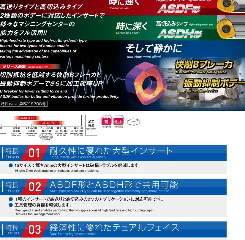
加工環境にあわせて選択可能な2種のボデーをラインアップ
・Lineup of two types of bodies so you can select the appropriate one for your working environment.
ボデーの使い分けマップ
Body usage map
シリーズ追加
Additional itemsASDF
形
ASDH
形
時
に
速く
Sometimes fast!時
に
深く
Sometimes deep!そして静かに
and Now more silent
High-feed-rate type
高送り
タイプ
High-cutting-depth type高切込み
タイプ
快削Bブレーカ
振動抑制ボデー
特許
Pat. No.第5218708号
高送りタイプと高切込みタイプ
2種類のボデーに対応したインサートで
様々なマシニングセンターの
能力をフル活用!
!
切削抵抗を低減する快削Bブレーカと
振動抑制ボデーでさらに加工能率UP
High-feed-rate type and high-cutting-depth type
Inserts for two types of bodies enable
taking full advantage of the capabilities of
various machining centers.
B breaker for lower cutting force and
ASDF bodies for better anti-vibration provide further productivity.
●
16サイズで厚さ7mmの大型インサートは破損トラブルを軽減します。
・16-size 7mm-thick large insert reduces breakage problems.
特長
Features
01
耐久性に優れた大型インサート
Large inserts with excellent durability
●
1種のインサートで高送りと高切込みの2つのアプリケーションに対応可能です。
●
工具管理の負担を軽減します。
・One type of insert enables performing the two applications of high feed rate and high cutting depth. ・Reduces tool management work.
特長
Features
02
ASDF形とASDH形で共用可能
ASDF type and ASDH type can be used together commonly applicable both to.
●
表裏で計8コーナの使用が可能です。
・Top and bottom can be used for a total of 8 corners.
特長
Features
03
経済性に優れたデュアルフェイス
Dual-face is highly economical.
10
8
6
4
2
0
0
0.5
1
1.5
2
2.5
一刃当りの送り量
fz
(mm/t) Feed rate軸方向切込み量
ap axial-depth of cut (mm)● Work materials with large variations in cutting depth such as cast surfaces, etc.
● Compatible with work environments where table feed rate is limited.
● If priority is on machined surface grade.
ASDH
形
ASDH type
大きな切込み量で加工能率を改善する高切込みタイプ
●鋳肌などの切込変動が大きい被削材
●テーブル送りが制限された環境
●加工面品位を優先する場合
High-cutting-depth type for improved cutting efficiency by cutting large amounts
High-feed-rate type with large cutting amount per flute improves cutting efficiency.
● Compatible with high-efficiency roughing that takes full advantage of machine capabilities.
● When priority is on durability for crushing cutting chips and interrupted cutting
ASDF
形
ASDF type
大きな1刃送り量で加工能率を改善する高送りタイプ ●機械の最大能力を引き出す高能率荒加工 ●切りくずの噛み込み、断続切削に対する耐久性を優先する場合
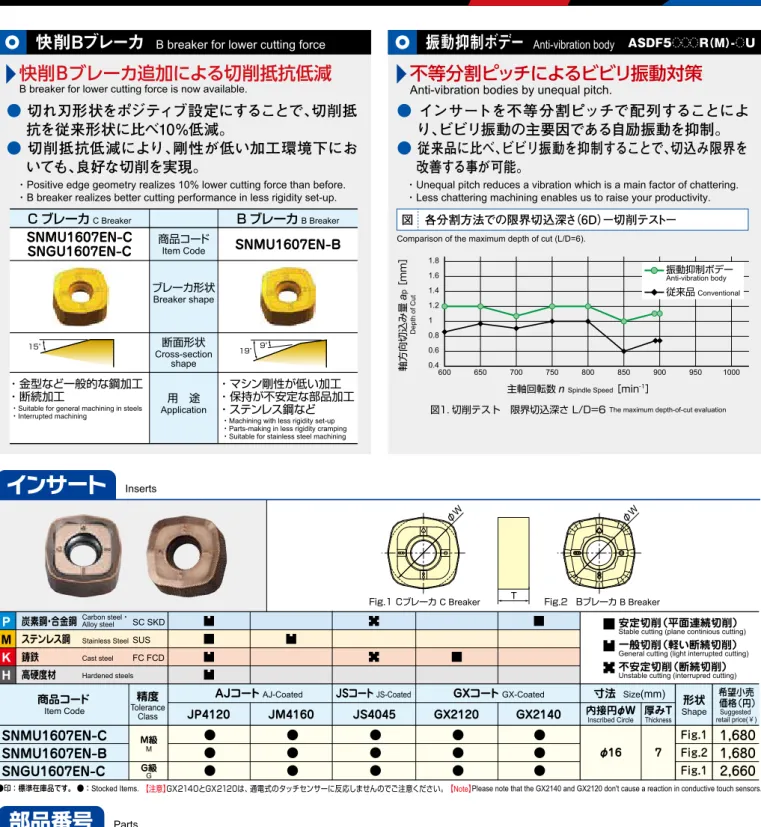
●
切れ刃形状をポジティブ設定にすることで、切削抵
抗を従来形状に比べ10%低減。
●
切削抵抗低減により、剛性が低い加工環境下にお
いても、良好な切削を実現。
・Positive edge geometry realizes 10% lower cutting force than before. ・B breaker realizes better cutting performance in less rigidity set-up.
快削Bブレーカ
B breaker for lower cutting force
快削Bブレーカ追加による切削抵抗低減
B breaker for lower cutting force is now available.C ブレーカ
C BreakerSNMU1607EN-C
SNGU1607EN-C
商品コードItem CodeSNMU1607EN-B
ブレーカ形状 Breaker shape 断面形状 Cross-section shape 用 途 ApplicationB ブレーカ
B Breaker・金型など一般的な鋼加工
・断続加工
・マシン剛性が低い加工
・保持が不安定な部品加工
・ステンレス鋼など
・Machining with less rigidity set-up ・Parts-making in less rigidity cramping ・Suitable for stainless steel machining ・Suitable for general machining in steels
・Interrupted machining
15° 19°9°
図 各分割方法での限界切込深さ
(6D)ー切削テストー
Comparison of the maximum depth of cut (L/D=6).
振動抑制ボデー
Anti-vibration body
●
インサートを不等分割ピッチで配列することによ
り、ビビリ振動の主要因である自励振動を抑制。
●
従来品に比べ、ビビリ振動を抑制することで、切込み限界を
改善する事が可能。
・Unequal pitch reduces a vibration which is a main factor of chattering. ・Less chattering machining enables us to raise your productivity.
ASDF5
R(M)- U
不等分割ピッチによるビビリ振動対策
Anti-vibration bodies by unequal pitch.
図1. 切削テスト 限界切込深さ L/D=6 The maximum depth-of-cut evaluation
軸方向切込み量
a
p [mm] Depth of Cut 1.8 1.6 1.4 1.2 1 0.8 0.6 0.4 600 650 700 750 800 850 900 950 1000 振動抑制ボデー Anti-vibration body 従来品Conventional主軸回転数
n
Spindle Speed [min-1]P
M
K
H
炭素鋼・合金鋼 ステンレス鋼 鋳鉄 高硬度材 SC SKD SUS FC FCD Carbon steel・ Alloy steel Stainless Steel Cast steel Hardened steelsSNMU1607EN-C
SNMU1607EN-B
SNGU1607EN-C
M級 M G級 G Fig.1 Fig.2 Fig.1●
●
●
●
●
●
●
●
●
●
●
●
●
●
●
商品コード
Item Code Shape
形状
寸法
Size(mm)JS4045
φ16 内接円φW Inscribed Circle 7 厚みT Thickness精度
Tolerance ClassAJコート
AJ-CoatedJSコート
JS-CoatedGX2120
GXコート
GX-Coated安定切削(平面連続切削) Stable cutting (plane continious cutting) 一般切削(軽い断続切削) General cutting (light interrupted cutting) 不安定切削(断続切削) Unstable cutting (interrupred cutting)
Fig.1 Cブレーカ C Breaker T Fig.2 Bブレーカ B Breaker
GX2140
希望小売 価格(円) Suggested retail price(¥)JP4120
JM4160
●印:標準在庫品です。 ●:Stocked Items.1,680
1,680
2,660
φW φW555-141
形状 Shape 適用カッタ Cutter body 部品名Parts クランプねじClamp screw
φ160未満 Less than φ160 φ160以上More than φ160
105-T20
105-T20L
550
4.9
1,720
1,720
P-37
レンチ Wrench ねじ焼き付き防止剤 Screw anti-seizure agent
本体には付属しておりません(別売) Not included with product (sold separately)
環境負荷低減への配慮により、レンチ、ねじ焼き付き防止剤、アーバ用ネジは別売りとさせて頂きました。ご理解・ご協力をお願い致します。 To reduce environmental loads, wrenches, screw anti-seizure agent, and arbor screws are sold separately. We ask for your understanding and cooperation.
ASDF5 R(M)-
ASDH5 R(M)-希望小売 価格(円) Suggested retail price (¥) 希望小売 価格(円) Suggested retail price (¥) 希望小売 価格(円) Suggested retail price (¥)820
希望小売 価格(円) Suggested retail price (¥) 締付トルク Fastening torque (N・m) ①インサート取付け部に切りくず等の異物が付着していないように清掃して下さい。 ②クランプねじのネジ部に焼き付き防止剤を塗布し、インサートを拘束面方向に押当てながら適切なトルクで締付けて下さい。(推奨締付けトルク4.9Nm) ③締付け後にインサートと座面及び拘束面に隙間が無いことを確認して下さい。 ④インサートのコーナ交換は反時計方向に回転させる順番で行って下さい。① Clean the place where the insert will be attached so that there are no foreign materials such as cutting chip stuck on.
② Apply anti-seizure agent to the thread portion of the clamp screw, and while pressing the insert against the restraint surface, tighten the screw to the appropriate torque. (Recommended tightening torque: 4.9Nm)
③ After tightening, check that there are no gaps between the insert and the base or the restraint surface. ④ Change the insert corner by turning the insert in a counterclockwise direction.
④コーナ交換の回転方向
Corner change rotation directionコーナ識別記号(△:表 無:裏)
②拘束面方向
Restraint surface direction Corner identification marks: △: Top; No mark: Bottom
ラインナップ
Line Up
Insertsインサート
Parts部品番号
【注意】GX2140とGX2120は、通電式のタッチセンサーに反応しませんのでご注意ください。【Note】Please note that the GX2140 and GX2120 don't cause a reaction in conductive touch sensors.
インサートの交換手順
Insert replacement procedure
銅 炭素鋼 合金鋼 ステンレス鋼工具鋼 プリハードン鋼焼入れ鋼 30~45HRC 焼入れ鋼 45~55HRC 55~62HRC焼入れ鋼Copper Carbon steel
Alloy steel Stainless steelTool steel Pre-hardened steel Hardened steel 30̃45HRC Hardened steel 45̃55HRC Hardened steel55̃62HRC Applications 加工 用途 Roughing
荒
Finishing仕上
JP4120 JM4160●
加工環境にあわせて選択可能な2種のボデーをラインアップ
・Lineup of two types of bodies so you can select the appropriate one for your working environment.
ボデーの使い分けマップ
Body usage map
シリーズ追加
Additional itemsASDF
形
ASDH
形
時
に
速く
Sometimes fast!時
に
深く
Sometimes deep!そして静かに
and Now more silent
High-feed-rate type
高送り
タイプ
High-cutting-depth type高切込み
タイプ
快削Bブレーカ
振動抑制ボデー
特許
Pat. No.第5218708号
高送りタイプと高切込みタイプ
2種類のボデーに対応したインサートで
様々なマシニングセンターの
能力をフル活用!
!
切削抵抗を低減する快削Bブレーカと
振動抑制ボデーでさらに加工能率UP
High-feed-rate type and high-cutting-depth type
Inserts for two types of bodies enable
taking full advantage of the capabilities of
various machining centers.
B breaker for lower cutting force and
ASDF bodies for better anti-vibration provide further productivity.
●
16サイズで厚さ7mmの大型インサートは破損トラブルを軽減します。
・16-size 7mm-thick large insert reduces breakage problems.
特長
Features
01
耐久性に優れた大型インサート
Large inserts with excellent durability
●
1種のインサートで高送りと高切込みの2つのアプリケーションに対応可能です。
●
工具管理の負担を軽減します。
・One type of insert enables performing the two applications of high feed rate and high cutting depth. ・Reduces tool management work.
特長
Features
02
ASDF形とASDH形で共用可能
ASDF type and ASDH type can be used together commonly applicable both to.
●
表裏で計8コーナの使用が可能です。
・Top and bottom can be used for a total of 8 corners.
特長
Features
03
経済性に優れたデュアルフェイス
Dual-face is highly economical.
10
8
6
4
2
0
0
0.5
1
1.5
2
2.5
一刃当りの送り量
fz
(mm/t) Feed rate軸方向切込み量
ap axial-depth of cut (mm)● Work materials with large variations in cutting depth such as cast surfaces, etc.
● Compatible with work environments where table feed rate is limited.
● If priority is on machined surface grade.
ASDH
形
ASDH type
大きな切込み量で加工能率を改善する高切込みタイプ
●鋳肌などの切込変動が大きい被削材
●テーブル送りが制限された環境
●加工面品位を優先する場合
High-cutting-depth type for improved cutting efficiency by cutting large amounts
High-feed-rate type with large cutting amount per flute improves cutting efficiency.
● Compatible with high-efficiency roughing that takes full advantage of machine capabilities.
● When priority is on durability for crushing cutting chips and interrupted cutting
ASDF
形
ASDF type
大きな1刃送り量で加工能率を改善する高送りタイプ ●機械の最大能力を引き出す高能率荒加工 ●切りくずの噛み込み、断続切削に対する耐久性を優先する場合
●
切れ刃形状をポジティブ設定にすることで、切削抵
抗を従来形状に比べ10%低減。
●
切削抵抗低減により、剛性が低い加工環境下にお
いても、良好な切削を実現。
・Positive edge geometry realizes 10% lower cutting force than before. ・B breaker realizes better cutting performance in less rigidity set-up.
快削Bブレーカ
B breaker for lower cutting force
快削Bブレーカ追加による切削抵抗低減
B breaker for lower cutting force is now available.C ブレーカ
C BreakerSNMU1607EN-C
SNGU1607EN-C
商品コードItem CodeSNMU1607EN-B
ブレーカ形状 Breaker shape 断面形状 Cross-section shape 用 途 ApplicationB ブレーカ
B Breaker・金型など一般的な鋼加工
・断続加工
・マシン剛性が低い加工
・保持が不安定な部品加工
・ステンレス鋼など
・Machining with less rigidity set-up ・Parts-making in less rigidity cramping ・Suitable for stainless steel machining ・Suitable for general machining in steels
・Interrupted machining
15° 19°9°
図 各分割方法での限界切込深さ
(6D)ー切削テストー
Comparison of the maximum depth of cut (L/D=6).
振動抑制ボデー
Anti-vibration body
●
インサートを不等分割ピッチで配列することによ
り、ビビリ振動の主要因である自励振動を抑制。
●
従来品に比べ、ビビリ振動を抑制することで、切込み限界を
改善する事が可能。
・Unequal pitch reduces a vibration which is a main factor of chattering. ・Less chattering machining enables us to raise your productivity.
ASDF5
R(M)- U
不等分割ピッチによるビビリ振動対策
Anti-vibration bodies by unequal pitch.
図1. 切削テスト 限界切込深さ L/D=6 The maximum depth-of-cut evaluation
軸方向切込み量
a
p [mm] Depth of Cut 1.8 1.6 1.4 1.2 1 0.8 0.6 0.4 600 650 700 750 800 850 900 950 1000 振動抑制ボデー Anti-vibration body 従来品Conventional主軸回転数
n
Spindle Speed [min-1]P
M
K
H
炭素鋼・合金鋼 ステンレス鋼 鋳鉄 高硬度材 SC SKD SUS FC FCD Carbon steel・ Alloy steel Stainless Steel Cast steel Hardened steelsSNMU1607EN-C
SNMU1607EN-B
SNGU1607EN-C
M級 M G級 G Fig.1 Fig.2 Fig.1●
●
●
●
●
●
●
●
●
●
●
●
●
●
●
商品コード
Item Code Shape
形状
寸法
Size(mm)JS4045
φ16 内接円φW Inscribed Circle 7 厚みT Thickness精度
Tolerance ClassAJコート
AJ-CoatedJSコート
JS-CoatedGX2120
GXコート
GX-Coated安定切削(平面連続切削) Stable cutting (plane continious cutting) 一般切削(軽い断続切削) General cutting (light interrupted cutting) 不安定切削(断続切削) Unstable cutting (interrupred cutting)
Fig.1 Cブレーカ C Breaker T Fig.2 Bブレーカ B Breaker
GX2140
希望小売 価格(円) Suggested retail price(¥)JP4120
JM4160
●印:標準在庫品です。 ●:Stocked Items.1,680
1,680
2,660
φW φW555-141
形状 Shape 適用カッタ Cutter body 部品名Parts クランプねじClamp screw
φ160未満 Less than φ160 φ160以上More than φ160
105-T20
105-T20L
550
4.9
1,720
1,720
P-37
レンチ Wrench ねじ焼き付き防止剤 Screw anti-seizure agent
本体には付属しておりません(別売) Not included with product (sold separately)
環境負荷低減への配慮により、レンチ、ねじ焼き付き防止剤、アーバ用ネジは別売りとさせて頂きました。ご理解・ご協力をお願い致します。 To reduce environmental loads, wrenches, screw anti-seizure agent, and arbor screws are sold separately. We ask for your understanding and cooperation.
ASDF5 R(M)-
ASDH5 R(M)-希望小売 価格(円) Suggested retail price (¥) 希望小売 価格(円) Suggested retail price (¥) 希望小売 価格(円) Suggested retail price (¥)820
希望小売 価格(円) Suggested retail price (¥) 締付トルク Fastening torque (N・m) ①インサート取付け部に切りくず等の異物が付着していないように清掃して下さい。 ②クランプねじのネジ部に焼き付き防止剤を塗布し、インサートを拘束面方向に押当てながら適切なトルクで締付けて下さい。(推奨締付けトルク4.9Nm) ③締付け後にインサートと座面及び拘束面に隙間が無いことを確認して下さい。 ④インサートのコーナ交換は反時計方向に回転させる順番で行って下さい。① Clean the place where the insert will be attached so that there are no foreign materials such as cutting chip stuck on.
② Apply anti-seizure agent to the thread portion of the clamp screw, and while pressing the insert against the restraint surface, tighten the screw to the appropriate torque. (Recommended tightening torque: 4.9Nm)
③ After tightening, check that there are no gaps between the insert and the base or the restraint surface. ④ Change the insert corner by turning the insert in a counterclockwise direction.
④コーナ交換の回転方向
Corner change rotation directionコーナ識別記号(△:表 無:裏)
②拘束面方向
Restraint surface direction Corner identification marks: △: Top; No mark: Bottom
ラインナップ
Line Up
Insertsインサート
Parts部品番号
【注意】GX2140とGX2120は、通電式のタッチセンサーに反応しませんのでご注意ください。【Note】Please note that the GX2140 and GX2120 don't cause a reaction in conductive touch sensors.
ラインナップ
Line Up
ラインナップ
Line Up
Y-100
ラインナップ
Line Up
アーバ用ねじは付属しません。【注意】 【Note】Arbor screw is not included.
ASDF
形
ASDF
形
ASDF
type
【高送りタイプ】
【High-feed-rate type】
標準切削条件表
Recommended Cutting Conditions
Fig.1(クーラント穴有)(With coolant hole) Fig.2(クーラント穴無)(Without coolant hole) Fig.3(クーラント穴無)(Without coolant hole)
a b φDc1 φDc2 Lf φd φd1 R ap φDb φ20 φ14 φ66.7 ap a b φDc1 φDc2 Lf φd φd1 R φDb ap b φDc1 φDc2 φd1 Lf R a φd φDb
は数字が入ります。 Numeric figure in a circle .
ASDF5
(M)-(U)
R
※ASDF形は「工具最外径ΦDc2」を刃径基準としています。ASDH形とは異なるので注意してください。
※ASDF type uses the maximum tool diameter ∅Dc2 as the flute diameter standard. This is different than for ASDH type, so care should be taken. ●印:標準在庫品です。●:Stocked Items.
参考切削条件
Reference cutting condition ASDF形(高送り)v
c = 180m/min fz = 1.5mm/tap
×ae
= 1.0 × 0.7Dmm エアブロー 工具径φDc2(mm) Tool dia. 切 り く ず 排出量 Q(cm 3/min )Metal removal rate
切削動力 Pc( kw ) Cutting power 1000 900 800 700 600 500 400 300 200 100 0 25 20 15 10 5 0 0 63-4NT 80-4NT 100-5NT 125-6NT 160-8NT 参考切削条件における各工具径ごとの必要切削動力
Pc
の算出結果です。工具径選 定の目安としてご使用ください。 本数値は一般的な機械条件で算出している為、実際の数値と異なる場合があります。 The chart shows the calculated results for required cutting power Pc for each tool diameter under the reference cutting conditions. Please use as criteria when selecting tool diameter. These values are calculated from general machinery conditions, and may be different from actual values.ASDF type (High-feed-rate type) Air-blow
Pc[鋳鉄 FC250] Cast Iron Pc[炭素鋼 S50C] Carbon Steel
Q
プログラム上の刃先形状定義は下記を参照ください。 Refer to the following for the flute tip condition definitions for programming.
※傾斜加工はφ63,φ80で0.5°以下。φ100以上では行わないで下さい。
※工具突出しが長い場合(
L
/φDc2≧ 3)はap
を調整して下さい。削り残し量Remains
1.33mm
近似
R
定義Approximate R definition=
R
6
削り残し量Remains
1.33mm
ASDF
形を形状加工で使用する場合
When using ASDF type for shaping cutting※For slanted cutting using ∅63 or ∅80, perform at 0.5° or less. Do not perform using ∅100 or larger.
※When tool protrusion length is long (L/φDc2 ≧ 3), adjust ap.
R
6
【注意】 【Note】 ①GX2140とGX2120は、通電式のタッチセンサーに反応しませんのでご注意ください。 ②被削材、加工形状に合わせて、適切なクーラントを使用してください。 ③この切削条件表は切削条件の目安を示すものです。実際の加工では、加工形状、目的、使用機械等により条件を調整してください。 ④インサートの交換は早めに行い、過度の使用による破損を防止してください。 ⑤排出した切りくずは、飛散し作業者を切傷させ、やけどあるいは目に入って負傷させる恐れがありますので、ご使用に際してはその周囲に安全カバー を取付け、保護メガネなどの保護具を着用し、安全な環境で作業されることをお願い致します。 ⑥不水溶性切削油は、火災の恐れがありますので使用しないでください。①Please note that the GX2140 and GX2120 don't cause a reaction in conductive touch sensors. ②Use the appropriate coolant for the work material and machining shape.
③These conditions are for general guidance; in actual machining conditions adjust the parameters according to your actual machine and work-piece conditions. ④In order to avoid of insert breakage, please change insert earlier.
⑤The steel chips may cause cuts, burns or damages to eyes. Be sure to install the safty cover around the tool and wear the safty glasses when carring out any works. ⑥Please don't use cutting oil as coolant.(It may be cause of fire.)
φ63-4枚刃
4 flutes 回転数 n(min-1) 送り速度v
f(mm/min)φ80-4枚刃
4 flutes 回転数 n(min-1) 送り速度v
f(mm/min)φ100-5枚刃
5 flutes 回転数 n(min-1) 送り速度v
f(mm/min)φ125-6枚刃
6 flutes 回転数 n(min-1) 送り速度v
f(mm/min)φ160-8枚刃
8 flutes 回転数 n(min-1) 送り速度v
f(mm/min)810
710
610
460
460
810
350
4850
4240
3640
1460
1820
4850
570
640
560
480
360
360
640
280
3820
3340
2870
1150
1430
3820
450
510
450
380
290
290
510
220
3820
3340
2870
1150
1430
3820
450
410
360
310
230
230
410
180
3670
3210
2750
1100
1380
3670
430
320
280
240
180
180
320
140
3820
3340
2870
1150
1430
3820
450
150~200
100~180
100~160
80~120
80~100
100~180
60~100
1.0~2.0
1.0~2.0
1.0~2.0
0.4~0.8
0.8~1.2
1.0~2.0
0.3~0.6
被削材
Work material 一般構造用鋼 Mild Steels (200HB以下) 炭素鋼・合金鋼Carbon & Alloy Steels (30HRC以下)
炭素鋼・合金鋼
Carbon & Alloy Steels (30~40HRC)
炭素鋼・合金鋼
Carbon & Alloy Steels (40~45HRC) ステンレス鋼 Stainless Steels SUS
鋳 鉄
Cast Iron FC, FCD 焼入れ鋼 Hardened Steels (45~50HRC)推奨材種
Recommended grade 一刃当りの 送り fz(mm/t) Feed rate 切削速度v
c(m/min) Cutting Speed※
GX2140
JS4045
GX2140
JS4045
JP4120
JS4045
GX2140
GX2120
JP4120
JS4045
JP4120
JS4045
JP4120
JM4160
JP4120
v
c=160m/min f
z=1.5mm/t ap=1.5mm ae=0.7×φDc
v
c=140m/min f
z=1.5mm/t ap=1.5mm ae=0.7×φDc
v
c=120m/min f
z=1.5mm/t ap=1.5mm ae=0.7×φDc
v
c=90m/min f
z=0.8mm/t ap=1.0mm ae=0.7×φDc
v
c=90m/min f
z=1mm/t ap=1.0mm ae=0.7×φDc
v
c=160m/min f
z=1.5mm/t ap=1.5mm ae=0.7×φDc
v
c=70m/min f
z=0.4mm/t ap=0.8mm ae=0.7×φDc
a
ea
p【高送りタイプ】
High-feed-rate type
ASDF
type ※赤字は第一推奨材種です。 Red indicates primary recommended grade.切削性能
Cutting performance
※図、表等のデータは試験結果の一例です。 ※Drawings, data in tables, etc. are examples of test results. 切削時間 Cutting time (min)
逃げ面摩耗幅 V B max Flank wear (mm) 0 0.1 0.2 0.3 0.4 0.5 0.6 0 20 40 60 80 100 120 140 160 切削条件 Cutting Conditions 工具 Tool:ASDF5063R-4 vc = 184m/min fz = 1.5mm/t ap×ae= 1 × 40mm エアブローAir-blow 切削条件 Cutting Conditions 工具 Tool:ASDF5063R-4 vc = 100m/min fz = 1.0mm/t ap×ae= 1 × 40mm エアブローAir-blow 切削条件 Cutting Conditions 工具 Tool:ASDF5063R-4 vc = 90m/min fz = 0.8mm/t ap×ae= 1 × 40mm エアブローAir-blow 150min後
従来品
Conventional切削時間 Cutting time (min)
逃げ面摩耗幅 V B max Flank wear (mm) 0 0.1 0.2 0.3 0.4 0.5 0.6 0 20 40 60 80 100 120 140 160 48min後
ASDF
切削時間 Cutting time (min)
逃げ面摩耗幅 V B max Flank wear (mm) 0 0.1 0.2 0.3 0.4 0.5 0.6 0 20 40 60 80 100 120 140 160 70min後
ASDF
従来品
ConventionalASDF
炭素鋼 S50C
Carbon Steel
01
02
プリハードン鋼
(42HRC)
Pre-Harden
Steel
03
ステンレス鋼
(SUS304)
Stainless
Steel
Tool diameter and cutting power工具径と切削動力
タイプ
Type 商品コードItem code
在庫 Stock 刃数 No.of Flutes 寸 法Size (mm) 適用 インサート Inserts 希望小売 価格(円) Suggested Retail Price (¥) 工具径 Cutting dia.
φDb
全長 Overall lengthLf
ℓ
キー幅 Key width インロー Inlayφd
φd
1ap
ワイパー Wiper 形状Figure 重量 Weight (kg)φDc
1φDc
2a
b
Recommended推奨max
ASDF5063R-4
●
4
42
63
60 50
19
8.4
5 22.225 17
≦ 2
3 1.3 Fig.1 0.7
SNMU1607EN-C
SNGU1607EN-C
SNMU1607EN-B
66,200
ASDF5063R-4U
●
4
42
63
60 50
19
8.4
5 22.225 17
≦ 2
3 1.3 Fig.1 0.7
66,200
ASDF5080R-4
●
4
59
80
76 63
32 12.7
8 31.75
26
≦ 2
3 1.3 Fig.1 1.3
72,500
ASDF5080R-4U
●
4
59
80
76 63
32 12.7
8 31.75
26
≦ 2
3 1.3 Fig.1 1.3
72,500
ASDF5100R-5
●
5
79 100
96 63
32 12.7
8 31.75
26
≦ 2
3 1.3 Fig.1 2.4
89,400
ASDF5100R-5U
●
5
79 100
96 63
32 12.7
8 31.75
26
≦ 2
3 1.3 Fig.1 2.4
89,400
ASDF5125R-6
●
6 104 125 100 63
38 15.9 10 38.1
60
≦ 2
3 1.3 Fig.2 3.0
111,000
ASDF5125R-6U
●
6 104 125 100 63
38 15.9 10 38.1
60
≦ 2
3 1.3 Fig.2 3.0
111,000
ASDF5125R-8U
●
8 104 125 100 63
38 15.9 10 38.1
60
≦ 2
3 1.3 Fig.2 3.0
127,000
ASDF5160R-8
●
8 139 160 105 63
38 19.1 11 50.8
80
≦ 2
3 1.3 Fig.2 4.3
147,000
ASDF5160R-8U
●
8 139 160 105 63
38 19.1 11 50.8
80
≦ 2
3 1.3 Fig.2 4.3
147,000
ASDF5160R-10U
●
10 139 160 105 63
38 19.1 11 50.8
80
≦ 2
3 1.3 Fig.2 4.3
165,000
ASDF5063RM-4
●
4
42
63
60 50
20 10.4 6.3 22
17
≦ 2
3 1.3 Fig.1 0.7
66,200
ASDF5063RM-4U
●
4
42
63
60 50
20 10.4 6.3 22
17
≦ 2
3 1.3 Fig.1 0.7
66,200
ASDF5080RM-4
●
4
59
80
76 63
22 12.4
7 27
20
≦ 2
3 1.3 Fig.1 1.5
72,500
ASDF5080RM-4U
●
4
59
80
76 63
22 12.4
7 27
20
≦ 2
3 1.3 Fig.1 1.5
72,500
ASDF5100RM-5
●
5
79 100
96 63
32 14.4
8 32
26
≦ 2
3 1.3 Fig.1 2.4
89,400
ASDF5100RM-5U
●
5
79 100
96 63
32 14.4
8 32
26
≦ 2
3 1.3 Fig.1 2.4
89,400
ASDF5125RM-6
●
6 104 125 100 63
30 16.4
9 40
56
≦ 2
3 1.3 Fig.2 3.0
111,000
ASDF5125RM-6U
●
6 104 125 100 63
30 16.4
9 40
56
≦ 2
3 1.3 Fig.2 3.0
111,000
ASDF5125RM-8U
●
8 104 125 100 63
30 16.4
9 40
56
≦ 2
3 1.3 Fig.2 3.0
127,000
ASDF5160RM-8
●
8 139 160 105 63
30 16.4
9 40
68
≦ 2
3 1.3 Fig.3 4.3
147,000
ASDF5160RM-8U
●
8 139 160 105 63
30 16.4
9 40
68
≦ 2
3 1.3 Fig.3 4.3
147,000
ASDF5160RM-10U ●
10 139 160 105 63
30 16.4
9 40
68
≦ 2
3 1.3 Fig.3 4.3
165,000
ボアタイプ Bore type 内径ミリサイズInternal diameter mm size
内径インチサイズ
Internal diameter inch size
ラインナップ
Line Up
ラインナップ
Line Up
Y-100
ラインナップ
Line Up
アーバ用ねじは付属しません。【注意】 【Note】Arbor screw is not included.
ASDF
形
ASDF
形
ASDF
type
【高送りタイプ】
【High-feed-rate type】
標準切削条件表
Recommended Cutting Conditions
Fig.1(クーラント穴有)(With coolant hole) Fig.2(クーラント穴無)(Without coolant hole) Fig.3(クーラント穴無)(Without coolant hole)
a b φDc1 φDc2 Lf φd φd1 R ap φDb φ20 φ14 φ66.7 ap a b φDc1 φDc2 Lf φd φd1 R φDb ap b φDc1 φDc2 φd1 Lf R a φd φDb
は数字が入ります。 Numeric figure in a circle .
ASDF5
(M)-(U)
R
※ASDF形は「工具最外径ΦDc2」を刃径基準としています。ASDH形とは異なるので注意してください。
※ASDF type uses the maximum tool diameter ∅Dc2 as the flute diameter standard. This is different than for ASDH type, so care should be taken. ●印:標準在庫品です。●:Stocked Items.
参考切削条件
Reference cutting condition ASDF形(高送り)v
c = 180m/min fz = 1.5mm/tap
×ae
= 1.0 × 0.7Dmm エアブロー 工具径φDc2(mm) Tool dia. 切 り く ず 排出量 Q(cm 3/min )Metal removal rate
切削動力 Pc( kw ) Cutting power 1000 900 800 700 600 500 400 300 200 100 0 25 20 15 10 5 0 0 63-4NT 80-4NT 100-5NT 125-6NT 160-8NT 参考切削条件における各工具径ごとの必要切削動力
Pc
の算出結果です。工具径選 定の目安としてご使用ください。 本数値は一般的な機械条件で算出している為、実際の数値と異なる場合があります。 The chart shows the calculated results for required cutting power Pc for each tool diameter under the reference cutting conditions. Please use as criteria when selecting tool diameter. These values are calculated from general machinery conditions, and may be different from actual values.ASDF type (High-feed-rate type) Air-blow
Pc[鋳鉄 FC250] Cast Iron Pc[炭素鋼 S50C] Carbon Steel
Q
プログラム上の刃先形状定義は下記を参照ください。 Refer to the following for the flute tip condition definitions for programming.
※傾斜加工はφ63,φ80で0.5°以下。φ100以上では行わないで下さい。
※工具突出しが長い場合(
L
/φDc2≧ 3)はap
を調整して下さい。削り残し量Remains
1.33mm
近似
R
定義Approximate R definition=
R
6
削り残し量Remains
1.33mm
ASDF
形を形状加工で使用する場合
When using ASDF type for shaping cutting※For slanted cutting using ∅63 or ∅80, perform at 0.5° or less. Do not perform using ∅100 or larger.
※When tool protrusion length is long (L/φDc2 ≧ 3), adjust ap.
R
6
【注意】 【Note】 ①GX2140とGX2120は、通電式のタッチセンサーに反応しませんのでご注意ください。 ②被削材、加工形状に合わせて、適切なクーラントを使用してください。 ③この切削条件表は切削条件の目安を示すものです。実際の加工では、加工形状、目的、使用機械等により条件を調整してください。 ④インサートの交換は早めに行い、過度の使用による破損を防止してください。 ⑤排出した切りくずは、飛散し作業者を切傷させ、やけどあるいは目に入って負傷させる恐れがありますので、ご使用に際してはその周囲に安全カバー を取付け、保護メガネなどの保護具を着用し、安全な環境で作業されることをお願い致します。 ⑥不水溶性切削油は、火災の恐れがありますので使用しないでください。①Please note that the GX2140 and GX2120 don't cause a reaction in conductive touch sensors. ②Use the appropriate coolant for the work material and machining shape.
③These conditions are for general guidance; in actual machining conditions adjust the parameters according to your actual machine and work-piece conditions. ④In order to avoid of insert breakage, please change insert earlier.
⑤The steel chips may cause cuts, burns or damages to eyes. Be sure to install the safty cover around the tool and wear the safty glasses when carring out any works. ⑥Please don't use cutting oil as coolant.(It may be cause of fire.)
φ63-4枚刃
4 flutes 回転数 n(min-1) 送り速度v
f(mm/min)φ80-4枚刃
4 flutes 回転数 n(min-1) 送り速度v
f(mm/min)φ100-5枚刃
5 flutes 回転数 n(min-1) 送り速度v
f(mm/min)φ125-6枚刃
6 flutes 回転数 n(min-1) 送り速度v
f(mm/min)φ160-8枚刃
8 flutes 回転数 n(min-1) 送り速度v
f(mm/min)810
710
610
460
460
810
350
4850
4240
3640
1460
1820
4850
570
640
560
480
360
360
640
280
3820
3340
2870
1150
1430
3820
450
510
450
380
290
290
510
220
3820
3340
2870
1150
1430
3820
450
410
360
310
230
230
410
180
3670
3210
2750
1100
1380
3670
430
320
280
240
180
180
320
140
3820
3340
2870
1150
1430
3820
450
150~200
100~180
100~160
80~120
80~100
100~180
60~100
1.0~2.0
1.0~2.0
1.0~2.0
0.4~0.8
0.8~1.2
1.0~2.0
0.3~0.6
被削材
Work material 一般構造用鋼 Mild Steels (200HB以下) 炭素鋼・合金鋼Carbon & Alloy Steels (30HRC以下)
炭素鋼・合金鋼
Carbon & Alloy Steels (30~40HRC)
炭素鋼・合金鋼
Carbon & Alloy Steels (40~45HRC) ステンレス鋼 Stainless Steels SUS
鋳 鉄
Cast Iron FC, FCD 焼入れ鋼 Hardened Steels (45~50HRC)推奨材種
Recommended grade 一刃当りの 送り fz(mm/t) Feed rate 切削速度v
c(m/min) Cutting Speed※
GX2140
JS4045
GX2140
JS4045
JP4120
JS4045
GX2140
GX2120
JP4120
JS4045
JP4120
JS4045
JP4120
JM4160
JP4120
v
c=160m/min f
z=1.5mm/t ap=1.5mm ae=0.7×φDc
v
c=140m/min f
z=1.5mm/t ap=1.5mm ae=0.7×φDc
v
c=120m/min f
z=1.5mm/t ap=1.5mm ae=0.7×φDc
v
c=90m/min f
z=0.8mm/t ap=1.0mm ae=0.7×φDc
v
c=90m/min f
z=1mm/t ap=1.0mm ae=0.7×φDc
v
c=160m/min f
z=1.5mm/t ap=1.5mm ae=0.7×φDc
v
c=70m/min f
z=0.4mm/t ap=0.8mm ae=0.7×φDc
a
ea
p【高送りタイプ】
High-feed-rate type
ASDF
type ※赤字は第一推奨材種です。 Red indicates primary recommended grade.切削性能
Cutting performance
※図、表等のデータは試験結果の一例です。 ※Drawings, data in tables, etc. are examples of test results. 切削時間 Cutting time (min)
逃げ面摩耗幅 V B max Flank wear (mm) 0 0.1 0.2 0.3 0.4 0.5 0.6 0 20 40 60 80 100 120 140 160 切削条件 Cutting Conditions 工具 Tool:ASDF5063R-4 vc = 184m/min fz = 1.5mm/t ap×ae= 1 × 40mm エアブローAir-blow 切削条件 Cutting Conditions 工具 Tool:ASDF5063R-4 vc = 100m/min fz = 1.0mm/t ap×ae= 1 × 40mm エアブローAir-blow 切削条件 Cutting Conditions 工具 Tool:ASDF5063R-4 vc = 90m/min fz = 0.8mm/t ap×ae= 1 × 40mm エアブローAir-blow 150min後
従来品
Conventional切削時間 Cutting time (min)
逃げ面摩耗幅 V B max Flank wear (mm) 0 0.1 0.2 0.3 0.4 0.5 0.6 0 20 40 60 80 100 120 140 160 48min後
ASDF
切削時間 Cutting time (min)
逃げ面摩耗幅 V B max Flank wear (mm) 0 0.1 0.2 0.3 0.4 0.5 0.6 0 20 40 60 80 100 120 140 160 70min後
ASDF
従来品
ConventionalASDF
炭素鋼 S50C
Carbon Steel
01
02
プリハードン鋼
(42HRC)
Pre-Harden
Steel
03
ステンレス鋼
(SUS304)
Stainless
Steel
Tool diameter and cutting power工具径と切削動力
ラインナップ
Line Up
アーバ用ねじは付属しません。
【注意】 【Note】Arbor screw is not included.
ASDH
形
ASDH
形
ASDH
type
ASDH
type【高切込みタイプ】
【High-cutting-depth type】
標準切削条件表
Recommended Cutting Conditions
ASDH5
(M)-
R
a
ea
p【高切込みタイプ】
High-cutting-depth type
※赤字は第一推奨材種です。 Red indicates primary recommended grade.切削性能
Cutting performance
炭素鋼 S50C
Carbon Steel
01
は数字が入ります。 Numeric figure in a circle .
SNMU1607EN-C
SNGU1607EN-C
SNMU1607EN-B
Fig.1(クーラント穴有)(With coolant hole) Fig.2(クーラント穴無)(Without coolant hole) Fig.3(クーラント穴無)(Without coolant hole)
商品コード
Item Code
ボアタイプ
Bore type
内径インチサイズ
Internal diameter inch size
内径ミリサイズ
Internal diameter mm size
在庫
Stock
刃数
Cutting dia.工具径 キー幅Key width インローInlay
max Recommended推奨 Overall length全長 No.of Flutes
寸 法
Size(㎜)重量
Weight (kg)形状
Shapeワイパー
Wiperタイプ
Type適用インサート
InsertsASDH5063R-4
ASDH5080R-4
ASDH5100R-5
ASDH5125R-6
ASDH5125R-8
ASDH5160R-8
ASDH5160R-10
ASDH5063RM-4
ASDH5080RM-4
ASDH5100RM-5
ASDH5125RM-6
ASDH5125RM-8
ASDH5160RM-8
ASDH5160RM-10
66,200
72,500
89,400
111,000
129,000
147,000
165,000
66,200
72,500
89,400
111,000
129,000
147,000
165,000
●
●
●
●
●
●
●
●
●
●
●
●
●
●
4
4
5
6
8
8
10
4
4
5
6
8
8
10
63
80
100
125
125
160
160
63
80
100
125
125
160
160
75
92
112
137
137
172
172
75
92
112
137
137
172
172
50
63
63
63
63
63
63
50
63
63
63
63
63
63
22.225
31.75
31.75
38.1
38.1
50.8
50.8
22
27
32
40
40
40
40
17
26
26
60
60
80
80
17
20
26
56
56
68
68
Fig.1
Fig.1
Fig.1
Fig.2
Fig.2
Fig.2
Fig.2
Fig.1
Fig.1
Fig.1
Fig.2
Fig.2
Fig.3
Fig.3
≦5
≦5
≦5
≦5
≦5
≦5
≦5
≦5
≦5
≦5
≦5
≦5
≦5
≦5
10
10
10
10
10
10
10
10
10
10
10
10
10
10
19
32
32
38
38
38
38
20
22
32
30
30
30
30
8.4
12.7
12.7
15.9
15.9
19.1
19.1
10.4
12.4
14.4
16.4
16.4
16.4
16.4
5
8
8
10
10
11
11
6.3
7
8
9
9
9
9
60
76
96
100
100
105
105
60
76
96
100
100
105
105
0.9
1.7
2.8
3.6
3.6
5.2
5.1
0.9
1.8
2.8
3.6
3.5
5.2
5.1
1.3
1.3
1.3
1.3
1.3
1.3
1.3
1.3
1.3
1.3
1.3
1.3
1.3
1.3
ΦD
c
1ΦD
c
2ΦD
b
Lf
ℓ
a
b
Φd
Φd
1ap
※ASDH形は「工具先端径ΦD
c
1」を刃径基準としています。ASDF形とは異なるので注意してください。※ASDH type uses the tool tip diameter ∅Dc1 as the flute diameter standard. This is different than for ASDF type, so care should be taken.
※ASDH形は形状加工には使用できません。
※
ASDF type cannot be used for shaping cutting.
ap ap ap a b b b φDc1 φDc2 Lf φd φd1 φDc1 φDc2 φd1 φDc1 φDc2 φd1 R Lf R Lf R φDb a φd φDb a φd φDb ●印:標準在庫品です。●:Stocked Items.
希望小売
価格(円)
Suggested retail price (¥) 参考切削条件における各工具径ごとの必要切削動力Pc
の 算出結果です。工具径選定の目安としてご使用ください。 本数値は一般的な機械条件で算出している為、実際の数値 と異なる場合があります。The chart shows the calculated results for required cutting power Pc for each tool diameter under the reference cutting conditions. Please use as criteria when selecting tool diameter.
These values are calculated from general machinery conditions, and may be different from actual values.
参考切削条件
Reference cutting condition ASDH形(高切込み)v
c = 150m/min fz = 0.3mm/tap
×ae
= 5.0 × 0.7Dmm エアブローASDH type (High-cutting-depth type) Air-blow 工具径φDc1(mm) Tool dia. 切 り く ず 排出量 Q(cm 3/min )
Metal removal rate
切削動力 Pc ( kw ) Cutting power 1000 900 800 700 600 500 400 300 200 100 0 25 20 15 10 5 0 0 63-4NT 80-4NT 100-5NT 125-6NT 125-8NT 160-8NT 160-10NT Pc[鋳鉄 FC250] Cast Iron Pc[炭素鋼 S50C] Carbon Steel Q φ20 φ14 φ 66.7 【注意】 【Note】 ①GX2140とGX2120は、通電式のタッチセンサーに反応しませんのでご注意ください。 ②被削材、加工形状に合わせて、適切なクーラントを使用してください。 ③この切削条件表は切削条件の目安を示すものです。実際の加工では、加工形状、目的、使用機械等により条件を調整してください。 ④インサートの交換は早めに行い、過度の使用による破損を防止してください。 ⑤排出した切りくずは、飛散し作業者を切傷させ、やけどあるいは目に入って負傷させる恐れがありますので、ご使用に際してはその周囲に安全カバー を取付け、保護メガネなどの保護具を着用し、安全な環境で作業されることをお願い致します。 ⑥不水溶性切削油は、火災の恐れがありますので使用しないでください。
①Please note that the GX2140 and GX2120 don't cause a reaction in conductive touch sensors. ②Use the appropriate coolant for the work material and machining shape.
③These conditions are for general guidance; in actual machining conditions adjust the parameters according to your actual machine and work-piece conditions. ④In order to avoid of insert breakage, please change insert earlier.
⑤The steel chips may cause cuts, burns or damages to eyes. Be sure to install the safty cover around the tool and wear the safty glasses when carring out any works. ⑥Please don't use cutting oil as coolant.(It may be cause of fire.)
φ63-4枚刃
4 flutes 回転数 n(min-1) 送り速度v
f(mm/min)φ80-4枚刃
4 flutes 回転数 n(min-1) 送り速度v
f(mm/min)φ100-5枚刃
5 flutes 回転数 n(min-1) 送り速度v
f(mm/min)φ125-6枚刃
6 flutes 回転数 n(min-1) 送り速度v
f(mm/min)φ160-8枚刃
8 flutes 回転数 n(min-1) 送り速度v
f(mm/min)810
710
610
460
460
810
350
970
850
490
220
550
970
170
640
560
480
360
360
640
280
760
670
380
170
430
760
130
510
450
380
290
290
510
220
760
670
380
170
430
760
130
410
360
310
230
230
410
180
730
640
370
170
410
730
130
320
280
240
180
180
320
140
760
670
380
170
430
760
130
150~200
100~180
100~160
80~120
80~100
100~180
60~100
0.1~0.5
0.1~0.5
0.1~0.3
0.1~0.15
0.1~0.4
0.1~0.5
0.1~0.15
被削材
Work material 一般構造用鋼 Mild Steels (200HB以下) 炭素鋼・合金鋼Carbon & Alloy Steels (30HRC以下)
炭素鋼・合金鋼
Carbon & Alloy Steels (30~40HRC)
炭素鋼・合金鋼
Carbon & Alloy Steels (40~45HRC) ステンレス鋼 Stainless Steels SUS
鋳 鉄
Cast Iron FC, FCD 焼入れ鋼 Hardened Steels (45~50HRC) 一刃当りの 送り fz(mm/t) Feed rate 切削速度v
c(m/min) Cutting Speedv
c=160m/min f
z=0.3mm/t ap=5mm ae=0.7×φDc
v
c=140m/min f
z=0.3mm/t ap=4mm ae=0.7×φDc
v
c=120m/min f
z=0.2mm/t ap=4mm ae=0.7×φDc
v
c=90m/min f
z=0.12mm/t ap=3mm ae=0.7×φDc
v
c=90m/min f
z=0.3mm/t ap=3mm ae=0.7×φDc
v
c=160m/min f
z=0.3mm/t ap=5mm ae=0.7×φDc
v
c=70m/min f
z=0.12mm/t ap=2mm ae=0.7×φDc
推奨材種
Recommended grade※
GX2140
JS4045
GX2140
JS4045
JP4120
JS4045
GX2140
GX2120
JP4120
JS4045
JP4120
JS4045
JP4120
JM4160
JP4120
※図、表等のデータは試験結果の一例です。 ※Drawings, data in tables, etc. are examples of test results.
切削条件
Cutting Conditions 工具Tool:ASDH5063R-4
v
c =220m/min
fz = 0.2mm/tap
×ae
= 2.0
×40mm
エアブローAir-blow鋳鉄 FC250
Cast Iron
02
切削条件
Cutting Conditions 工具Tool:ASDH5063R-4
v
c =220m/min
fz = 0.2mm/tap
×ae
= 2.0
×40mm
エアブローAir-blowASDH
従来品
A,B,C,D
従来品
A,B,C,D
切削時間 Cutting time (min) Conventional A,B,C,D 逃げ面摩耗幅 V B max Flank wear (mm) 0.6 0.5 0.4 0.3 0.2 0.1 0 0 20 40 60 80 100 120 140 160 89min後
GX2140
ASDH
ASDH
従来品
従来品
A,B,C
切削時間 Cutting time (min) Conventional A,B,C 逃げ面摩耗幅 V B max Flank wear (mm) 0.6 0.5 0.4 0.3 0.2 0.1 0 0 20 40 60 80 100 120 140 160 70min後
GX2120
Tool diameter and cutting power