Thesis for the Degree of Doctor of Philosophy
Combustion reactivity of ilmenite with coal volatiles under steam reforming atmosphere
Tsedenbal Battsetseg
Graduate School of Science and Technology, Gunma University
September 2020
要旨
ケミカルルーピング⽯炭燃焼技術は、⾦属酸化物(酸素キャリア)の格⼦酸素で⽯炭 を燃焼するため、従来の空気吹き⽯炭燃焼では不可避である、窒素による⽣成ガスの 希釈が無く、分離装置の導⼊なしに燃焼炉出⼝で⾼濃度のCO2が得られるため、発電 効率を損なうことなくCO2を⾼効率に分離・回収可能な発電技術として注⽬されてい る。このプロセスは、主に⽯炭ガス化炉、揮発分燃焼炉、空気炉の3つから構成され る。まず、⽯炭ガス化炉において⽯炭を熱分解・ガス化する。ガス化ガスと揮発分 は、分散板を介してガス化炉上部に設置された揮発分燃焼炉に運ばれ、酸素キャリア により燃焼されCO2に転換する。これによって、燃焼炉からは、⾼濃度の⽔蒸気と CO2が排出され、分離・回収される。また、揮発分燃焼炉からオーバーフローでガス 化炉に落下したキャリアは空気炉に運ばれ、消費されたキャリアの格⼦酸素を回復さ せることにより再⽣される。ケミカルルーピング⽯炭燃焼技術では、これら⼀連の化 学プロセスが繰り返される。
通常、⽯炭の熱分解・ガス化では、燃料ガスの他、⾼分⼦炭化⽔素(タール)や炭 素析出物、硫⻩ガスなどが発⽣する。これらの汚染物質がCO2回収・貯留に悪影響を 及ぼすことが懸念される。さらにケミカルルーピングプロセス運転障害や酸素キャリ アの失活、⼤気汚染などの問題を起こす可能性がある。
本論⽂では主に⽯炭ケミカルルーピング燃焼プロセスの揮発分燃焼炉に着⽬し、
酸素キャリアの酸化前処理、反応時の⽔蒸気濃度(Steam/Carbon(S/C) ⽐)、⽯炭の熱 分解・ガス化により⽣成する硫⻩不純物が、酸素キャリアによる揮発分の燃焼に及ぼ す影響を明らかにすることを⽬的として、天然鉄チタン鉱物であるイルメナイト
(FeTiO3)を酸素キャリアとして、⽔蒸気改質条件及び硫⻩ガス雰囲気下における酸素
キャリアと⽯炭揮発分との燃焼反応性を詳細に評価した。また、⽐較試料として、⼈
⼯酸素キャリアFe2O3/Al2O3 についても検討した。酸素キャリアによる⽯炭揮発分の⽔
蒸気改質実験は固定層流通式⼆段反応器を⽤いて、1173Kで⾏った。
イルメナイトを酸化前処理することにより揮発分のCO2転換率が著しく増加し、タ ールの⽣成がほとんど⾒られなくなることを⾒出した。イルメナイトは酸化前処理す ると⽐較的緻密な微構造を形成するが、⽔蒸気改質実験後には、内部及び表⾯が多孔
質化していた。また、イルメナイトは、広範な⽔蒸気濃度において⾼い反応性が維持 され、S/C⽐の増加に伴って炭素析出が⼤幅に減少することが明らかとなった。イル メナイトは、⾼S/C雰囲気下でも還元状態のFeTiO3が⽐較的に安定であるのに対し て、Fe2O3/Al2O3の還元状態FeAl2O4は⾼S/C雰囲気下では再酸化され、⽔素ガス収量 が⼤幅に増加した。
さらに、固定層流通式⼆段反応器を⽤いて、⽔蒸気改質雰囲気下におけるイルメ ナイト及びFe2O3/Al2O3の⽯炭揮発分との反応性へのH2Sの影響について検討した。そ の結果、低濃度のH2S存在下では、イルメナイトによる揮発分の燃焼が著しく促進さ れ、H2Sなしと⽐べてCO2への転換率が向上することを⾒出した。さらに、様々な H2S濃度下において、イルメナイトの8サイクル酸化還元テストを⾏なった結果、低 濃度のH2S存在下においてイルメナイトの初期還元反応速度が著しく上昇することが わかった。この結果より、イルメナイトの鉄成分の内部から表⾯への移動をH2Sが促 すことで、イルメナイトの燃焼反応性が向上したと推定できる。⼀⽅、⾼濃度のH2S 存在下では、還元さにより⽣成した⾦属鉄が硫化し、硫化鉄(Fe1-xS)が析出するた
め、イルメナイトの燃焼反応性が低下するものの、析出した硫化物が次の酸化処理で ほぼ完全に除去されることを確認した。H2Sとキャリアとの反応性は、キャリアの酸 化状態(格⼦酸素)に⼤きく依存し、格⼦酸素が豊富な条件では、ほとんどのH2Sが 酸素キャリアで酸化されSO2ガスとして揮発分燃焼炉から排出されるが、格⼦酸素が 乏しい条件では、イルメナイトの硫化反応が進⾏し、硫⻩成分が空気炉に持ち込まれ
るため、実際のプロセスでは、空気炉からSO2として放出されることが懸念される。
Fe2O3/Al2O3酸素キャリアでは、イルメナイトと⽐べて硫⻩析出量が遥かに多く、より 硫化しやすい傾向があり、H2Sによる鉄硫化物(Fe1-xS)の⽣成の影響により、⽔蒸気 改質雰囲気下における⽯炭揮発分との燃焼反応性が著しく低下した。
これらの結果より、ケミカルルーピング⽯炭燃焼プロセスにおいて、⼗分な量のイ ルメナイトを⾼酸化状態に保つことによって、⽯炭の熱分解・ガス化により⽣成した 揮発分を完全に燃焼することができ、また、⾼い硫⻩被毒耐性を持たせることが可能 であることを明らかにした。また、イルメナイトは、⼈⼯キャリアと⽐較して⽔蒸気 との反応性が低いため、⾼いS/C⽐で炭素析出を抑制しながら、安定的な運転が可能 であることが⽰唆された。
ABSTRACT
Coal chemical-looping combustion is one of the most promising technologies for generating electricity from coal with high CO2 capture. This process consists of three fluidized reactors. Coal is firstly gasified in the coal gasification reactor. Then the gasified products and coal volatiles are burned with the lattice oxygen of metal oxide particles (oxygen carrier) in the volatiles combustion reactor and converted into CO2. In this way, CO2 is inherently captured with high purity from in the volatiles combustion reactor. Finally, the depleted lattice oxygen in the metal oxides is compensated for in the air reactor.
Apart from H2, CO, and CH4, coal volatiles usually contain various pollutants such as condensable higher hydrocarbons (tar), carbon deposit, and sulfur gas. CO2 capture and storage may be negatively affected by these pollutants. Moreover, they can damage oxygen carriers and decrease their reactivity, in addition to causing environmental and operational problems.
In this thesis, the combustion reactivity of ilmenite with the coal volatiles under steam reforming and sulfur gas atmosphere was investigated in order to evaluate the behavior of sulfur impurities, higher hydrocarbons (e.g., tar) and carbon depositions. A synthetic oxygen carrier of Fe2O3/Al2O3 was used for comparison. Steam reforming experiments of coal volatiles with oxygen carriers were carried out in a two-stage fixed-bed reactor. The effect of pre-oxidation and of steam ratios on the conversion reactivity of ilmenite was investigated at 1173 K.
It was found that the CO2 conversion reactivity of ilmenite was greatly enhanced after pre-oxidation, and there was no tar formation. The internal and external porosity of ilmenite also increased after steam reforming of coal volatiles. Ilmenite showed good performance under the various steam conditions, so that carbon deposition decreased considerably as steam ratios increased. The reduced phase FeTiO3 of ilmenite was maintained with the addition of steam, and its reactivity was relatively stable compared with the reduced phase FeAl2O4 of Fe2O3/Al2O3.
The effect of H2S on the combustion reactivity of ilmenite and Fe2O3/Al2O3 with coal volatiles under a steam reforming environment was investigated in a two-stage fixed bed reactor.
Ilmenite’s combustion reactivity with carbon volatiles was greatly promoted in the presence of H2S, and more CO2 was obtained than without using H2S. However, the reactivity activation of ilmenite decreased with a higher concentration of H2S due to the formation of sulfur deposits (e.g., Fe1-xS) on the reduced iron particles. Furthermore, eight-cycle redox tests of ilmenite were performed with various concentrations of H2S. The presence of H2S greatly enhanced the initial reaction rate of ilmenite. This could be due to that H2S promotes the migration of more active iron species from the bulk structure of ilmenite to the external surface. While a higher amount of H2S causes sulfidation on ilmenite, decreasing its combustion reactivity, all the sulfur accumulation on ilmenite can be removed by oxidation.
ACKNOWLEDGEMENTS
I wish to express my sincere gratitude to all the people who contributed to the work presented in this thesis. Particularly, I am deeply grateful to:
Professor Takayuki Takarada, my master’s supervisor, for giving me the opportunities to start and pursue this chemical looping research work and to participate in many international conferences, and also for his invaluable knowledge and continued support.
My supervisor Professor Hiromi Shirai, Associate Professor Kazuyoshi Sato and Assistant Professor Naokatsu Kannari for their supervision and guidance, experimental support and discussion, and encouragement during my PhD studies at Gunma University.
All the students in Sato & Kannari laboratory for creating me a friendly and supportive study environment.
All the staffs at the Department of Environmental Engineering Science and in the Student Support Center for their helps and support.
Kota Sakamoto in the Instrumental Analysis Center of Gunma University for his technical support in XPS analysis.
Dr. Atul Sharma at National Institute of Advanced Industrial Science and Technology and Dr. Tomonao Saito in the Japan Coal Energy Center (JCOAL) for their helpful advice and information.
I also acknowledge and appreciate the financial support provided by the New Energy and Industrial Technology Development Organization (NEDO).
Last but not least, I would like to thank my family and my lovely kids for their endless love, encouragement and motivation.
TABLE OF CONTENTS
ABSTRACT in Japanese…...………...2
ABSTRACT………...4
ACKNOWLEDGEMENTS………..5
TABLE OF CONTENTS………..6
1. INTRODUCTION………..……….8
1.1. CO2 emissions and power generation……….………8
1.2. Carbon capture and storage (CCS) ………....………..10
1.2.1 Overview of CCS……….………..10
1.2.2 CCS projects in Japan……….….………..11
1.2.3 CO2 capture technologies…….………....………..15
1.3. Chemical looping combustion (CLC)……….………..17
1.3.1 Overview of CLC……….………..17
1.3.2 Oxygen carriers……….……….18
1.3.3 CLC with coal………..……….……….20
1.4. The objectives and scope of this work……….……….23
2. THE COMBUSTION REACTIVITY OF ILMENITE WITH COAL VOLATILES UNDER STEAM REFORMING……….……….29
2.1. Introduction and objectives………..………..29
2.2. Experimental………..31
2.2.1. Samples and characterization………..31
2.2.2. Steam reforming experiments of coal volatiles with ilmenite and Fe2O3/Al2O3………..………..32
2.2.3. Redox reactivity tests of ilmenite and Fe2O3/Al2O3……….…...34
2.3. Results and Discussion……….………..35
2.3.1 Effect of the pre-oxidation on the combustion reactivity of ilmenite…..35
2.3.2 Redox reactivity of ilmenite and Fe2O3/Al2O3…….………40
2.3.3 Effect of S/C ratio on the combustion reactivity of ilmenite and Fe2O3/Al2O3 with coal volatiles……...…………..………...42
2.3.4 Effect of oxygen carrier’s circulation ratio on the combustion reactivity of
ilmenite and Fe2O3/Al2O3 with coal volatiles ....……….48
2.4. Conclusions………....52
3. EFFECT OF H2S ON THE COMBUSTION REACITVITY OF ILMENITE WITH COAL VOLATILES UNDER STEAM REFORMING………..56
3.1. Introduction and objectives……….………...56
3.2. Experimental………..59
3.2.1. Samples and characterization………..59
3.2.2. Steam reforming of coal volatiles with ilmenite and Fe2O3/Al2O3 in the presence of H2S……….………..60
3.2.3. Cycle redox reactivity tests of ilmenite and Fe2O3/Al2O3 in the presence of H2S………..62
3.3. Results and Discussion……….………..63
3.3.1 Effect of H2S on the combustion reactivity of ilmenite over steam reforming of coal volatiles……….………..63
3.3.2 Effect of H2S on the redox reactivity of ilmenite………72
3.3.3 Effect of H2S on the combustion reactivity of Fe2O3/Al2O3 over steam reforming of coal volatiles……….………..79
3.3.4 Effect of H2S on the redox reactivity of Fe2O3/Al2O3……….87
3.3.5 The expected sulfur fate during the iG-CLC operation under a deficient oxygen condition ………..……….. 92
3.4. Conclusions………..………..94
4. CONCLUSIONS AND RECOMMENDATIONS……….…………...98
4.1. Results overview………..………..98
4.2. Recommendations for future works……….100
APPENDIX……….………..102
LIST OF RESEARCH ARTICLES……….….102
LIST OF PRESENTATIONS……….……….….105
Chapter 1 INTRODUCTION
1.1 CO2 emissions and power generation
Carbon dioxide (CO2) is a major greenhouse gas which prevents some of the solar heat from escaping back to the space, keeping the earth warm. The level of CO2 released into the atmosphere has increased significantly from 280 ppm in 1750 to 413 ppm in 2019 due to the human activity and industrialization [1]. The global energy-related CO2
emissions reached to 33.1 Gt CO2 in 2018 [2], mostly due to combustion of fossil fuels, e.g. coal, oil and natural gas. They are mainly from four sectors: power (40%), industry, e.g. iron and steel production, cement making, chemicals and refining (24%), transport (22%) and buildings (8%) [3]. However, the greatly increased amount of CO2 is causing to earth’s temperature to rise rapidly and global warming.
A substantial effort is required to arrest the growth in CO2 emissions. The United Nations climate conference, held in December 2015, reached the Paris Agreement COP21, that sets a goal of limiting global warming to less than 2 degrees [4]. According to the Paris Agreement, world average temperature is expected to rise approximately 6 degrees in 2050, unless we take any measures against CO2 emissions. In order to stay the rise of the world mean temperature to below a 2 degree, the cumulative carbon budget is required about 40% lower over the period to 2060, and contributions from various technology across all sectors are needed. Figure 1 shows the estimation of annual global CO2 emissions until 2060 and reductions by technology for a 2 degree scenario (2DS) [3].
The largest contributors are energy efficiency and renewables, which account for a 40%
and 35% share, respectively. CO2 capture and storage (CCS) is also a key technology to a 2DS, providing 14% of cumulative CO2 emissions reduction through 2060 compared to current ambitions (RTS). In addition, a combination of CCS with fuel and electricity efficient technology is expected to contribute 32% in the shift to beyond 2 degree scenario (B2DS).
Figure 1. Technology contribution to CO2 emissions reduction for the 2DS [3]
According to the summary of international energy agency, energy demand worldwide continues to increase and more than doubles by 2060. As the largest source of greenhouse gas emissions, the energy sector must be at the heart of global action to tackle climate change. In the 2DS, the global energy sector needs to reach net-zero CO2 emissions in 2060, and deep and rapid emissions cuts in the power sector have to be made, especially in coal-fired power plants.
On the other hand, coal is an excellent energy source in providing stable low-cost electricity due to its wide distribution with rich reserves all over the world. In 2014, coal accounted for 9500TWh, 41% of all world energy production [5]. Proved reserves of coal are estimated at around 3.2 trillion barrels of oil equivalent, accounting for half of all proved reserves of fossil fuels. That is sufficient to meet current demand for over 100 years2. Coal remains the backbone of the power system in many countries. However, future use of coal faces a significant challenge of net zero emissions. Its continued usage must be compatible with stringent environmental policies. For instance, it can be used only with CCS in the most efficient way. In the 2DS it is estimated that coal-fired power generation without CCS declines and is almost completely phased out by 2045 [6]. At a minimum, new coal power plants that are built should be equipped with CCS.
1.2 Carbon capture and storage (CCS) 1.2.1 Overview of CCS
CO2 capture and storage (CCS) is a vital technology to capture CO2 from power stations or industry processes without emitting it to the atmosphere, transport it to sites suitable for geological sequestration, and store it stably underground for a long period of time. Capturing and fixing CO2 into deep underground can thus mitigate climate change.
Overview and the potential of CCS is given in the Intergovernmental Panel on Climate Change (IPPC) Special Report on Carbon Dioxide Capture and Storage [7].
Figure 2. The overview of CCS process, provided by Global CCS Institute [8]
CCS technology involves three major steps:
1. Capture: From the flue gas emitted from power plants and large-scale factories, CO2 is separated and captured as high-purity CO2.
2. Transport: Once separated from the other elements of the flue gas, the CO2 is compressed and transported to a suitable location for geological storage.
Today, CO2 is transported most often by pipelines, but also by ship and road tanker, for use in the oil industry where it is injected into mature fields to enhance oil
recovery, as well as for use in the food and beverage industry. However, the scale of transportation required for widespread deployment of CCS is far more significant than present levels.
3. Storage: CO2 is injected into deep underground rock formations, often at depths of one km or more. Injected CO2 is blocked upward migration by tick and impermeable layers (known as the caprock) so that CO2 stored safely and stably. The caprock acts as an upper seal and prevent leakage of CO2. Once injected, a range of technologies is used to monitor movement of the CO2 underground. Monitoring, reporting and verifying processes are important to ensure that the CO2 is safely and permanently stored.
1.2.2 CCS projects in Japan
According to the Global CCS Institute CO2RE database [9], there are 23 large-scale integrated CCS projects in operation or under construction across the world, capturing CO2 emissions. The most significant project developments are illustrated in Figure 3.
Figure 3. The key CCS project developments across the world [10]
Today, Japan has the following CCS projects [9] in operation or under construction.
1. The Tomakomai CCS Demonstration Project
Project proponents
The Ministry of Economy, Trade and Industry (METI) and Japan CCS Co.,Ltd.
Location Tomakomai area, Hokkaido, Japan.
Project status Operational CO2 capture
source
CO2 is to be sourced from a hydrogen production unit at Idemitsu Kosan’s Hokkaido Refinery at Tomakomai port.
Capture method Industrial separation – absorption chemical solvent-based process.
Storage type Dedicated geological storage – deep saline aquifers. Two separate near shore reservoirs have been identified as storage sites.
CO2 stored Approximately 100,000 tons of CO2 per annum is to be injected over the period 2016-18, with post-injection monitoring continuing.
2. COURSE 50 - CO2 Ultimate Reduction in Steelmaking Process by Innovative Technology for Cool Earth 50
Project proponents
Kobe Steel, JFE Steel Corporation, Nippon Steel Corporation, Nippon Steel & Sumikin Engineering, Sumitomo Metal Industries and Nissin Steel, the New Energy and Industrial Technology Development Organization (NEDO), the Research Institute of Innovative Technology for the Earth (RITE) and several universities.
Location Nippon Steel & Sumitomo Metal Corporation, Kimitsu, Chiba.
JFE Steel Corporation, Fukuyama, Hiroshima.
CO2 capture source and capacity
The separation and capture of CO2 from blast furnace gas. CO2
capture capacity is 30 tons per day at pilot plants and 3-6 tons per day at bench scale plant
Capture method Chemical absorption –Physical adsorption Project status Operational
3. The EAGLE project (Coal Energy Application for Gas, Liquid and Electricity).
Project proponents
Electric Power Development Company (J-POWER), the New Energy and Industrial Technology Development Organization (NEDO), an independent administrative agency under METI.
Location J-POWER Wakamatsu Research Institute, Fukuoka.
Project status Testing completed.
CO2 capture source
Gases generated during the coal gasification process at J- POWER’s 150 tons per day (coal feed rate) oxygen-blown coal gasification pilot plant.
Capture method and type
Pre-combustion capture (gasification) – CO2 capture from coal gasification gas, testing both chemical absorption and physical absorption methods.
CO2 capture
capacity Approximately 24 tons per day.
4. The OSAKI COOLGEN project
Project proponents
The Osaki CoolGen Corporation was established in 2009 under joint funding by J-POWER and the Chugoku Electric Power Company.
Location Chugoku Electric Osaki power station, Osakikamijima, Hiroshima.
Project status In Construction CO2 capture
source
CO2 from the gases generated during the coal gasification process at Osaki CoolGen Corporation’s 166MW oxygen-blown coal gasification demonstration plant.
Capture method and type
Pre-combustion capture (gasification) – CO2 capture from coal gasification gas, testing both chemical absorption and physical absorption capture methods.
5. Saga City Waste Incineration Plant
Project proponents
Toshiba Corporation completed the construction of a carbon capture and utilization system at a municipal waste incineration plant in Saga city.
Location Saga city waste incineration plant, Saga.
Project status Operational
CO2 source CO2 from the flue gas of the incinerator.
Capture method
and capacity Post-combustion capture. Approximately 10 tons of CO2 per day.
6. Nagaoka CO2 Storage Project
Project proponents
Nagaoka prefecture.
The first pilot CO2 injection test in Japan.
Location The Minami-Nagaoka onshore gas and oil field, Nagaoka, Niigata.
Project status Completed
Storage type CO2 injected into reservoir of natural gas processing
CO2 stored Overall, 10,400 tons of CO2 were injected between 2003-2005
7. Mikawa Post Combustion Capture Demonstration Plant
Project proponents
Toshiba Corporation, The Mizuho Information & Research Institute
Location Mikawa thermal power plant in Omuta, Fukuoka.
Project status In construction
CO2 source CO2 from the flue gas of the 50MW power plants.
Capture method
and capacity Post-combustion capture. Approximately 500 tons of CO2 per day.
1.2.3 CO2 capture technologies
The application of CO2 capture technologies plays a key role in achieving net zero emissions. CO2 capture can be applied to large-scale energy and industrial processes, including coal and gas-fired power plants, iron and steel production, cement making, chemicals and refining. In normal combustion process, the dry CO2 concentration is 10- 15%. Since less undiluted CO2 is needed for storage, the separation of CO2 from any other gases present in the flue gas is the most important step in CCS process. CO2 can be separated form a carbon emission source either before or after its combustion to produce energy or other products. There are 3 ways to capture CO2 that can be applied to the power sector, described in Figure 4:
• Post-combustion: CO2 is separated from the flue gas from a conventional power plant. Organic solvents, e.g. monoethanolamine (MEA) is typically employed for CO2 separation.
• Pre-combustion: The fuel is converted to H2 and CO2 via gasification and water gas shift reactions. CO2 is separated from a mixture gas prior to combustion and the remaining H2 is burnt for power generation.
• Oxyfuel combustion: Pure oxygen instead of air is used for fuel combustion to produce a flue gas that is mainly CO2 and H2O. Almost pure CO2 is obtained by condensing steam. However, oxygen separation from air induces extra cost and energy penalty.
Chemical Looping Combustion (CLC) is usually classified as an oxyfuel combustion process. It is quite revolutionary power generation technology to build a total redesign of the steam boiler, having significant advantages for future power plants with CCS.
The CO2 capture can also be applied for industrial processes such as the chemical, cement and steel plants, as presented by the 4th path in Figure 4 [7].
Figure 4. Overview of CO2 capture in power and industrial processes [7]
Different separation technologies such as solvent absorption, sorbent adsorption, membrane and cryogenic separation technologies can be applied to CO2 capture (see Appendix Table A1). Some are more effective for high concentration CO2, and others are better at handling low concentration CO2. Therefore, depending on the application, a properly integrated and optimized capture system are to be more energy efficient and lower cost.
Among the three major steps of CCS, CO2 capture is most expensive. Applying CO2 capture in power plants results in a gain of power generation cost. Figure 5 shows power generation cost by various power plants with CCS [11]. For Supercritical Pulverized Coal (SCPC) plants, power generation without CCS costs around 7JPY/kWh, whereas the unit price of electricity would be almost doubled to 14JPY/kWh in SCPC with 80% of CO2 capture. Although the price with CCS would slightly decrease in the Integrated coal Gasification Combined Cycle (IGCC) and the Oxyfuel combustion plants, they are still too high for the commercialization. In this context, chemical looping combustion (CLC), which is the topic of this thesis, is the most promising and inexpensive technological option for power generation with CCS. The estimated cost of power generation with CLC would be substantially lower than other power plants with CCS, because no air separation and additional gas separation units are required.
Post combustion
Pre combustion
Oxyfuel combustion
Industrial processes
CoalGas Biomass
CoalGas Biomass
CoalGas Biomass
CO2 capture Air
N2 O2
CO2
N2
O2 CO2
CO2
CO2 N2
BiomassCoal Air / O2 Steam
Gas, Oil
Air H2
Air
O2
Air / O2
Raw material Gas, Ammonia, Steel
Power generation CO2 Separation
Gasification Reformer
+ CO2Sep. Power generation
Power generation Air Separation
Process + CO2Separation
Figure 5. Power generation cost of power plants with CCS [11]
1.3 Chemical looping combustion (CLC) 1.3.1 Overview of CLC
Chemical looping combustion (CLC) is a power generation technology with capturing CO2 at low cost because expensive gas separation units are not required. CO2 is inherently captured in CLC. Since fuel and air are never mixed, the exhausting CO2 is not diluted by atmospheric nitrogen, so that CO2 can be obtained with more than 90% concentration.
The first idea and the principle of CLC can be attributed to Lewis et al. [12] and Richter et al. [13], respectively, whereas the use of CLC as a CO2 capture technology was recognized in 1994 by Ishida, et al.[14,15]. Lyngfelt et al. proposed the use of two interconnected fluidized reactor design for CLC in 2001 [16]. A number of CLC studies have been performed around the world [17].
Power generating cost [JPY/kWh]
CO2 capture efficiency [%]
Max.
Min.
max.
min.
max.
min.
In the CLC system, metal oxide particles, referred to as an oxygen carrier, are circulated in order to transfer an oxygen from air to fuel, avoiding direct contact between them. Fuel is burnt with the oxygen from an oxygen carrier, while the depleted oxygen content in oxygen carrier is recovered by air. As shown in Figure 6, CLC system basically consists of two fluidized-bed reactors: a fuel reactor for fuel combustion, and an air reactor for oxygen carrier regeneration, with the oxygen carrier circulating between them.
Figure 6. Schematic diagram of chemical looping combustion
Fuel reactor: Fuel + MexOy → MexOy-1 + H2O + CO2 (R1) Air reactor: MexOy-1 + O2 → MexOy + Heat (R2)
Redox reactions of the oxygen carrier are applied for fuel combustion and oxygen carrier regeneration. In a fuel reactor, fuel is combusted by oxygen carrier and releases CO2 and water steam, described in reaction R1. When the oxygen carrier provides its lattice oxygen to fuel, it is then reduced. The reduced carrier transfers to the air reactor. In the air reactor, the carrier is oxidized by air and reactivated to its oxidized form, as shown in reaction R2. A reaction in the fuel reactor is usually endothermic and a reaction in the air reactor is exothermic. However, overall heat in CLC is equal to the heat released from normal combustion.
1.3.2 Oxygen carriers
The performance of the CLC system greatly depends on the type of oxygen carrier.
Basically, the ideal oxygen carriers should have [17]:
Fuel Reactor (Reduction)
Air Reactor (Oxidation) MexOy
MexOy-1
Fuels Air
CO2/H2O N2/O2
H2O(l)
CO2
• High oxygen transport capacity
• High redox reactivity over the repeated cycles
• High mechanical strength and stability in fluidized beds (low tendency to of attrition and fragmentation)
• High fluidizability and resistance to agglomeration and sintering (high melting temperature)
• Low cost and long lifetime
• Environmental compatibility and low toxicity
Many kinds of materials have been tested and developed as suitable oxygen carrier for CLC. Materials based on Ni, Cu, Fe and Mn oxides have already shown good reactivity for gaseous fuels [17-24]. The supporting inert materials, which could enhance chemical and physical properties of active metal oxides, e.g., porosity, specific surface area, mechanical strength and attrition resistance, are also important. The reactivity and crushing strength of various oxygen carriers of Cu, Fe, Mn or Ni oxides as an active solid were investigated with Al2O3, sepiolite, SiO2, TiO2 or ZrO2 as an inert [19].
As for the choice of oxygen carrier used in coal CLC, an abundant supply, reasonable price, and environmentally benign nature are favorable because partial loss and a complementary supply of oxygen carrier are to be expected with removal of coal ash [25]. Oxygen carriers based on Ni, Fe and Mn have been studied for direct coal CLC.
Ni-based oxygen carriers have high reactivity and the CO2 capture efficiency is high.
However, Ni oxides are expensive and toxic as well as easily deactivated by sulfur from coal [26]. Therefore, the use of Ni is not suitable for coal CLC. Mn oxides are relatively cheap and more available as a natural ore. Experiments of Mn ore showed increase of char gasification rate and high CO2 capture efficiency, owing to Na and K contents in the manganese ore [27]. However, the main disadvantage of Mn ore is low attrition resistant, which causes operation problem and decreases the lifetime of the oxygen carrier [28].
Fe-based carriers have been extensively investigated for CLC with coal because of their abundance, reasonable price, and environmentally benign nature [29-33]. Especially, a natural iron titanium oxide ore, ilmenite has recently received more attention in coal CLC, due to its reasonably high reactivity in fluidized bed systems, as well as, high mechanical strength, and stability against agglomeration and attrition [34-39].
1.3.3 CLC with coal
Application of CLC to coal is more essential due to the massive amount of CO2 emissions caused by coal-fired power plants. The recent progress in CLC with solid fuels was reviewed by Adánez et al. in 2018 [25]. There are two approaches proposed for CLC with coal. Schematic illustrations are shown in Figure 7.
Figure 7. Scheme of the iG-CLC and CLOU processes for coal [25]
The first one is a Chemical Looping with Oxygen Uncoupled (CLOU) process, where coal is burnt with gaseous oxygen from oxygen carrier in the fuel reactor [40]. The CLOU process is based on the use of oxygen carrier, which releases gaseous oxygen in the fuel reactor (R3). Coal is thereby burnt with the gas phase oxygen (R5-R6). However, the suitable oxygen carriers are very limited. Only some Cu-, Mn-, and Co-based oxygen carriers have the oxygen releasing property.
2MexOy → 2MexOy-1 + O2 (R3)
Coal → Volatiles + Char (R4)
Char (C) + O2 → CO2 (R5)
Volatiles (e.g., CH4) + O2→ CO2 + H2O (R6)
Another CLC with coal is in-situ Gasification Chemical Looping Combustion (iG-CLC) [41-45], where coal is in-situ gasified in the fuel reactor and then coal volatiles and gaseous products from char gasification are burnt by the oxygen carrier. One feasible
iG-CLC (coal) CLOU (coal)
configuration of iG-CLC, developed by Japan Coal Energy Center (JCOAL), is shown in Figure 8 [46–47]. This project mainly employs iron-based oxygen carriers and undergoes the following main chemical reactions R7 to R12 at 1173K therein. At higher temperature, coal is thermally decomposed into solid carbon (Char) and volatiles (R7). Volatiles usually contain variable amounts of H2, CO, CO2, CH4 and higher hydrocarbons. As a solid–solid reaction between char and oxygen carrier is negligible compared to solid-gas reactions, char formed by coal pyrolysis needs to be gasified by steam (R8). Volatiles and the gasifying products, i.e., H2 and CO, then enter through a dispersion plate with nozzles to the volatiles reactor, where an oxygen carrier converts them into CO2 and H2O according to reactions R9 to R11. The mixture of steam and CO2 exiting from the volatiles reactor is passed through a cyclone, a heat exchanger and a condenser so that ash and steam can be fully separated from CO2. The CO2 is then compressed for storage.
Figure 8. Schematic illustration of the iG-CLC in Japan [46]
Coal → Volatiles + Char (R7)
Char (C) + H2O → CO + H2 (R8)
Volatiles (e.g., CH4) + 3Fe2O3→ CO2 + H2O + 6FeO (or Fe3O4) (R9)
H2 + Fe2O3 → H2O + 2FeO (or Fe3O4) (R10)
CO + Fe2O3 → CO2 + 2FeO (or Fe3O4) (R11)
2FeO (or Fe3O4) + 1/2O2 → Fe2O3 (R12) Cyclone
Steam
Steam Steam
Meanwhile, the reduced oxygen carrier is transferred through a overflower tube and a loop seal to the air reactor, where it is oxidized by air (R12). The regenerated oxygen carrier is then transported back to the volatiles reactor by a cyclone separation from the reduced air stream. Two reactors are linked together through loop seals to prevent gas leakage from one reactor to another.
From energy efficiency point of view, the oxygen carriers needs to transport heat from air reactor into volatiles and coal reactors in order to support the endothermic reactions (R7-R11). In addition, much of the heat required for steam generation and air pre-heating can offset by the CO2 stream leaving the volatiles reactor and the reduced air stream leaving from the air reactor. That can be achieved by heat exchangers. The heat generated from air reactor runs a steam cycle which converts the thermal energy into electricity.
To achieve high CO2 capture, the complete conversion of volatiles and char are desirable in iG-CLC. In real CLC operations, steam may be more practical to be used in the fuel reactor. Oxygen can be provided by steam when CLC process runs under an oxygen deficiency. Steam in CLC can work not only as a gasifying and fluidizing agent, but also as a reformer, inhibitor and oxidizer in coal CLC. Simultaneously, the other components of the coal volatiles may interact with the oxygen carrier or each other in a large number of different reactions, of which some of the most important reactions with steam are as follows:
Hydrocarbons reforming
CmHn (e.g.,tar, CH4) + mH2O → mCO + (m+n/2)H2 (R13) Carbon gasification
C + H2O → CO + H2 (R14)
Water gas shift reaction
CO + H2O → CO2 + H2 (R15)
All these reactions simultaneously take place in the fuel reactor and their contribution to CLC largely depends on the nature of oxygen carrier, gas composition, oxygen availability and operating conditions.
1.4 The objectives and scope of this work
When coal is employed as fuel, it is important to consider various factors such as sulfur impurities, nitrogen impurities or higher hydrocarbons and carbon depositions because these pollutants could deteriorate the performance of the CLC units [48-53], as shown in Figure 9. The condensable hydrocarbons, i.e. tars can cause operational problems such as clogging and blockage of downstream equipment in the CLC process. Specially, the nozzles of gas dispersion panel between volatiles and coal reactors can be clogged with tars and soot (carbon deposits). Moreover, the carbon deposited on the oxygen carrier can decrease its reactivity. It also transfers to the air reactor and is combusted by air, which results in a loss of CO2 capture efficiency. Sulfur contaminant from coal can also damage oxygen carriers and decrease their reactivity, in addition to causing environmental and CO2 capture and storage problems. Typically, coal volatiles contain all these unwanted components.
Figure 9. Problems derived from coal during iG-CLC operation Coal
N2/O2 (CO2, SO2)
Fe2O3
FeO
(C deposit, S deposit) H2O
CO2(H2S, SO2,COS)
Air
H2O H2, CO, CO2, CH4
CmHn(Tar) Carbon deposits (Soot)
H2S (Sulfur impurities) Nitrogen impurities
VR
CR
Gas
Riser
Fe2O3, N2/O2
CO2, SO2
Loop seal Cyclone Cyclone
Char OC
Air Reactor CO2, H2O
CmHn, H2S, SO2, COS
CR Volatiles
Volatiles
*Tar Adhesion
*Reactivity loss of oxygen carrier
*Soot
*Environmental Pollution
*Carbon Capture Storage problems *CO2Capture loss
Dispersion plate
*Nozzle clogging
In this work, we used actual volatiles released from coal pyrolysis as fuel and aimed to investigate the combustion reactivity of ilmenite with the coal volatiles under the more realistic steam reforming and sulfur gas environment and to evaluate the behavior of the damaging factors such as tars, carbon depositions and sulfur gases. A synthetic oxygen carrier of Fe2O3/Al2O3 was employed as a comparative reference. The steam reforming experiments were performed using a two-stage fixed bed reactor.
Thermogravimetric analyses were also performed for further investigation of cycle redox reactivity of ilmenite and Fe2O3/Al2O3.
Generally, the greater amount of oxygen carrier, i.e. lattice oxygen is supplied to the CLC system, the higher CO2 capture efficiency can be obtained. In fact, the estimated amount of oxygen carrier for full combustion efficiency in the proposed iG-CLC system is several dozens of times higher than its theoretical value. That requires a large-scale operation unit. A detailed investigation on the reactions of coal volatiles and gasification products with oxygen carrier is needed in order to minimize the operation unit of CLC system. In this work, the investigations were mainly performed under an oxygen deficient condition (less than the stoichiometric amount) in order to evaluate a primary reaction tendency of ilmenite with coal volatiles.
This thesis is divided into four chapters.
Chapter 1 covers the introduction and background of this study and includes the fundamental and current development of carbon capture and storage (CCS) and chemical looping combustion (CLC) processes as well as the objective of this study.
Chapter 2 presents investigations on the combustion reactivity of ilmenite with coal volatiles under various steam conditions, including the effect of pre-oxidation and of increased steam ratios, of increased amount of oxygen carrier, as well as redox reactivity tests of ilmenite and Fe2O3/Al2O3.
Chapter 3 investigates the influence of sulfur gas on the combustion reactivity of ilmenite with coal volatiles under steam reforming atmosphere, in comparison with Fe2O3/Al2O3. The effect of sulfur gas on the redox reactivity of oxygen carriers was also assessed.
Chapter 4 provides a set of conclusions and recommendations for future work.
References
[1] https://www.co2.earth
[2] IEA (2019), Global Energy & CO2 Status Report 2019, IEA, Paris [3] IEA (2017), Energy Technology Perspectives 2017, IEA, Paris
[4] FCCC/CP/2015/10/Add.1.https://www.un.org/en/development/desa/population/mig ration/generalassembly/docs/globalcompact/FCCC_CP_2015_10_Add.1.pdf [5] Global CCS Institute, The Global status of CCS 2014.
[6] IEA, Share of coal-fired power generation in the Sustainable Development Scenario, 2000-2040, IEA, Paris
[7] IPCC, 2005: IPCC Special Report on Carbon Dioxide Capture and Storage [8] Global CCS Institute, CCS image library.
[9] Global CCS Institute, CO2Re Database.
[10] Global CCS Institute, The Global status of CCS 2017.
[11] Y.Yasui, NEDO’s effort to reduce the cost of CO2 capture.
https://www.nedo.go.jp/nedoforum2015/en/program/pdf/ts6/akira_yasui.pdf
[12] W.K. Lewis, E.R. Gilliland, M.P. Sweeney, Gasification of carbon-Metal oxides in a fluidized powder bed, Chem. Eng. Prog. 47 (1951) 251–256.
[13] H.J. Richter, K.F. Knoche, Reversibility of combustion processes, in: R.A.
Gaggioli (Ed.), Efficiency and Costing, American Chemical Society, Washington, 1983, pp. 71–85.
[14] M. Ishida, H. Jin, A new advanced power-generation system using chemical- looping combustion, Energy 19 (1994) 415–422.
[15] H. Jin, M. Ishida, A new type of coal gas fueled chemical-looping combustion, Fuel 83 (2004) 2411–2417.
[16] A. Lyngfelt, B. Leckner, T. Mattisson, A fluidized-bed combustion process with inherent CO2 separation; application of chemical-looping combustion, Chem. Eng.
Sci. 56 (2001) 3101–3113.
[17] J. Adanez, A. Abad, F. Garcia-Labiano, P. Gayan, L.F. de Diego, Progress in chemical-looping combustion and reforming technologies, Prog. Energy Combust.
Sci. 38 (2012) 215–282.
[18] T. Mattisson, A. Lyngfelt, P. Cho, The use of iron oxide as an oxygen carrier in chemical-looping combustion of methane with inherent separation of CO2, Fuel 80
(2001) 1953–1962.
[19] J. Adánez, L.F. de Diego, F. García-Labiano, P. Gayán, A. Abad, Selection of oxygen carriers for chemical looping combustion, Energy & Fuels 18 (2004) 371–
377.
[20] P. Cho, T. Mattisson, A. Lyngfelt, Comparison of iron-, nickel-, copper- and manganese-based oxygen carriers for chemical-looping combustion, Fuel 83 (2004), 1215-1225.
[21] T. Mattisson, M. Johansson, A. Lyngfelt, Multicycle reduction and oxidation of different types of iron oxide particles-Application of chemical-looping combustion, Energy & Fuels 18 (2004) 628–637.
[22] T. Mattisson, M. Johansson, A. Lyngfelt, The use of NiO as an oxygen carrier in chemical-looping combustion, Fuel 85 (2006) 736–747.
[23] T. Mattisson, F. García-Labiano, B. Kronberger, A. Lyngfelt, J. Adánez, H.
Hofbauer, Chemical-looping combustion using syngas as fuel, Int. J. Greenh. Gas Control 1 (2007) 158–169.
[24] A. Abad, F. García-Labiano, L.F. de Diego, P. Gayán, J. Adánez, Reduction kinetics of Cu-, Ni-, and Fe-based oxygen carriers using syngas (CO + H2) for chemical-looping combustion, Energy & Fuels 21 (2007) 1843–1853.
[25] J. Adánez, A. Abad, T. Mendiara, P. Gayán, L.F. de Diego, F. García-Labiano, Chemical looping combustion of solid fuels, Prog. Energy Combust. Sci. 65 (2018) 6–66.
[26] F. García-Labiano, L.F. de Diego, J. Adánez, A. Abad, C. Dueso, Effect of fuel gas composition in chemical-looping combustion with Ni-based oxygen carriers. 1.
fate of sulfur, Ind. Eng. Chem. Res. 48 (2009) 2499–2508.
[27] M. Schmitz, C. Linderholm, P. Hallberg, S. Sundqvist, A. Lyngfelt, Chemical- looping combustion of solid fuels using manganese ores as oxygen carriers, Energy Fuels 30 (2016) 1204–1216.
[28] C. Linderholm, A. Lyngfelt, Use of manganese ores as oxygen carriers in chemical-looping combustors for solid fuels, The 4th international conference on chemical-looping (2016).
[29] T.A. Brown, J.S. Dennis, S.A. Scott, J.F. Davidson, A.N. Hayhurst, Gasification and chemical-looping combustion of a lignite char in a fluidized bed of iron oxide, Energy & Fuels 24 (2010) 3034–3048.
[30] S. Rajendran, M. Wong, D. Stokie, S. Bhattacharya, Performance of a Victorian
brown coal and iron ore during chemical looping combustion in a 10 kWth alternating fluidized bed, Fuel 183 (2016) 245–252.
[31] J. Ma, X. Tian, H. Zhao, S. Bhattacharya, S. Rajendran, C. Zheng, Investigation of two hematites as oxygen carrier and two low-rank coals as fuel in chemical looping combustion, Energy & Fuels 31 (2017) 1896–1903.
[32] Y. Saito, F. Kosaka, N. Kikuchi, H. Hatano, J. Otomo, Evaluation of microstructural changes and performance degradation in iron-based oxygen carriers during redox cycling for chemical looping systems with image analysis, Ind. Eng.
Chem. Res. 57 (2018) 5529–5538.
[33] Y. Zhongliang, Y. Yanyan, Y. Song, Z. Qian, Z. Jiantao, F. Yitian, H. Xiaogang, G. Guoqing, Iron-based oxygen carriers in chemical looping conversions: a review, Carbon Resour. Convers. 2 (2018) 23–34.
[34] H. Leion, A. Lyngfelt, M. Johansson, E. Jerndal, T. Mattisson, The use of ilmenite as an oxygen carrier in chemical-looping combustion, Chem. Eng. Res. Des. 86 (2008) 1017–1026.
[35] H. Leion, T. Mattisson, A. Lyngfelt, Use of ores and industrial products as oxygen carriers in chemical-looping combustion, Energy & Fuels 23 (2009) 2307–2315.
[36] J. Adánez, A. Cuadrat, A. Abad, P. Gayán, L.F. de Diego, F. García-Labiano, Ilmenite activation during consecutive redox cycles in chemical-looping combustion, Energy & Fuels 24 (2010) 1402–1413.
[37] A. Cuadrat, A. Abad, F. García-Labiano, P. Gayán, L.F. de Diego, J. Adánez, Ilmenite as oxygen carrier in a chemical looping combustion system with coal, Energy Procedia 4 (2011) 362–369.
[38] A. Cuadrat, A. Abad, F. García-Labiano, P. Gayán, L.F. de Diego, J. Adánez, The use of ilmenite as oxygen-carrier in a 500 Wth Chemical-Looping Coal Combustion unit, Int. J. Greenh. Gas Control 5 (2011) 1630–1642.
[39] A. Cuadrat, A. Abad, J. Adánez, L.F. de Diego, F. García-Labiano, P. Gayán, Behavior of ilmenite as oxygen carrier in chemical-looping combustion, Fuel Process.
Technol. 94 (2012) 101–112.
[40] T. Mattisson, A. Lyngfelt, H. Leion, Chemical-looping with oxygen uncoupling for combustion of solid fuels, Int. J. Greenh. Gas Control 3 (2009) 11–20.
[41] Y. Cao, W.P. Pan, Investigation of chemical looping combustion by solid fuels.
1. process analysis, Energy & Fuels 20 (2006) 1836–1844.
[42] S.A. Scott, J.S. Dennis, A.N. Hayhurst, T. Brown, In situ gasification of a solid
fuel and CO2 separation using chemical looping, AIChE J. 52 (2006) 3325–
[43] H. Leion, T. Mattisson, A. Lyngfelt, The use of petroleum coke as fuel in chemical-looping combustion, Fuel 86 (2007) 1947–1958.
[44] H. Leion, T. Mattisson, A. Lyngfelt, Solid fuels in chemical-looping combustion, Int. J. Greenh. Gas Control 2 (2008) 180–193.
[45] A. Lyngfelt, Chemical-looping combustion of solid fuels – status of development, Appl. Energy 113 (2014) 1869–1873.
[46] S.Y. Lin, T. Saito, K. Hashimoto, Development of the three-tower chemical looping coal combustion technology, Energy Procedia, 114 (2017) 414–418.
[47] T. Saito, S. Lin, Coal Char Reaction with Oxygen Carrier in Chemical Looping Combustion, Energy and Fuels. (2019).
[48] J. Adánez, C. Dueso, L.F. de Diego, F. García-Labiano, P. Gayán, A. Abad, Effect of fuel gas composition in chemical-looping combustion with Ni-based oxygen carriers. 2. fate of light hydrocarbons, Ind. Eng. Chem. Res. 48 (2009) 2509–2518.
[49] P. Gayán, C.R. Forero, L.F. de Diego, A. Abad, F. García-Labiano, J. Adánez, Effect of gas composition in Chemical-Looping Combustion with copper-based oxygen carriers: fate of light hydrocarbons, Int. J. Greenh. Gas Control 4 (2010) 13–
22.
[50] A. Larsson, M. Israelsson, F. Lind, M. Seemann, H. Thunman, Using ilmenite to reduce the tar yield in a dual fluidized bed gasification system, Energy & Fuels 28 (2014) 2632–2644.
[51] H. Tian, T. Simonyi, J. Poston, R. Siriwardane, Effect of hydrogen sulfide on chemical looping combustion of coal-derived synthesis gas over bentonite-supported metal-oxide oxygen carriers, Ind. Eng. Chem. Res. (2009).
[52] H. Gu, L. Shen, J. Xiao, S. Zhang, T. Song, D. Chen, Evaluation of the effect of sulfur on iron-ore oxygen carrier in chemical-looping combustion, Ind. Eng. Chem.
Res. 52 (2013) 1795–1805.
[53] C. Chung, Y. Pottimurthy, M. Xu, T.L. Hsieh, D. Xu, Y. Zhang, Y.Y. Chen, P.
He, M. Pickarts, L.S. Fan, A. Tong, Fate of sulfur in coal-direct chemical looping systems, Appl. Energy. 208 (2017) 678–690.
Chapter 2 THE COMBUSTION REACITVITY OF ILMENITE WITH COAL VOLATILES UNDER STEAM REFORMING
2.1 Introduction and objectives
Carbon dioxide (CO2) represents the largest contribution to greenhouse gas emissions because of heavy dependence on fossil fuels for power generation. The global atmospheric concentration of CO2 has increased year by year, reaching approximately 413 ppm in 2019. Therefore, new and advanced technological approaches for reducing CO2 emissions, e.g. CO2 capture and storage (CCS), are needed as soon as possible in order to solve current environmental issues and global energy demands. However, the application of CCS in conventional power plants is very limited owing to its enormous expenses and substantial energy losses. Under these circumstances, chemical-looping combustion (CLC) [1] is one of the most attractive technological options in power generation for capturing CO2 at lower cost [2–5]. Although to date, numerous CLC studies have focused on gaseous fuels, such as natural gas and syngas [6–9], the application of CLC with coal has attracted greater attention in the past decade because of the massive amount of CO2 emissions caused by coal-fired power plants. The recent progress in CLC with solid fuels up to 2018 was summarized by Adánez et al. [10].
One feasible configuration of iG-CLC with coal [11–14] is being proposed and developed by Japan Coal Energy Center (JCOAL) in Japan, shown in Figure 8 [15]. At higher temperature, coal is thermally decomposed into solid carbon (char) and volatiles (R7). Char formed by coal pyrolysis is gasified by steam (R8). The reduction reactions (R9 to R11) of oxygen carrier with volatiles then proceed in the fuel reactor and eventually converts them into CO2 and H2O [16]. Among the reactions described above, the char gasification R8 is considered the rate controlling step [17]. Here also, a solid–
solid reaction between char and oxygen carrier is negligible because the gasification reaction rate of char with H2O or CO2 is much higher than that with the oxygen carrier [18]. The char gasification rate in CLC also depends on the oxygen carrier’s reactivity
with the gaseous products, i.e., H2 and CO, because these gases inhibit the char gasification reaction. In addition, unconverted combustible gases from the fuel reactor may result in a large amount of energy loss. Therefore, complete conversion of volatiles and gasification products with the oxygen carrier is vital for coal CLC in order to achieve high-energy conversion efficiency and CO2 capture.
Apart from H2 and CO, coal volatiles usually contain variable amounts of hydrocarbons having molecular weights higher than CH4. The condensable hydrocarbons, often referred to as tar, consist of a complex mixture of organic non-aromatic and aromatic compounds and can cause operational problems such as clogging and blockage of downstream equipment. Only a limited amount of CLC work has been performed on several hydrocarbons (C2–C3) [19–21] or biomass-derived raw gases [22,23]. However, these approaches cannot fully represent the actual coal volatiles.
Generally, an oxygen carrier used in CLC needs to have sufficient reactivity for reduction and oxidation. Using thermodynamic analysis [24], Jerndal et al. revealed that certain oxides, such as Cu, Fe, and Mn oxides, are the most suitable oxygen carriers owing to their favorable conversion reactivity. Of these, Fe-based carriers [25,26] have been extensively investigated for direct CLC with coal because of their abundance, reasonable price, and environmentally benign nature that are very important factors given the partial loss of oxygen carrier when coal ashes are removed from the fuel reactor. In this context, the natural iron titanium oxide ore, ilmenite showed competitive performance as an oxygen carrier in CLC [17,27] owing to its sufficient redox reactivity, high mechanical strength, and stability against agglomeration and attrition. Even though it can be used in its raw state, Adánez et al. [28] showed that the reactivity of ilmenite is greatly enhanced by heat treatment under an oxidized atmosphere and reaches a maximum value after several cycles. Other authors [16,29,30] investigated the reactivity of ilmenite with various reducing gas mixtures and reported that ilmenite actively oxidized H2 and CO but had a low oxidation rate with CH4.
Steam is generally used as a gasifying and fluidizing agent in coal CLC process, the conversion rate of coal with ilmenite increases as steam content increases [17];
however, it is difficult to separate the char gasification reaction and the volatiles’ reaction with oxygen carriers or steam as they all take place in a single fluidized-bed reactor.
Steam can work also as a reformer, inhibitor and oxidizer in the fuel reactor. For example, carbon deposition commonly caused by coal is prevented by steam. Concerning condensable hydrocarbons, further investigation remains important for the stable
operation of direct CLC with coal, although some CLC studies [31–33] have indicated that no tar deposits appeared in the outflow of the fuel reactor.
In this study, we focused on actual coal volatiles and aimed to investigate the combustion reactivity of ilmenite with the coal volatiles under the steam reforming atmosphere. Steam reforming experiments were carried out in a two-stage fixed-bed reactor. The influence of the pre-oxidation and of steam-to-carbon-in-coal-sample (S/C) ratios on conversion performance of ilmenite was investigated in comparison with that of a synthetic iron oxide carrier, Fe2O3/Al2O3.
2.2 Experimental
2.2.1 Samples and characterization
All samples used in this study were provided by JCOAL, Japan.
An Indonesian subbituminous coal with a particle size of 1.0 mm was employed as a source of coal volatiles. Proximate and ultimate analyses of a coal sample are shown in Table 1.
Table 1
Proximate (dry basis; d.b.) and ultimate analyses (dry ash-free basis; d.a.f.) of coal sample Proximate analysis (wt%, d.b.) Ultimate analysis (wt%, d.a.f.)
V.M. Ash F.C.diff. C H N S Odiff.
42.9 2.9 54.2 71.00 5.01 0.62 0.14 23.23
An Australian natural iron titanium ore, ilmenite, was used as an oxygen carrier;
it is denoted as “Raw IL.” A pre-oxidized ilmenite sample, denoted as “Oxi IL,” was prepared by calcination at 1173 K in air for 2 h, followed by pulverization and sieving to about 150 μm prior to the experiments. The effect of the calcination time had been previously studied, and 2 h of pretreatment was found to be enough for full oxidation of ilmenite [28]. The chemical composition of the ilmenite samples is shown in Table 2. For a comparison with the ilmenite carriers, a synthetic iron oxide with alumina, 50 wt%
Fe2O3/Al2O3, denoted as “SD50,” and inactive river sand were also used as a reference iron-based oxygen carrier and an inert material, respectively.
Table 2
Chemical composition of Australian ilmenite
Type FeO
(wt%)
Fe2O3 (wt%)
TiO2
(wt%)
Others (wt%)
Raw IL 34.8 12.2 49.3 3.7
Oxi IL - 49.0 47.3 3.7
Oxygen carrier samples before and after the steam reforming experiment were characterized by X-ray diffraction (XRD) (SmartLab, Rigaku, Japan) to determine their crystalline phases. The microstructural changes on an external surface and a cross section of the oxygen carriers were observed by scanning electron microscopy (SEM) (SU-70, Hitachi, Japan). Element distribution mapping was also performed by energy dispersive X-ray spectroscopy (EDX).
2.2.2 Steam reforming experiments of coal volatiles with ilmenite and Fe2O3/Al2O3
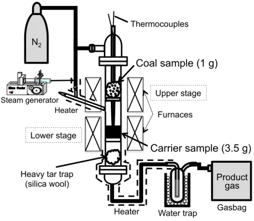
Steam reforming experiments were conducted in a two-stage fixed-bed quartz reactor with an internal diameter of 22 mm and a main body length of 880 mm. A schematic illustration of the experimental setup is shown in Figure 10. Prior to the experiment, a carrier sample of 3.5 g and a coal sample of about 1 g wrapped with silica wool were placed in the lower and upper stages, respectively. As a heavy tar trap, some amount of silica wool was also packed under the lower stage of the reactor, and a water trap was set at the outlet of the reactor as well.
Temperatures at the two stages were programmed and controlled individually by two electric furnaces. First, the oxygen carrier stage was heated to 1173 K in nitrogen flow of 60 ml·min-1 from the top of the reactor and maintained at that temperature throughout the experiment. Then, steam with nitrogen gas was introduced into the lower stage through the branch gas inlet at atmospheric pressure. The total gas flow rate from the central and branch inlets was adjusted to 120 ml·min-1 including steam. Here, S/C ratios of 0.5, 1.0, 1.5, and 2.5, corresponding to 9.5%, 19.0%, 28.5%, and 47.5% steam
in nitrogen, respectively, were chosen to investigate the effect of steam content on the reforming performance of the carrier. Steam reforming was then commenced with heating of the coal sample to 1173 K for 90 min at a heating rate of 10 K·min-1. Volatiles produced via pyrolysis of the coal reacted with steam and oxygen carrier in the lower stage.
Gaseous products collected in a gasbag were analyzed using offline gas chromatographs (GC-2014B, Shimadzu, Japan) with a thermal conductivity detector and a flame ionization detector equipped with a methanizer. Gas yield was calculated and presented as the molar amount of each gas component. At the end of the steam reforming experiment, the other carbonaceous products from coal volatiles such as soot and tar, left in the reactor and on the tar trap, were combusted separately in oxygen. The carbon molar yield of each product was determined from the combustion gases using gas chromatography analysis. The carbon balance is defined as the molar percentage of elemental carbon in each product out of the total carbon of the volatiles.
Figure 10. Schematic illustration of the experimental setup for the steam reforming experiments.
Furnaces N2
Thermocouples
Steam generator
Carrier sample (3.5 g)
Water trap Gasbag
Coal sample (1 g)
Heavy tar trap
(silica wool) Product
gas Heater
Heater
Upper stage
Lower stage
![Figure 2. The overview of CCS process, provided by Global CCS Institute [8]](https://thumb-ap.123doks.com/thumbv2/123deta/6224270.1090853/10.892.146.791.454.809/figure-overview-ccs-process-provided-global-ccs-institute.webp)
![Figure 4. Overview of CO 2 capture in power and industrial processes [7]](https://thumb-ap.123doks.com/thumbv2/123deta/6224270.1090853/16.892.154.775.118.474/figure-overview-capture-power-industrial-processes.webp)