Chaos Propagation and Synchronization in Coupled Chaotic Circuits with Star-and-Ring Combination
Takahiro Chikazawa, Shogo Tamada, Yoko Uwate and Yoshifumi Nishio Dept. of Electrical and Electronic Engineering, Tokushima University
2-1 Minami-Josanjima, Tokushima 770–8506, Japan Email:{chikazawa,tamada,uwate,nishio}@ee.tokushima-u.ac.jp
Abstract—In this study, we investigate chaos propagation and synchronization phenomena in coupled chaotic circuits with star- and-ring combination when one circuit is set to generate chaotic attractor and the other circuits are set to generate three-periodic attractors. Moreover, we observe how to propagate chaos and synchronization phenomena by increasing the coupling strength.
I. INTRODUCTION
Synchronization is one of the fundamental phenomena in nature and one of the typical nonlinear phenomena. Therefore, synchronization of coupled chaotic circuits has been interested by many researchers not only engineering but also the physical and biological fields [1]-[4]. In particular, it is important to investigate synchronization phenomena of coupled circuits under some difficult situations for the circuits. Additionally, it is applicable to the fields of medical science and biology and so on. As previous studies, synchronization and chaos propagation have been investigated in the ring or ladder of coupled chaotic circuits [5]-[7]. However, these studies were considered about the only one ring or ladder system.
In this study, we investigate chaos propagation and synchro- nization phenomena in coupled chaotic circuits with star-and- ring Combination. We propose a star-and-ring combination system using of 6 chaotic circuits coupled by the resistors.
In this model, one circuit is set to generate chaotic attrac- tor and the other circuits are set to generate three-periodic attractors. First, we observe how to chaos propagation by increasing the coupling strength. Moreover, by measuring the phase difference among all adjacent circuits, we investigate synchronization in the entire system.
II. SYSTEM MODEL
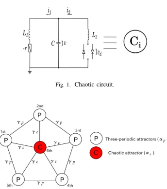
The chaotic circuit is shown in Fig. 1. This circuit consists of a negative resistor, two inductors, a capacitor and dual- directional diodes. We propose a star-and-ring combination system model in Fig. 2. In this system, 6th circuit generates chaotic attractor and the other circuits generate three-periodic attractors. In order to investigate the chaos propagation, we use two parameters of the coupling strength. Each circuit is coupled by the resistor.
i1 i2
L1
-r C v
vd L2
Ci
Fig. 1. Chaotic circuit.
P
P
P
P P
1st
2nd
3rd
5th 4th
C 6th
C
P Three-periodic attractors (αp ) Chaotic attractor (αc ) γp γp
γp
γp γp γc γc
γc γc γc
Fig. 2. Star-and-ring combination.
The circuit equations of this circuit are described as follows:
L1
di
dt=v+ri L2
di
dt=v−vd
Cdv
dt =−i1−i2,
(1)
The characteristic of nonlinear resistance is described as follows:
vd= rd 2
i2+ V rd
− i2− V
rd
. (2)
- 63 -
IEEE Workshop on Nonlinear Circuit Networks December 11-12, 2015
By changing the variables and parameters,
i1=
rC L1
V xn, i2=
√L1C L2
V yn, v=V zn
α=r rC
L1
, β= L1 L2
, δ=rd
√L1C L2
,
γ= 1 R
rL1
C , t=p L1C2τ,
(3)
The normalized circuit equations are given as follows:
dxn
dτ =αxn+zn
dyn
dτ =zn−f(yn) dzn
dτ =−xn−βyn− XN n=1
γij(zn−zn+1) (n= 1,2,· · ·, N).
(4)
In Eq. (4),N is the number of coupled chaotic circuits and γ is the coupling strength.f(yi)is described as follows:
f(yn) = 1 2
yn+1 δ
− yn−1
δ
. (5)
The coupling strength which connected with 6th isγc, and the others areγp. We defineαc to generate the chaotic attractor, and αp is defined to generate the three-periodic attractors.
For the computer simulations, we calculate Eq. (4) using the fourth-order Runge-Kutta method with the step size h = 0.01. In this study, we set the parameters of the system as αc= 0.460,αp= 0.412,β= 3.0andδ= 470.0.
III. SIMULATION RESULTS
A. Chaos propagation
Figure 3 shows the initial state when all circuits are not connected. We observe three-periodic attractors from 1st to 5th circuits and chaotic attractor in 6th circuit.
Figure 4 shows chaos propagation attractors when the coupling strengthγc is only conected from 6th to 5th circuit.
At this time, we fix the coupling strength as γc = 0.0007, and we increase coupling strength γp. The 5th circuit is only propagated the chaotic attractor of 6th chaotic circuit (see. Fig. 4(a)). The chaotic attractor of 5th circuit propagates to both side of the neighbor circuits (see. Fig. 4(b)). The states of all circuits become the chaotic attractors (see. Fig. (c)).
1st 2nd 3rd 4th 5th 6th
(a)γp=0.0000
z1
x1
z2 z3 z4 z5 z6
x2 x3 x4 x5 x6
Fig. 3. Chaos propagation (γc= 0.0000).
1st 2nd 3rd 4th 5th 6th
(b)γp=0.0010
(c)γp=0.0015 (a)γp=0.0007
z1
x1
z2 z3 z4 z5 z6
x2 x3 x4 x5 x6
z1
x1
z2 z3 z4 z5 z6
x2 x3 x4 x5 x6
z1
x1
z2 z3 z4 z5 z6
x2 x3 x4 x5 x6
Fig. 4. Chaos propagation (γc= 0.0007).
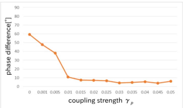
Figure 5 shows the relation between the phase difference and the coupling strength when the coupling strength γc is only conected from 6th to 5th circuit. At this time, we fix the coupling strength as γc = 0.0007, and we increase coupling strength γp. The phase difference shows the average among all adjacence circuits. If all circuits are not synchronized, the phase difference shows 60◦. We can confirm that the phase difference is smaller and comes close to0◦ by increasing the coupling strength.
As a result, three-periodic attractors are affected from chaotic attractor by increasing the coupling strengthγp.
Fig. 5. Relation between the phase difference and the coupling strength in star-and-ring combination.
B. Synchronization phenomena
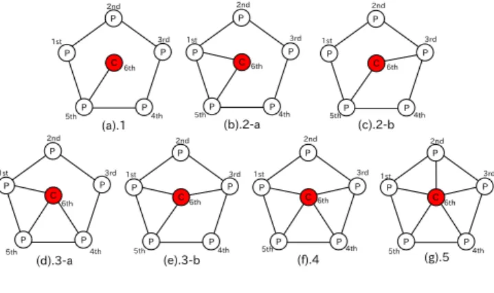
In this section, we confirm the variation of the phase difference, when we change the number of edges between 6th circuit and the other circuits. Figure 6 shows all system patterns in this star-and-ring combination by changing com- bination. For example, this model is connected to all circuits (see. Fig. 6(g)) and this model is only connected from 6th to 5th circuits (see. Fig. 6(a)). When we fix the coupling strength asγc= 0.007andγp= 0.005, the phase difference shows the average among all adjacence circuits in Table 1.
In order to investigate the phase difference, we consider that the entire system easy to reach the synchronous state by increasing the number of edge.
- 64 -
P P
P
P P
C P
P P
P P
C 1st
2nd
3rd
5th 4th 6th
P P
P
P P 1st
2nd
3rd
4th 5th
C6th
P
P P
P P
C P
P
P
P P
C
P
P
P P
C P
P
P
P P
C P 1st
2nd
3rd
4th 5th
6th
1st 2nd
3rd
5th 4th 6th
1st 2nd
3rd
5th 4th 6th
1st 2nd
3rd
5th 4th 6th
(a).1 (b).2-a (c).2-b
(d).3-a (e).3-b (f).4 (g).5
1st 2nd
3rd
4th 5th
6th
Fig. 6. System patterns.
TABLE I
PHASE DIFFERENCES IN ALL SYSTEMS.
patterns phase difference[◦] average phase difference[◦]
(a).1 56.11 56.11
(b).2-a 18.54
25.57
(c).2-b 32.59
(d).3-a 37.98
29.79
(e).3-b 21.60
(f).4 11.85 11.85
(g).5 9.06 9.06
IV. CONCLUSIONS
In this study, we have investigated chaos propagation and synchronization phenomena in coupled chaotic circuits as our proposed system. By the computer simulations, We have observed that the chaotic attractor is propagated to the other circuits. The three-periodic attractors are affected from the chaotic attractors when the coupling strength increase. More- over we consider that the phase difference close synchronous state by increasing the number of edge.
For the future works, we develop the network model into cubic and more complex. Considering the other network of chaotic circuits is important subjects for us.
REFERENCES
[1] N. F. Rullckov and M. M. Sushchik, “Robustness of Synchronized Chaotic Oscillations,” Int. J. Bifurcation and Chaos, vol. 7, no. 3, pp.
625-643, 1997.
[2] M. Wada, Y. Nishio and A. Ushida, “Analysis of Bifurcation Phenom- ena in Two Chaotic Circuits Coupled by an Inductor,” IEICE Trans.
Fundamentals, vol. E80-A, no. 5, pp. 869-875, 1997.
[3] Y. Nishio and A. Ushida, “Chaotic Wandering and its Analysis in Simple Coupled Chaotic Circuits,” IEICE Trans. Fundamentals, vol. E85-A, no.
1, pp. 248-255, 2002.
[4] G. Abramson, V.M. Kenkre and A.R. Bishop, “Analytic Solutions for Nonlinear Waves in Coupled Reacting Systems,” Physica A: vol. 305, no. 3-4, pp. 427-436, 2002.
[5] Y. Uwate and Y. Nishio, “Collision between Chaotic and Periodic Attractors in a Ring of Coupled Chaotic Circuits” Proceedings of International Conference on Nonlinear Dynamics of Electronic Systems (NDES’12), pp. 66-69, Jul. 2012.
[6] Y. Uwate and Y. Nishio, “Chaos Propagation in a Ring of Coupled Cir- cuits Generating Chaotic and Three-Periodic Attractors” Proceedings of IEEE Asia Pacific Conference on Circuits and Systems (APCCAS’12), pp. 643-646, Dec. 2012.
[7] Y. Uwate, T. Ott and Y. Nishio,“Clustering Phenomena in Coupled Chaotic Circuits with Different Coupling Strength” Proceedings of European Conference on Circuit Theory and Design (ECCTD’13), DOI:10.1109/ECCTD.2013.6662220 (4 pages), Sep. 2013.
- 65 -