Kansai Photon Science Institute
Quantum Beam Science Research Directorate National Institutes for
QST-M-25
A NNUAL R EPORT
2019
Contents
Preface 1
Activities of KPSI 3
User Facilities 9
Research Highlights 15
Publication List 57
The Kids’ Science Museum of Photons 71
Appendix 83
はじめに
本年報では、関西光科学研究所(以下、関西研)において 2019 年度に実施された研究開発の主だ った成果を紹介しています。関西研は国立研究開発法人量子科学技術研究開発機構(以下、量研)の 研究開発拠点であり、けいはんな学研都市にある京都府木津地区と兵庫県播磨地区の2か所に研究サイ トを持っています。そこでは、研究系職員約 80 名及びそれを支える技術系・事務系スタッフを含めて総勢約 150 名のスタッフが、量研における関西研のミッションである「レーザーや放射光による光科学技術の研究開 発」を推進しています。木津地区では、世界トップレベルの高強度レーザー技術を基盤としたレーザー加速や X線発生等のレーザー駆動の新しい放射線源開発、レーザーの短パルス性を活かした超高速計測技術開 発、そして放射線影響や創薬に資する量子生命科学の最先端の研究開発を実施しています。また、播磨 地区では、大型放射光施設 SPring-8 に 2 本の専用ビームラインと計算機シミュレーションを活用すること で、新しい放射光X線利用技術開発と物質材料科学の最先端研究を展開しています。2019 年度からは、
量研の組織改変に伴って量子生命科学領域が発足し、その分野に関連する2つの研究グループが本部直 轄の研究領域に移りましたが、関西研全体としては、これまで通り、量研の成果最大化に向けて最大限努め て参りたいと思います。
木津地区のレーザー科学分野においては、次世代の高強度レーザーを支える励起光源の安定化や、パラ メトリック増幅を用いた新しい発振器の提案がなされました。また、レーザーイオン加速研究においては照射強 度と加速エネルギーの新しい関係性の解明、そして、量子生命科学領域においては、単一分子を対象として DNA 損傷を直接観察する試み等の新たな知見が生まれています。また、播磨地区においても、共鳴非弾 性散乱法による銅酸化物超伝導体の電子励起の詳細な観察や、幾何学的にフラストレーションを内包する 三角格子磁性体の磁気特性の理論考察など、数多くの優れた成果を挙げています。さらに、光技術の実用 化の観点からは、非侵襲血糖値測定やレーザーによるトンネル検査技術の実用化に向けた取組を引き続き 行っています。
関西光科学研究所は、「光」を通じた我が国の量子科学技術の発展とイノベーション戦略に貢献する開 かれた研究拠点としての役割を果たすべく、今後とも職員一同、より一層努力してまいります。皆様のご理 解・ご協力を宜しくお願い申し上げます。
2020 年吉日 関西光科学研究所 所長 河内 哲哉
Preface
This annual report from the Kansai Photon Science Institute (KPSI) provides highlights of the scientific and technical research that was conducted over the 2019 fiscal year.
KPSI is one of the research and development (R&D) bases of the National Institute of Quantum and Radiological Science and Technology (QST). At KPSI's two R&D sites—the Kizu site in Keihanna Science City in Kyoto Prefecture and the Harima site in Hyogo Prefecture—there are around 150 staff, comprising around 80 researchers and the technical and administrative staff who support them. We promote the R&D of optical science and technology using lasers and synchrotron-radiation X-rays, which is the mission of KPSI at QST. At the Kizu site, we are conducting state-of-the-art research such as developing new types of laser-driven radiation sources, such as laser-accelerated particle beams and ultrashort X-rays based on world-leading top-class high-intensity laser technology, ultrafast measurement methodology using ultrashort pulse technology, and quantum life science that helps us to understand radiation effects and to develop new medicines. At the Harima site, using the two contract beamlines of SPring-8 and computer simulations, we are developing new technology to utilize synchrotron-radiation X-rays and carrying out state-of-the-art research in materials science. From FY2019, QST organized a new institute, the Institute for Quantum Life Sciences, under the direct control of the president, and two research groups related to this research field have been transferred to this new institute while keeping their location at KPSI. However, KPSI will continue to support all the research groups to maximize the results of QST.
In the laser science field at the Kizu site, we have developed an optically synchronized stable pump laser and a new optical parametric oscillator, which will become seed technologies toward next-generation high-power lasers. In laser-driven ion acceleration research, we have firstly revealed the relationship between laser intensity and accelerated ion energy by taking the effect of the spot size into account. In the field of life sciences, new findings have been obtained through attempts to directly observe DNA damages for single molecules. At the Harima site, we obtained several excellent results such as detailed observation of electronic excitation of copper-oxide superconducting substances using resonant inelastic X-ray scattering and theoretical investigation of the magnetic properties of substances on a triangular lattice system, which may include geometrical frustration. In addition, regarding the social implementation of optical technology, we are making efforts toward practical application of non-invasive blood glucose measurement and laser-based tunnel inspection technology.
KPSI will continue to fulfill its role as an open research center of the "science of light" and will contribute to quantum science and technology and the strategy for innovation in Japan. We appreciate your understanding and cooperation.
Good day, 2020 Director General of KPSI Tetsuya KAWACHI
Activities of KPSI
関西光科学研究所の主な動き
【シンポジウム・研究会等の開催】
2019
年
6月
12日
「光・量子ビーム科学合同シンポジウム
2019」(阪大・銀杏会館、大阪府吹田市)
大阪大学と量研との間で締結された包括協定に 基づき、合同シンポジウムを開催しました。参 加者は約
200名であり、招待講演・口頭発表、
ポスター発表、若手ポスター賞表彰式、意見交 換会が行われました。
2019
年
7月
8日
「レーザー・物質相互作用における非線形応答ミニワークショップ」 (関西研、京都府木津川市)
CREST「光・電子融合第一原理ソフトウェアの開発と応用」と Q-LEAP(ALICe)「次世代レーザー」が
主催する“物質とレーザーの非線形相互作用に関するミニワークショップ”が
35名の参加者によって木津 地区にて行われました。国内外の研究者が発表・議論を行いました。
左:ワークショップの様子、右:参加者集合写真(ITBL 棟)
2019
年
8月
30、31日
「SPring-8 シンポジウム
2019」(岡山県岡山市)
岡山大学において、 「次の
20年に向けての一歩」と題して、
SPring-8が次の
20年後も利用者にとって 魅力的な放射光施設であり続けるための具体的な取り組みや仕組みをテーマとして開催されました。
シンポジウム会場の様子(岡山大学、写真提供:SPring-8 シンポジウム
2019事務局)
左:シンポジウム開催案内版
右:若手ポスター発表賞表彰の様子
2019
年
12月
4、5日
「第
3回
QST国際シンポジウム」 (奈良春日野国際フォーラム甍、奈良県奈良市)
昨年に引き続き、奈良春日野国際フォーラム甍(奈良県奈良市)にて国際シンポジウムを行いました。
今回のテーマは「Quantum Life Science (量子生命科学) 」で、
208名の参加者が集いました。
Luke Lee博士(カリフォルニア大学バークレー校/ USA) 、Murali Krishna Cherukuri 博士(NIH/ USA)による 基調講演をはじめ、国内外の研究者による
5つのセッションの他、ポスター発表
56件が行われました。
2020
年
1月
10-12日
「第
33回日本放射光学会年会・放射光科学合同シンポジウム」 (愛知県産業労働センター)
本シンポジウムは放射光を利用した研究成果、放射光用の加速器、光源、ビームライン、測定器の技術開 発、放射光施設運営も含めた放射光施設と利用に係る総合的な発表と議論の場となっています。量研から も、次世代放射光施設計画の企画講演や施設報告のほか、稲見上席研究員が発見した新しい
X線磁気光 学効果の理論的研究(小出博士研究員)や、同効果を応用した磁気光学顕微鏡開発(菅原技術員)の発表 など、多数の発表が行われました。
左:メインホールの様子
(写真提供:JSR2020 事務局)
右:ポスターセッションと企業展示の様子
(写真提供:JSR2020 事務局)
2020
年
2月
13、14日
「第
3回 理研光量子工学研究センター・量研関西光科学研究所合同セミナー」 (三重県伊勢市)
毎年
RIKEN-RAPと
QST-KPSIが合同で行っているセミナーを「伊勢かぐらばリゾート千の杜」にて開
催いたしました。22 名の参加者があり、レーザー開発から応用にいたる研究について、2 日間にわたる
合宿形式のセミナーを行いました。
左:参加者集合写真、右:セミナーの様子
【施設公開】
第
27回 SPring-8/SACLA 施設公開
4
月
27日(土)に恒例の
SPring-8/SACLA施設公開が大型放射光施設 SPring-8 (兵庫県佐用郡佐用町)
で開催されました。施設公開では、普段なかなか入ることのできない蓄積リング棟の見学や、講演会の聴 講、実験の体験ができるだけでなく、地元特産品などの販売も行われました。今年は親子連れや学生さん を中心に 2,056 名の方が参加されました。
関西光科学研究所(木津地区)施設公開
10
月
27日(日)に関西光科学研究所(木津地区)の施設公開を開催しました。1148 名の方々にご来場 いただき、世界トップクラスの高強度レーザー施設見学や、光の実験ショー、高校生や大人も楽しめるサ イエンスカフェ、木津南中学吹奏楽部の演奏会等を行いました。木津地区の施設公開は例年
10月最終日 曜日に行っております。
左:ふぉとんくんがお出迎え、右:関西研(木津地区)施設公開当日のスタッフ集合写真
展示実験を楽しむ来場者の皆様(播磨地区)
【主な出展等イベント】
QST
関西光科学研究所では、2019 年度も積極的にアウトリーチ活動を実施しました。 「きっづ光科学館 ふぉとん」の年間来場者は
50,963人を達成しました。(ただし
COVID-19感染症対策のために
2020年
2月
27日からは臨時休館中です。2020 年
3月
31日現在)
4
月
7日 「第
42回花と緑の見学会」出展(QST 高崎量子応用研究所、群馬県高崎市)
7
月
7-10日 「第
19回
SPring-8夏の学校」開催(大型放射光施設
SPring-8、兵庫県佐用町))7
月
13、14日 「大阪科学技術館 テクノくん夏祭り
2019」サイエンスショー&科学工作(大阪科学技術館、大阪府大阪市)
7
月
20、21日 「姫路・桜山公園まつり 科学の屋台村」出展 姫路市桜山公園(兵庫県姫路市)
7
月
25日 「夏休み
2019宿題自由研究大作戦」サイエンスショー&科学工作(みやこメッセ京都、京 都府京都市)
7
月
27、28日「青少年のための科学の祭典
2019全国大会」出展(科学技術館、東京都千代田区)
9
月
22日「核融合とレーザー 作る・体験する・学ぶ」サイエンスショー・科学工作(大阪市中央公会堂、
大阪府大阪市)
10
月
3、4日「京都スマートシティエキスポ
2019」、 「第
13回けいはんなビジネスメッセ
2019」同時開催への出展(けいはんなオープンイノベーションセンター、京都府相楽郡精華町)
10
月
17日 「播磨高原東中学校出前授業」 (播磨科学公園都市、兵庫県たつの市)
10
月
31日-11 月
2日「けいはんな情報通信フェア
2019」出展(けいはんなプラザ、京都府相楽郡精華町)
2020
年
1月
29-31日 「第
19回国際ナノテクノロジー総合展・技術会議(nano tech 2020)出展(東 京ビックサイト、東京都江東区)
左:第
19回
SPring-8夏の学校参加者の全体集合 写真(写真提供:高輝度光科学研究センター)
右: 「核融合とレーザー 作る・体験する・
学ぶ」サイエンスショー・科学工作の様子
User Facilities
主要な施設・装置
木津地区
〇J-KAREN レーザー装置
【装置概要】
世界トップクラスの極短パルス超高強度レーザーです。30J のレー ザーエネルギーを
30フェムト秒(1 フェムトは
1000兆分の
1)の時間に閉じ込めることにより
1000兆ワットの超高強度を実現します。
(右の写真は強力な励起レーザーの光で緑色に光っています。)
【装置性能】
・照射エネルギー:30 J/pulse
・コントラスト比:10
-12・波長:800 nm
・繰り返し:0.1 Hz
・パルス幅:30 フェムト秒
・集光強度:10
22 W/cm2【主要な研究課題】
レーザーの高度化技術の開発、イオンおよび電子のレーザー加速技術の開発、高エネルギーコヒーレ ント
X線の発生等
〇X 線レーザー実験装置 休止中
〇QUADRA-T レーザーシステム
【装置概要】
1
秒間に
1000発のレーザーパルスが繰り出せる高平均出力ピコ秒 パルスレーザーです。中心周波数
0.3 THzの高強度テラヘルツパルス を発生することが可能です。
【装置性能】
・照射エネルギー:10 mJ/pulse
・波長:1030 nm
・繰り返し:1 kHz
・パルス幅:約
1ピコ秒
【主要な研究課題】
高繰り返し高出力レーザー(パラメトリック増幅器等)の開発、高強度テラヘルツ光源の開発
播磨地区
播磨地区では大型放射光施設
SPring-8に
2本の
QST専用ビームラインを設置しているほか、日本原
子力研究開発機構(JAEA)の専用ビームラインにも複数の放射光専用実験装置を常設しています。一方
で、QST 専用ビームラインにも、JAEA の専用実験装置が常設されています。
〇BL11XU(QST 極限量子ダイナミクスⅠビームライン)
【装置概要】
SPring-8
標準の真空封止アンジュレータを光源とし、マルチ結晶交換システムを装備することで、
広範囲のエネルギー領域の高輝度放射光
X線を高効率に利用できるビームラインです。
【装置性能】
・光源:真空封止アンジュレータ
・エネルギー領域:6~70 keV
・分光結晶:Si(111)、Si(311)
・実験装置:放射光メスバウアー分光装置、共鳴非弾性
X線散乱装置、及び表面
X線回折計
1.放射光メスバウアー分光装置
57Fe、61Ni
等のメスバウアー核種を対象とした放射光メスバウアー分光が 可能で、物質の電子、磁気状態から格子振動状態に関する情報などを得るこ とができます。
2.
共鳴非弾性
X線散乱装置
2m
長アームに搭載した球面湾曲型集光式アナライザー結晶による背面反 射を用いることで、高分解能の
X線分光を行い、散乱光の方位や入射光との エネルギー差から、運動量移行を伴う固体内素励起が観察できます。
3.
表面
X線回折計
分子線エピタキシー(MBE)チェンバーを搭載した表面構造解析用装置 で、窒化物を含む半導体結晶などの成長過程を、
X線回折法を用いてその場 観察・リアルタイム観察することができます。
【主要な研究課題】
金属薄膜の原子層単位での磁性探査、白金系燃料電池触媒の電子状態解析、
半導体量子ドットや半導体多層膜の成長過程のリアルタイム解析
〇BL14B1(QST 極限量子ダイナミクスⅡビームライン)
【装置概要】
偏向電磁石を光源とすることで、連続スペクトルを持つ白色
X線や高エネルギーの単色
X線が利用 可能なビームラインです。全反射ミラーや分光結晶の曲げ機構によって、試料位置への集光が可能とな っています。
【装置性能】
・光源:偏向電磁石
・エネルギー領域:白色
X線(5~150 keV) 、単色
X線(5~90 keV)
・実験装置:高温高圧プレス装置、分散型
XAFS測定装置(JAEA)及び
κ(カッパー)型回折計(JAEA)
1.
高温高圧プレス装置
高温高圧の条件下にある試料を、白色
X線を用いたエネルギー分散型
X線回折 法やラジオグラフィー法、単色
X線を用いた
XAFS(X線吸収微細構造)法や角度 分散型
X線回折法によって調べることができます。
【主要な研究課題】
高圧下での金属水素化物形成過程のその場観察
2. 汎用四軸X
線回折計
令和
2年
3月に
RI実験棟から移設。令和
2年度からビーム利用実験に向けて、
試験調整等を行う予定です。
【主要な研究課題】
残留応力評価等、様々な研究に活用予定。
〇BL22XU(JAEA 専用ビームライン)における放射光専用実験装置
1.単色
X線実験用高温高圧プレス装置(JAEA
BL22XU)高温高圧下(到達圧力
10 GPa(10万気圧)、到達温度
2000 K程度)の
X線回折測定や
X線吸収法を用いた密度測定、室温、1 MPa 未満の水素ガ ス雰囲気中でのその場
X線回折観察、時分割
X線回折測定が可能な装置で す(令和
2年
7月に放射光物性研究棟に移設)。
2.
ダイヤモンドアンビルセル回折計(JAEA
BL22XU)大型イメージングプレート検出器と高エネルギーX 線を利用することに より、高圧下での単結晶
X線回折及び粉末
X線回折実験、X 線全散乱測定 及び原子二体分布関数(PDF)解析が可能な装置です。
3.
大型
X線回折計
共鳴
X線散乱による電子軌道状態の観測、スペックル回折によるドメイ ン構造の研究、応力・歪み分布測定などの回折マッピングなど多目的に利 用する四軸回折計です。
【主要な研究課題】
水素貯蔵合金の水素吸蔵過程の時分割その場
X線回折測定、負の熱膨張材料、超伝導体、
f電子系化 合物、コヒーレント
X線を利用したスペックル散乱によるナノドメイン観察。応力・歪みの
3次元分 布測定、等
施設の稼働実績
〇 木津地区
実施課題件数
装置名称 独自研究 受託研究 共同研究 施設共用
J-KAREN
レーザー装置
3 3 4 4X
線レーザー実験装置
0 0 0 0QUADRA-T
レーザーシステム
1 0 0 0kHz
チタンサファイアレーザー
8 1 1 0X
線回折装置
1 0 1 0内部利用
(共同研究を含む)
69%
施設共用 10%
メンテナンス 21%
内部利用
(共同研究を含む)
57%
メンテナンス 43%
内部利用
(共同研究を含む)
90%
メンテナンス 10%
〇 播磨地区
2019
年度の
SPring-8蓄積リングの運転時間は約
5280時間で、放射光利用時間はそのうちの約
4584時間でした。量研、原子力機構とも専用ビームラインでは
10~20%弱程度の調整時間を除き、放射光利用時間で独自研究や受託研究、外部利用者への施設共用と研究支援を行っています。
実施課題件数
ビームライン 独自研究 受託研究 共同研究 施設共用
BL11XU 8 0 4 21
BL14B1 7 0 5 12
BL22XU 5 0 3 9
利用日数
ビームライン 独自研究 受託研究 共同研究 施設共用
BL11XU 81 0 28 61
BL14B1 33 0 17 38
BL22XU 0 0 23 24
施設の利用状況
〇木津地区
J-KARENレーザー装置
(合計ビームタイム:1752時間)
その他装置(木津地区)
(合計ビームタイム:1390時間)
QUADRA-Tレーザー装置
(合計ビームタイム:232時間)
〇播磨地区
QST極限量子ダイナミクスⅠビームライン(BL11XU) QST極限量子ダイナミクスⅡビームライン(BL14B1)
JAEA重元素科学Ⅰビームライン(BL22XU) JAEA重元素科学Ⅱビームライン(BL23SU) QST成果非公開
1.7%
JAEA内部課題 3.4%
QST外部課題 32.3%
QST内部課題 62.5%
QST内部課題 30.5%
QST外部課題 22.0%
JAEA内部課題 32.1%
JAEA外部課題 15.4%
QST内部課題 16.6%
QST外部課題 16.6%
JAEA内部課題 49.7%
JAEA外部課題 15.9%
JAEA成果非公開 1.4%
QST内部課題 14.8%
JAEA内部課題 47.4%
JAEA外部課題 37.4%
JAEA成果非公開 0.4%
Research Highlights
Activities of Advanced Photon Research
Kiminori Kondo
Department of Advanced Photon Research
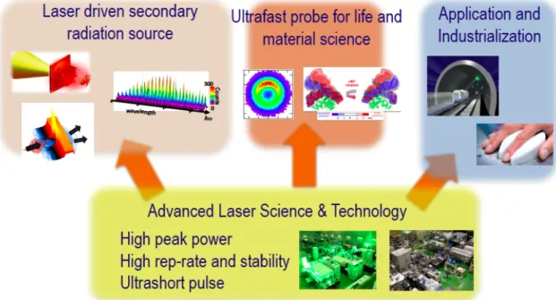
In the department of Advanced Photon Research, the primary research focus is the science and technology of advanced lasers. High-peak-power laser technology, high-repetition-rate and high-stability laser technology, and ultrashort-pulse technology are of particular importance. We develop these technologies in-house and apply them to various objects. The largest laser system in KPSI is the Petawatt (PW)-class high- peak-power laser J-KAREN-P. This system has been upgraded since obtaining the supplementary budget in FY2012, and the long commissioning operation term was completed two years ago.
Internal users in KPSI and external users have used the system in PW-class operation mode. In this fiscal year, 30% of the total machine time has been shared to the external users. The extreme focused intensity of up to 1022 W/cm2 on targets with extremely high-contrast suppression of the proceeding optical component to the main pulse is now available. This extreme status of our high- power laser infrastructure is maintained by the laser facility operation office, advanced laser group, and high-intensity laser science group. The advanced laser group not only maintains J- KAREN-P to deliver laser pulses with the best conditions, but also develops and introduces new technology to maintain the world-leading class condition of J-KAREN-P. Dr. Miyasaka reports the development of the optically synchronized stable pump laser for optical parametric chirped pulse amplification (OPCPA) and Dr. Ogura reports the investigation on the recovery time of semiconductor saturable absorption, which is important for taking the high quality high peak power laser pulse. The high- intensity laser science group mainly studies laser-driven ion acceleration, laser electron acceleration, and relativistic high- order harmonic generation with J-KAREN-P in KPSI.
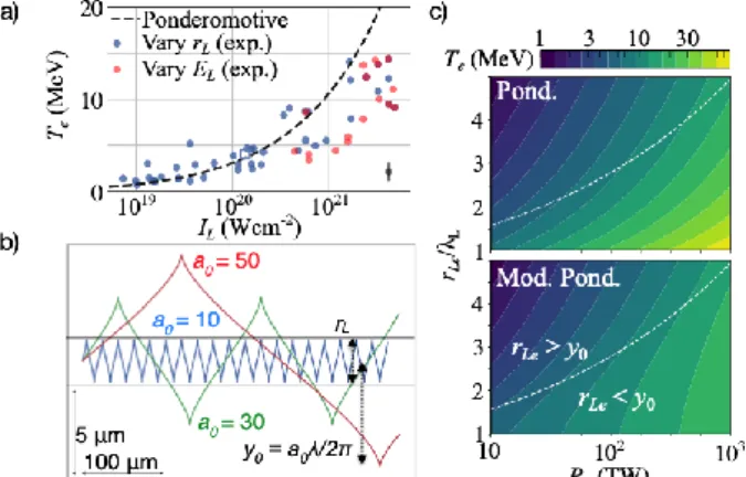
One of the most important applications is the development of a laser-driven secondary radiation source. An extremely high optical field can be formed with focusing extremely high peak power to an ultimately small spot size. Atoms and molecules exposed to this extremely high field are immediately ionized by field ionization. The corresponding optical intensity to the atomic unit is only 3 × 10¹⁶ W/cm2, which is much lower than that generated with J-KAREN-P. The generated free electrons move along the extremely high optical field, then the ultra-relativistic quiver motion is induced. These energetic quivering electrons induce the generation of various secondary radiations. This means that there is a possibility of a compact energetic quantum beam source without conventional accelerator technology. If this technology is established and applied to various fields, a type of destructive innovation could occur. Dr. Dover explains the effect of small focus on electron heating and proton acceleration in ultra-relativistic laser-solid interactions, which is very important knowledge for designing the high field interaction experiment and for developing the laser driven ion accelerator. Laser driven electron acceleration is also an important topic related to this interaction. Dr. Kai describes the variation in electron emission time in weakly nonlinear laser wakefield. One of the most important applications of laser-driven energetic particles is the application to Quantum Scalpel, which is a new-generation heavy-ion cancer therapy machine planned to be developed within 7 years from now. Quantum Scalpel is the one of the main projects in QST. The injector part of Quantum Scalpel is based on the laser-driven carbon accelerator. The JST-MIRAI R & D program (large-scale type) started in Nov. 2017. The aim of this program is to show a proof of concept (POC). In addition to an
Fig. 1 Research and development of the department of Advanced Photon Research.
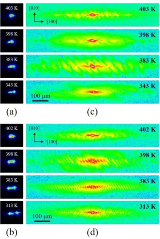
ion accelerator, a laser plasma electron accelerator is also under development in KPSI within the MIRAI program. Furthermore, particle acceleration and X-rays are generated with ultrashort high-peak-power lasers. Burst intensification by singularity emitting radiation (BISER) is the new laser-driven coherent X- ray generation scheme, which has been invented by KPSI. There is also a possibility of a keV-scale coherent X-ray source that doesn’t use a gigantic linac like such as SACLA with BISER. The development of high repetition rate secondary sources is very important for the real application of these secondary radiation sources. In the MIRAI project, the demonstration of POC of the laser driven heavy ion injector must be shown by the end of FY2026. Therefore, the X-ray laser group once shut down the 0.1 Hz X-ray laser driver (TOPAZ) and started to develop the high quality 10 Hz X-ray laser driver. This system is established on the commercial base 10 TW/10 Hz CPA Ti:sapphire laser system. For taking the stable operation, the front end of this system is based on the 100 Hz LD pump solid state laser. By taking the double CPA structure, very high quality 30 TW laser pulses will be generated not only for 10 Hz X-ray laser operation, but also for the stable ion beam generation for the MIRAI project. As an application of the intense X-ray laser, Dr. Ishino reports the study on the mesoscopic polarization structure in the relaxor ferroelectrics Pb[(Mg1/3Nb2/3)1-xTix]O3.
The next important application of advanced laser science and technology is an ultrafast probe for life and material science.
THz radiation is also mainly developed in the ultrafast dynamics group for material science. Until two years ago, the C-Phost project had been performed by the ultrafast dynamics group.
Strong THz radiation is generated with a kHz 10-mJ ps laser system, QUADRA-T. These radiation and laser systems are used for various ultrafast dynamics research. Dr. Tsubouchi reports a study on the plane shockwave generation in liquid water using irradiation of THz pulses. Dr. Endo details the characterization of UV pulses by plasma-mirror FROG using a liquid-sheet jet of water. For life science applications, a bright and stable short pulse laser system has been developed and applied to the two-photon microscope for observing the neuron dynamics in mouse brains at NIRS. This research began to demonstrate one of the featured results by the unification of NIRS and JAEA three years ago. In
this fiscal year, for approaching a deeper component, a three- photon microscope is under development. Related to this development, Dr. Nagashima reports on the optical parametric oscillator pumped by the femtosecond Yb-doped fiber laser.
Moreover, the ultrashort probe started to be upgraded to the attosecond regime to start attosecond science in KPSI. The related study of CPS laser fabrication has also been on going.
These studies are supported by the Q-LEAP program which started two years ago. This project will be studied by the ultrafast dynamics group and the X-ray laser group. The X-ray laser group studies the interaction between intense X-rays and solid materials with the laser–plasma-based X-ray laser at KPSI and SXFEL at SACLA. The intense X-ray fabrication technology is an important fine structure fabrication technology, which has advanced to current laser fabrication technology. Dr. Dhin reports the strong excitation of silicone as a step towards sub-nanometer processing, which is very important for future processing.
In a sense, the most important application of our advanced laser science and technology is industrialization. In fact, from this fiscal year, the new SIP program, which follows the previous SIP program that finished two years ago, for the development of nondestructive tunnel inspection technology has started. This technology is being tested for its application to commercial technology at the venture company Photon-Labo. One of the key tools of the nondestructive tunnel inspection technology is the high-average-power high-repetition-rate intense laser technology.
This technology is used for hitting the inner surface of the concrete tunnel to induce an acoustic wave inside the wall. To induce an acoustic wave of sufficient amplitude, a 5-J per pulse with a 50-Hz repetition rate system has been developed and successfully loaded onto an inspection vehicle. This technology is closely related to the development of high-average-power high- peak-power laser systems, which could be used in the laser- driven carbon ion injector in Quantum Scalpel. Medical applications are an additional important consideration. By using high power laser technology, a strong and compact infrared laser can be developed for various medical use including detecting blood glucose measurement. Additionally, Dr. Aoyama introduced the potential application to the field of pathology.
Investigation of recovery dynamics of a semiconductor saturable absorber for
ultra-high-intensity lasers Koichi Ogura
Advanced Laser Group, Department of Advanced Photon Research
The short-pulse high-intensity laser system J-KAREN-P [1]
of the Kansai Institute of Photon Science is a petawatt-class laser system that can generate high-intensity light pulses with a pulse width of 30 fs, pulse energy of 40 J, and repetition rate of 0.1 Hz.
The short-pulse high-intensity laser has pre-pulses. The intensity ratio between the main pulse and the pre-pulse is called a temporal contrast. The temporal contrast of J-KAREN-P is approximately 1012. A high temporal contrast is required for accessing high-field physics in a desired target. The focus intensity of J-KAREN-P is up to 1022 W/cm2. This laser system is used for high-energy ion-generation experiments [2], electron acceleration experiments [3], and X-ray harmonic generation experiments [4]. These experiments are supported by J-KAREN- P’s high temporal contrast and focus intensity. The high temporal contrast is achieved by pulse cleaning methods in this laser system. One is a method with a temporal filter (a saturable absorber) and the other is a method using an optical parametric amplification method (OPCPA). Semiconductor-doped glass, RG850, is used as a saturable absorber to enhance the temporal contrast of the J-KAREN-P laser.
In this report, we report on the measurement of the recovery dynamics of the saturable absorber RG850 for a pulse cleaner.
Saturable absorption is an example of a nonlinear optics effect.
Saturable absorption can be described as a phenomenon where an initially dark piece of optical material becomes lighter when placed under a bright light. The saturable absorber RG850 absorbs a low-intensity pre-pulse, but transmits an intense main pulse of a short-pulse high-intensity laser beam. RG850 is a semiconductor-doped glass, being composed of a glass and small semiconductor crystals, and it has a fast response time.
RG850 is a material in which small crystalline semiconductor particles (CdS, CdTe, ZnS) are dispersed in silica- based glass. It is usually used as a color filter for light near 850 nm. The wavelength range of J-KAREN-P is around 775 nm to 825 nm with a center wavelength near 800 nm. The recovery dynamics of RG850 with a high laser intensity of 3 mJ/cm2 have not reported.
The diameters of the crystals are up to approximately 100 nm. The crystal is also called a quantum dot. The crystal is made by mixing glass with the composite semiconductor material and keeping the glass at an appropriate temperature. When the quantum dots are irradiated with light, hole–electron pairs are generated in the quantum dots and recombine with a certain relaxation time.
The band gap of bulk CdTe is 1.44 eV. It corresponds to a wavelength of 861 nm. Photons with a wavelength shorter than 861 nm are absorbed. The smaller the size of a quantum dot, the larger the energy gap grows compared to the bulk band gap energy. Therefore, it is possible to absorb the light of J-KAREN- P.
The total carrier recombination lifetime is the summation of the surface recombination lifetime and bulk recombination
lifetime [6]. The bulk recombination includes the radiative recombination and Auger recombination [6]. The bulk recombination lifetime is dependent on the carrier density, while surface recombination is not dependent on the carrier density [6].
It is related to the parameters of the semiconductor-doped glass (thermal diffusivity, etc.).
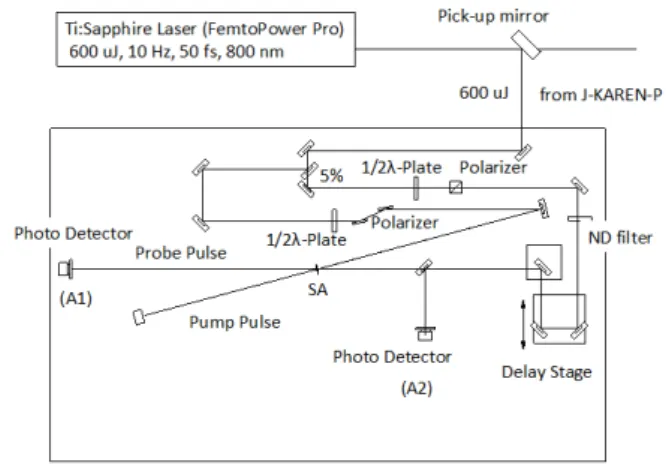
In this experiment, an ultrafast time-resolved pump-probe absorption technique is used to measure the time-dependent optical absorption of RG850. The experimental setup is shown in Fig. 1. In this method, the time resolution of the experiment depends on the pulse duration of the laser. In our case, the pulse duration is approximately 50 fs.
The laser (10 Hz, ~600 μJ, 50 fs) used in the experiment is a FemtoPower Compact Pro (Spectra-Physics), which is the front- end of the J-KAREN-P laser. The laser pulse was divided into pump pulses and probe pulses with a beam sampler. The energy of the pump pulse was changed with a wave-plate and polarizer system and neutral density filters.
The RG850 glass (1 inch diameter, 3 mm thickness) was irradiated with the pump beam (5 mm radius, 350 μJ energy). A delayed probe pulse was incident at the same position as the pump beam on the RG850. When the probe pulse closely followed the pump pulse (i.e., with only a slight time delay), the maximum transmittance of the probe pulse was obtained. The laser was operated at 10 Hz. The RG850 glass had completely recovered within 100 ms.
The transmitted probe energy was detected with a silicon photodiode (A2). The probe pulse energy was monitored with another silicon photo diode (A1). We obtained a normalized transmitted probe pulse energy (A1/A2) from the two silicon photo detectors.
It was found that the fast recovery time constant of RG850 was approximately 10 ps and the slow recovery time constant was
Fig. 1. Experimental setup.
approximately 500 ps, as shown in Fig 2. Here, τ1 corresponds to the bulk recombination lifetime and τ2 corresponds to the surface recombination time [6]. The bulk recombination time is dependent on the carrier density. If the focus intensity increases, the bulk recombination time will decrease. However, damage to the glass might be produced at a higher focus intensity.
Acknowledgments
The author thanks H. Kiriyama, Y. Miyasaka, A. Sagisaka, Y.
Fukuda and A. Pirozhkov for fruitful discussions.
References
1. H. Kiriyama, M. Mori, A. S. Pirozokov, K. Ogura, A.Sagisaka, A. Kon, T. Zh. Esirkepov, Y. Hayashi, H.
Kotaki, M. Kanasaki, H. Sakaki, Y. Fukuda, J. Koga, M.
Nishiuchi, M. Kando, S. V. Buranov, K. Kondo, P. R.
Bolton, O. Stezak, D. Vojna, M. Sawicka-Chyla, V.
Jambunathan, A. Lucianetti, and T. Mock, IEEE Sel. Topics J. Quantum Electron (Invited Paper) 21 (2015) 1601118.
2. A. S. Pirozokov, Y.Fukuda, M. Nishiuchi, H. Kiriyama, A.
Sagisaka, K. Ogura, M. Mori, M. Kishimoto, H. Sakaki, N.
P. Dover, K. Kpmdo, N. Nakanii, K. Huang, M. Kanasaki, K. Kondo, and M. Kando: Opy. Exp. 25 (2017) 20486.
3. M. Nishiuchi, H. Kiriyama, H. Sakaki, N. D. Dover, K.
Kondo, A. S. Pirozokov, A. Sagisaka, Y. Fukuda, K.
Nishitani, T. Miyahara, K. Ogura, M. A. Alkhimova, T. A.
Pikuz, A. Ya Faenov, Y. Watanabe, J. Koga, S. V, Bulanov, M. Kando, and K. Kondo: Proc. SPIE 10241 (2017).
4. A. S. Pirozhkov, M.Kando, T. Zh. Esirkevov, P. Gallegos, H. Ahmed, E. N. Ragozin, A. Ya. Faenov, T. A. Pikuz, T.
Kawachi, A. Sagisaka, J. Koga, M. Coury, J. Green, P.
Foster, C. Brenner, B. Dromey, D. R. Symes, M. Mori, K.
Kawase, T. Kameshima, Y. Fukuda, I. Chen, I. Daito, K.
Ogura, Y. Hayashi, H. Kotaki, H. Kiriyama, H. Okada, N.
Noshimori, T. Imazono, K.Kondo, T. Kimura, T. Tajima, H.
Daido, P. Reajeev, P. MaKenna, M. Borghesi, D. Neely, Y.
Kato, and S. V.Bulanov: New J. Phys. 16 (2014) 093003.
5. M. A. Alkhimova, A. Y. Faenov, I. Y. Skobel, T.A.Pikz, M.
Nishiuchim, H. Sakaki, A. S. Pirozhkov, A. Sagisaka, N.
P. Dover, K. Kondo, K. Ogura, Y. Fukuda, H. Kiriyama, K.
Nishitani, T. Miyahara, Y. Watanabe, S. A. Pikuz, M.
Kando, R. Kodama, and K. Kondo: Opt. Express 25 (2017) 29501.
6. P. Srikrishna, “Dynamics of saturable absorption in the semiconductor-doped glass RG850” (2015) College of Science and Health Theses and Dissertations. 115.
. Fig. 2. Time dependence of normalized transmittance. Circles
indicate experimental data. Red line is a fitted double- exponential function.
Optically synchronized stable pump laser for optical parametric chirped pulse amplification
Yasuhiro Miyasaka
Advanced Laser Group, Department of Advanced Photon Research
The J-KAREN-P laser adopts the optical parametric chirped pulse amplification (OPCPA) as a pre-amplifier to achieve high temporal contrast [1]. Pulse energy is transferred from a pump pulse to a signal pulse by the optical parametric process if both the pulses exist simultaneously in a non-linear optical crystal under phase matching conditions. Reduction of timing jitter between the pump and signal pulses for the OPCPA is a key issue when obtaining stable amplified pulse energy and spectrum. The main source of sub-ns ~ ns timing jitter is electrical synchronization of different laser oscillators for pump and signal pulses. The timing jitter can be suppressed to less than 1 ps by optically synchronized OPCPA, which uses a single oscillator to eliminate the electrical timing jitter [2]. Pulse durations of 1-100 ps for the optically synchronized pump lasers generated from signal pulses have been reported because the pump pulses are developed for lasers with low-energy and few-cycles [3]. The pulse duration of signal pulses at the J-KAREN-P laser is stretched to ~1ns to avoid optics damages in subsequent amplifiers. An optically synchronized pump laser with a long pulse duration is desired for a more stable operation of the OPCPA in the J-KAREN-P laser. In this study, newly developed optically synchronized stable pump lasers with a maximum pulse duration of 330 ps at a wavelength of 532 nm is reported.
A schematic setup of the optically synchronized pump laser is shown in Fig. 1. Pulses from a Ti:sapphire oscillator (7 fs pulse duration and 80 MHz repetition rate) are focused into a photonic crystal fiber for spectrum broadening by the soliton self- frequency shift (SSFS) to obtain a wavelength of 1064 nm. The spectrum broadening depends on the intensity of the input pulse [4]. The intensity of the 1064 nm pulse is stabilized by an originally constructed feedback system, which is composed of a spectrometer and a half-wave plate mounted on a motorized rotation stage. Figure 2 shows the measured stability of the center wavelength with and without the feedback control. Here, the center wavelength is defined by the peak Gaussian fitting to the extended spectrum of around 1064 nm. The fluctuation of the center wavelength is stabilized to 0.2 nm (0.02%, RMS) over 2 hours by controlling the half-wave plate angle. The stabilized pulses are amplified to 130 mW by four stage Yb:fiber amplifiers, and are stretched to 1 ns by chirped fiber Bragg grating. Stability of the fiber output power is better than 0.2 % (rms) over 3 hours
with the feedback system. The fiber output pulses are collimated to a diameter of ~2 mm by an achromatic lens, and picked up by the Pockels cell to 10 Hz for amplification in the laser diode- pumped Nd:YAG regenerative and 2-pass main amplifiers. The regenerative amplifier is designed to set a beam diameter of ~2 mm on the Nd:YAG rod to avoid Fresnel diffraction from the rod edge. The input pulses are amplified to ~20 mJ after 10 round trips. The small signal gain per 1 round trip is as high as ~9. The stability of the amplified pulse energy is measured to be 0.3%
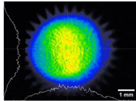
(rms) over 2 hours. The output beam profile with a diameter of 2.3 mm at the intensity point, 1/e2, is obtained with a good Gaussian profile. The stably amplified pulses are sent to a 2-pass main amplifier after expanding the beam diameter to 4 mm at the intensity point, 1/e2. A serrated aperture with a diameter of 5 mm is placed after the beam expander to avoid Fresnel diffraction.
The pulses are amplified to 200 mJ with the main amplifier with a stability of better than 0.2 % (rms) over 2 hours. The beam
Fig. 1. Schematic setup of the optically synchronized
pump laser. Fig. 3. Beam profile at 532 nm.
Fig. 2. Dependence of the center wavelength on time (a) with and (b) without the feedback control system.
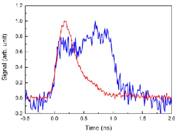
profile on the serrated aperture is relayed to an LBO crystal to obtain a high efficiency of frequency doubling. The frequency doubled (532 nm) pulse energy is 130 mJ with a stability of 0.6 % over 2 hours. Figure 3 shows the 532 nm beam profile in the LBO crystal. The triangle shape surrounding the profile is the shadow of the serrated aperture. Thecenter part on the profile at 532 nm is slightly stronger in the vertical direction. The pulse duration is measured by a 30 GHz oscilloscope and a biplanar phototube with the rise time of 60 ps. The pulse duration at the output of the fiber system is ~1 ns (FWHM), which corresponds to the specification of the FBG. However, the pulse duration becomes shorter after frequency doubling, as shown in Fig. 4. We consider that much of the pulse shortening is due to the waveform
distortion behavior of high gain amplification in the regenerative amplifier. After frequency doubling, the pulse duration of 330 ps (FWHM) is obtained at 532 nm. Further improvement of the pulse duration is needed to fully meet the J-KAREN-P system requirement.
Acknowledgments
The author thanks KIRIYAMA Hiromitsu, KISHIMOTO Maki, MORI Michiaki, KONDO Kotaro, KANDO Masaki and KONDO Kiminori for their sincere contributions.
References
1. H. Kiriyama, A. S. Pirozhkov, M. Nishiuchi, Y. Fukuda, K.
Ogura, A. Sagisaka, Y. Miyasaka, M. Mori, H. Sakaki, N. P.
Dover, K. Kondo, J. K. Koga, T. Z. Esirkepov, M. Kando, and K. Kondo, “High-contrast high-intensity repetitive petawatt laser,” Optics Letters 43(11), 2595-2598 (2018).
2. C. Y. Teisset, N. Ishii, T. Fuji, T. Metzger, S. Köhler, R.
Holzwarth, A. Baltuška, A. M. Zheltikov, and F. Krausz,
“Soliton-based pump-seed synchronization for few-cycle OPCPA,” Optics Express 13(17), 6550-6557 (2005).
3. A. Vaupel, N. Bodnar, B. Webb, L. Shah, and M.
Richardson, “Concepts, performance review, and prospects of table-top, few-cycle optical parametric chirped-pulse amplification,” Optical Engineering 53(5), 051507 (2014).
4. N. Ishii, C. Y. Teisset, S. Köhler, E. E. Serebryannikov, T.
Fuji, T. Metzger, F. Krausz, A. Baltuška, and A. M.
Zheltikov, “Widely tunable soliton frequency shifting of few-cycle laser pulses,” Phys. Rev. E 74, 036617 (2006).
Fig. 4. Measured pulse duration (blue) before regenerative amplifier and (red) after frequency doubling.
Variation in electron emission time in weakly nonlinear laser wakefield acceleration
Kai Huang
High Intensity Laser Science Group, Department of Advanced Photon Research
Laser wakefield acceleration (LWFA) [1] is one of the most intensively studied fields in high energy density science (HEDS) because of the inherent high acceleration gradient and ultrashort acceleration structure. The secondary radiation sources [2] from LWFA possess the temporal characteristics of the accelerated electrons and are considered to be useful in the application of ultrafast pump-probe studies. The resolution of a pump-probe study is determined by the duration and jitter of the probe pulse.
The single bunch duration of LWFA has been demonstrated to be at femtosecond (fs) level [3], which is consistent with the micrometer-scale wave bucket. For the aspect of timing jitter, it is assumed that the electrons are to be injected into the first bucket of the wakewave in the bubble regime [4]. Thus, they are always considered to be “jitter-free”. However, up to now, the timing information of laser wakefield accelerated electrons have not been real-time monitored. For theoretic concern, since laser wakewave is composed of a sequence of buckets, the possibility of electrons being injected into lateral buckets cannot be ignored.
This issue has been paid little attention experimentally.
For the timing monitoring of electron beams, electro-optic (EO) sampling techniques have been widely used in conventional accelerators [5]. When an electron bunch passes by an EO crystal, the coulomb field residing in THz range acts as a DC bias. A probe laser propagating through the crystal will undergo Pockels effect, causing polarization rotation that records the electron temporal profile. This technique has the advantages of non- destructive and single-shot detection. By setting an angle between the propagation direction of the probe laser with the electron beam path, the electron longitudinal information can be transversely encoded to the laser profile. This is known as the
“electro-optic (EO) spatial decoding technique”.
Fig. 1: EO spatial decoding model. The wavefront of the Coulomb field has a spherical shape with the center at the exit of plasma.
In a previous study, we introduced EO spatial decoding
technique to the LWFA study and discussed the methodology in detail [6]. We found that when placing the crystal very close to the plasma source, the wave-front of the Coulomb field had a spherical shape instead of the perpendicular plane wave model that was previously widely used. For such a special case, we derived a modified temporal mapping relationship: 𝑐Δ𝜏 = (1 + sin 𝜃𝑆/ sin 𝜃𝑃) ∙ tan 𝜃𝑃Δ𝜉, where Δ𝜉 and Δ𝜏 represent the observed displacement on the CCD and the corresponding time difference, respectively. 𝜃𝑆 and 𝜃𝑃 are the incident angles of the Coulomb field and probe laser on the EO crystal surface, as illustrated in Fig. 1.
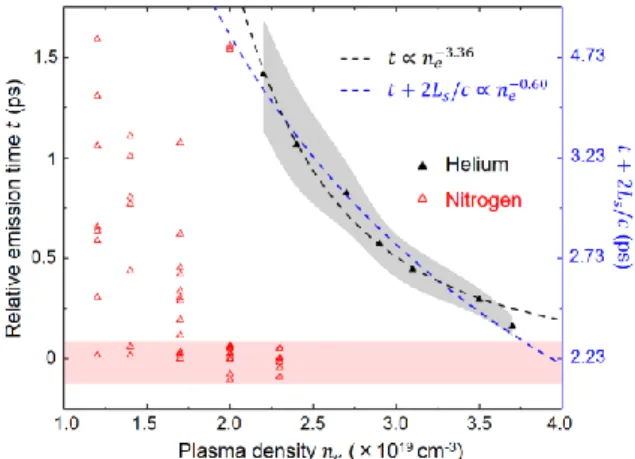
In this report, we present the observation of the plasma density dependent electron emission time variation by using the EO spatial decoding technique. The emission times of the electrons tended to be earlier with higher plasma densities, corresponding to a closer injection position relative to the drive laser pulse. The timing trend fitted well with a density down-ramp injection model. Our study suggests that for weakly nonlinear laser wakefield acceleration, jitter issues should not be ignored.
Fig. 2: Single shot EO signals vs. densities. The cases with plasma densities of {2.2, 2.4, 2.7, 2.9, 3.1, 3.5, 3.7}
× 1019 cm-3 are listed from left to right. Signals were generated from pure He gas. Multi-bunch structures were observed frequently at slightly higher plasma densities.
The experiment was performed with the JLITE-X laser system at the Kansai Photon Science Institute (KPSI), National Institutes for Quantum and Radiological Science and Technology (QST), Kyoto, Japan. In the experiment, the laser output is 4 TW with a pulse duration of 40 fs. The laser intensity on target was I
= 7 × 10¹⁷ W/cm2, corresponding to a normalized vector potential a0 ∼ 0.57, where a0 ~ 8.6 × 10⁻¹⁰ λ0 [μm] I1/2 [W/cm2]. A 3 mm conical nozzle was used for electron generation. The crystal we used was a 50 μm thick GaP crystal placed at a position (𝐿, 𝑦0) = (2.2 mm, 1.5 mm) downstream of the exit of the target, see Fig.
1. The probe incident angle on the crystal surface was set to be 𝜃𝑃= 44°.
A list of single-shot EO signals from pure helium (He) gas is shown in Fig. 2. With a moderate laser power of 4 TW, the laser wakefield acceleration worked in a weakly nonlinear mode. At higher plasma densities, the electron beams had earlier emission times. The signals had differences of nearly 1 picosecond (ps) for cases between the lowest and highest plasma density. Since the observed EO signal represented the relative timing of when the electron exited the plasma, the emission timing variation suggests that the injection position relative to the drive laser pulse varied with plasma densities. Since the detection was conductible in real-time, temporal multi-bunch structures were observed frequently during the experiment with much less efforts compared to previous literatures [7, 8].
Fig. 3: Discussion of the density dependent emission time variation. The centers of the EO signals from He are illustrated by black solid triangles. The grey shadow in the figure denotes the standard deviation of the relative emission time at each density. The black and blue dashed curves are allometric fittings between {𝑡, 𝑛𝑒} and {𝑡 + 𝐿𝑠, 𝑛𝑒}, where 𝐿𝑠= 484 𝜇𝑚 is the measured plasma scale length of the density down ramp at the exit of the gas nozzle. The red triangles are the scattering plots of the peak of the signals from N2 for background plasma densities of {1.2, 1.4, 1.7, 2.0, 2.3} × 1019 cm−3. The signals in the red zone were taken as samples for relative “zero” timing determination.
To search for the physics behind the observed phenomena, we conducted statistics of 20 consecutive shots at each plasma density for pure He gas. The statistics and analysis are shown in Fig. 3. In the self-injection regime, the electron timing fluctuation decreased from 275 fs to 48 fs when increasing the density, as denoted by the black shadow. It suggested that wave breaking was forced to occur at higher plasma densities. We considered two candidate mechanisms [9, 10] which could be responsible for the observed emission time trend: (1) For the transverse wave breaking mechanism, the wave breaking timing relative to the drive laser has a relation with the density as: 𝑡 ∝ 𝑛𝑒−5/6. However, a direct fitting between 𝑡 and 𝑛𝑒 showed 𝑡 ∝ 𝑛𝑒−3.36 (see black dashed line in Fig. 3), which was far from the transverse wave breaking model. (2) For the density down-ramp injection mechanism, the relative injection timing is related with the density as: 𝑡 + 2𝐿𝑠/𝑐 ∝ 𝑛𝑒−2/3, which fitted well with the
experimental data, as illustrated by blue dashed line (with index of -0.60) in Fig. 3. The analysis showed that the density down- ramp might be responsible for the injection of the majority of electrons and the observed timing trend in our experiment [11].
The relative zero timing was determined by the using the nitrogen (N2) gas target when ionization injection occurred.
Simulations demonstrated that high energy electrons were injected into the first bucket at a background plasma density of 2.0 × 1019 cm−3 for the laser parameters used in the experiment [11]. Additionally, the experimental results of N2 showed different timing behavior compared to that of He. At each plasma density, there were signals appearing near the “zero” timing. At plasma densities of < 2×1019 cm−3, the EO signals covered a large range of timings. At 2.0×1019 cm−3, except for two shots with very late timings, the others were constrained in a region near the zero timing. At 2.3×1019 cm−3, no signals were observed with late timings. Based on both experiments and simulations, we take the mean timing value in the red zone in Fig. 3 as the relative zero emission time.
In summary, by introducing the EO spatial decoding technique to the experimental research of LWFA, we observed the plasma density dependent electron emission time variation in the weakly nonlinear condition. Measurements indicated that, in some occasions of LWFA, the electrons were not necessarily
“jitter-free”. For application concerns, controlled injection mechanisms should be used to generate temporally stable electron bunches. The detection method in this report will be optimized for single-shot detailed measurement of the electron temporal profile and the investigation of the physics in the injection and acceleration processes.
Acknowledgments
The author acknowledges Prof. A. Zigler, Prof. P. Bolton, and Dr.
A. Pirozhkov for fruitful discussions, and Prof. Hosokai and Dr.
Sano for their encouragement. M. Kando conceived the research.
H. Kotaki, M. Mori, Y. Hayashi, N. Nakanii, and M. Kando joined the experiment. T. Esirkepov, J. K. Koga, and S. V. Bulanov provided the theoretical supports. This work was funded by the ImPACT Program of the Council for Science, Technology and Innovation (Cabinet Office, Government of Japan) and the JST- Mirai Program Grant No. JPMJMI17A1, Japan.
References
1. T. Tajima and J. M. Dawson, Phys. Rev. Lett. 43, 267 (1979).
2. K. Huang et al., Sci. Rep. 6, 27633 (2016).
3. O. Lundh et al., Nat. Phys. 7, 219 (2011).
4. W. Lu et al., Phys. Rev. Lett. 96, 165002 (2006).
5. B. Steffen et al., Phys. Rev. Accel. Beams 12, 032802 (2009).
6. K. Huang et al., Sci. Rep. 8, 2938 (2018).
7. M. Heigoldt et al., Phys. Rev. Accel. Beams 18, 121302 (2015).
8. J. van. Tilborg et al., Phys. Rev. Lett. 96, 014801 (2006).
9. S. V. Bulanov et al., Phys. Rev. Lett. 78, 4205 (1997).
10. S. V. Bulanov et al., Phys. Rev. E 58, R5257 (1998).
11. K. Huang et al., Phys. Rev. Accel. Beams 22, 121301 (2019) (Editors’ Suggestion).