Part 1, No. 4A, April 2000
°c2000 The Japan Society of Applied Physics
Phase Sensitive Pump-Probe Spectroscopy Using a Michelson-Type Interferometer
Takao FUJI∗1, Takuya YODA, Toshiaki HATTORIand Hiroki NAKATSUKA∗2 Institute of Applied Physics, University of Tsukuba, Tsukuba, Ibaraki 305-8573, Japan
(Received September 27, 1999; accepted for publication February 2, 2000)
Time-resolved phase sensitive pump-probe spectroscopy using a Michelson-type interferometer has been carried out. In this experiment, we obtain information on the time-resolved amplitude and phase of probe pulses by measuring cross-correlations between probe pulses and reference pulses. This method was demonstrated in an experiment on dye molecules, hexamethylin- dotricarbocyanine iodide, in ethylene glycol at room temperature. The experimental results indicated the time evolution of the phase and the increase in peak velocity of the probe pulse. These phenomena can be explained by phase velocity change and group velocity change due to the pump pulse. A simulation based on a two-level Bloch model for the dye molecules reproduced the experimental results quite well.
KEYWORDS: ultrafast phenomenon, phase sensitive spectroscopy, pump-probe spectroscopy, Michelson-type interferometer, ultrashort pulse propagation, nonlinear optics, induced phase modulation
∗1Present address: Department of Physics, Faculty of Science, University of Tokyo, 7-3-1, Hongo, Bunkyo, Tokyo 113-0033, Japan. E-mail address:
∗2E-mail address: [email protected]
1738
1. Introduction
Owing to the recent development of femtosecond lasers, ul- trafast spectroscopy has become more feasible, and many re- searchers have employed pump-probe spectroscopy to inves- tigate femtosecond dynamics in various materials. In conven- tional pump-probe experiments, the change of the integrated probe-pulse energy induced by the pump pulse is measured, but we are not capable of observing the phase of the probe pulse.
In order to observe the time evolution of the phase of the probe pulse, interferometric pump-probe techniques have been developed by many researchers.1–6) Recently, a novel method of observing the time evolution of the amplitude and the phase of the probe pulse was carried out by Tokunaga et al.7–9)They measured the time dependent third order suscep- tibility, and emphasized that phase measurement is crucial in the nonlinear regime because the Kramers-Kronig relation of- ten fails to connect the real and imaginary parts of the suscep- tibility.
On the other hand, we investigated the linear propagation of light in various materials by using a white-light Michel- son interferometer.10–13)The cross-correlation interferograms between the incident light and the transmitted light through samples were measured, and we were able to obtain infor- mation on the time evolution of the amplitude and phase of the ultrashort pulses with high accuracy using this technique.
The light source used in the measurement was a low-power in- candescent halogen lamp; therefore, the light propagation ob- served was in the linear regime where the Kramers-Kronig re- lation holds. In the linear regime, if the waveform of the input pulse is the autocorrelation of the incident white light, then the waveform of the output pulse is the cross-correlation be- tween the incident white light and its transmitted light through the sample.12)
In the present paper, we report the application of the Michelson interferometer to time-resolved phase sensitive pump-probe spectroscopy. In this experiment, we obtained the cross-correlation between the probe pulses which were de- formed by the pump pulses and the reference pulses. The am-
plitude and the phase of the cross-correlations reflect the time evolution of the amplitude and the phase of the probe pulse even in the nonlinear regime although convolution effects are involved. The purpose of this experiment is to observe the de- formation of the probe pulse in the time-domain which cannot be predicted by conventional pump-probe spectroscopy.
2. Experimental Setup
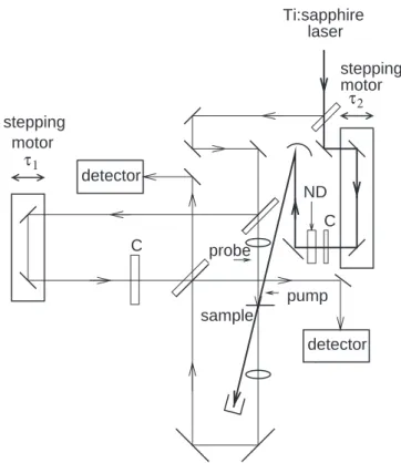
The schematic diagram of the experimental setup is shown in Fig. 1. The system is based on the white-light Michel- son interferometer developed by our group.10–13) The light source was a system composed of a Ti:Sapphire oscilla- tor (Tsunami, Spectra-Physics) and a regenerative amplifier (Spitfire, Spectra-Physics). The pulse width, the wavelength, and the repetition rate were 110 fs, 800 nm, and 1 kHz, re- spectively. The output beam of the light source was first split into two beams by a glass plate. The strong beam was used
pump τ2 τ1
Ti:sapphire laser
sample
detector detector
motor stepping
motor stepping
C probe
C
ND
Fig. 1. Schematic diagram of the experimental setup. C and ND are a glass compensator and a variable neutral density filter, respectively.
the oscillations in the interferograms in Fig. 3 because they were much faster than the envelope variations. Therefore, we separated the amplitude and the phase of the interferograms.
as the pump pulse, and the weak one was introduced into a Michelson interferometer and was again split into two arms.
The pulse in one arm of the Michelson interferometer, or the probe pulse, was overlapped onto the pump pulse on the sam- ple. The sample was a jet of an ethylene glycol solution of an
3. Results and Discussion
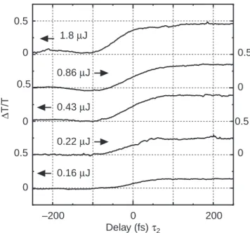
Before measuring the interferogram between the probe pulse and the reference pulse, we blocked the reference pulse, and measured the time-integrated energy of the probe pulse by scanning the delay time τ2. Figure 2 shows1T/T , or the transmission change of the probe pulse vsτ2, the delay time of the probe pulse to the pump pulse, at different pump pulse energies, where absorption saturation is shown. The de- cay of the transmission cannot be seen in this time scale be- cause the excited state population of this sample decays with a time constant of several nanoseconds. When the energy of the pump pulse was lower than 0.8µJ, the transmission change induced by the pump pulse was almost proportional to the energy of the pump pulse. However, when the energy of the pump pulse became larger than 0.8µJ, the transmis- sion change was saturated. If complete saturation occurred in a simple two-level system, the transmission would be 100%.
However, on the contrary, the transmission saturated at about 70%. This is because there is absorption from the excited state, S1, to still higher states, Sn, in the dye molecules.
Next, we measured the cross-correlation between the probe pulse and the reference pulse by scanning the delay timeτ1
while fixing the delay time τ2. Figure 3 shows the cross- correlations for different delay timesτ2. The energy of the pump pulse was set to 0.86µJ. It is quite difficult to see IR dye, 1,10,3,3,30,30-hexamethylindotricarbocyanine iodide (HITCI). The energy of the probe pulse was set to 5 nJ, but the energy of the pump pulse could be changed using a vari- able neutral density filter. The spot sizes of the pump pulse and the probe pulse were about 100µm. The angle between the probe beam and the pump beam was about 10◦. The probe pulse transmitted through the sample was overlapped onto the reference pulse, which was in the other arm of the interfer- ometer. In order to make the probe pulse on the sample close to a transform-limited pulse, we adjusted the compressor in the regenerative amplifier. Moreover, we put glass compen- sators in the paths of the reference pulse and the pump pulse in order to balance the dispersion of all three pulses. The delay time between the probe pulse and the reference pulse, τ1, and that between the probe pulse and the pump pulse,τ2, were changed by translation stages driven by stepping mo- tors. We measured the cross-correlation between the probe pulse and the reference pulse by scanning the delay timeτ1
while the delay time τ2 was fixed. If the phase of only the probe pulse shifts due to the pump pulse, the fringe of the cross-correlation will shift. This is why we can observe the phase change of the probe pulse due to the pump pulse us- ing this technique. As shown in Fig. 1, the two output beams from the interferometer were detected by two p-i-n photodi- odes simultaneously, and we took the difference between the two signals in order to raise the signal-to-noise ratio of the measurements. The differential signal was fed into a boxcar integrator. A beam from a He–Ne laser was also incident on the Michelson interferometer, and its interferogram was si- multaneously monitored for path-length calibration.
–200 0 200
Delay (fs)τ2
∆T/T
0 0 0
0.5 0
0.5
0.5 0
0.5 0.5
1.8µJ
0.86µJ 0.43µJ
0.22µJ 0.16µJ
Fig. 2. Time-integrated energy of the probe pulse vs the delay timeτ1of the probe pulse to the pump pulse. The energy of the pump pulse is indi- cated in the figure.
–500 0 500
–20 0 20
Delay (fs) τ1
InterferenceSignal(arb.units)
without pump
τ2= –770 fs τ2= –210 fs τ2= –100 fs τ2= 0 fs τ2= 70 fs τ2= 900 fs
Fig. 3. Cross-correlation interferograms between the probe pulse and the reference pulse for different delay timesτ2. The cross-correlation without pumping is shown in the inset.
to decrease; therefore, the phase of the probe pulse advances with time. This is the reason for the advance in phase of the probe pulse when the delay time τ2 is larger than−200 fs, and the steep advance in phase whenτ2 is around−100 fs.
The steep advance in phase with time is equivalent to the blue shift of the center frequency of the probe pulse. This phenomenon, called induced phase modulation, was also de- tected in the case of the spectral interferometric method.7–9) In the present, experiment we observed this phenomenon in the time-domain.
Accordingly, the peak shift of the probe pulse also seems to be due to the decrease in the refractive index. If1n is the refractive index change induced by the pump pulse, the peak shift1τ of the probe pulse can be expressed as follows:
1τ =1nl/c, (1)
where l is the thickness of the sample. Even if the satura- tion occurred completely, and the absorption spectrum be- came completely zero, the peak shift of the probe pulse due to the decrease in the refractive index would be about 1 fs. How- ever, the observed magnitude of the peak shift of the probe pulse was at least 10 fs. Therefore, it is impossible to explain the peak shift by considering only the decrease in the refrac- tive index.
Consequently, we have to take into account the effect of group velocity. The group velocity is expressed as follows:
vg=dω
dk (2)
= 1
d
dω(ωnl/c)
, (3)
where k is the wave number. In this equation, the group velocity is approximately inversely proportional to the gra- when the pump pulse was off. In Fig. 4 we can see that the
phase increased steeply at aroundτ1=0 when the delay time τ2was set to about−100 fs, and that the peaks of the cross- correlations shifted earlier by about 10 fs when the delay time τ2 was positive, τ2 > 0. Based on these experimental re- sults, we can say that the phase of the probe pulse increased steeply at aroundτ1 = 0 when the delay timeτ2 was set to about−100 fs, and that the peaks of the probe pulses shifted earlier by about 10 fs when the delay time τ2 was positive.
These phenomena cannot be detected by conventional time- integrated pump-probe spectroscopy.
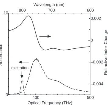
Here, we discuss the phase change and the peak shift of the probe pulse. Figure 5 shows the absorption spectrum of the sample, which was measured by a grating monochro- mater, and the refractive index spectrum, which was obtained by a Kramers-Kronig analysis of the absorption spectrum.
The excitation pulse spectrum is also shown in this figure.
When the pump pulse is incident on the sample, the absorp- tion decreases due to the increase of the excited-state pop- ulation. Based on the Kramers-Kronig relation, we can say that the refractive index in the spectral region of the probe pulse decreases when the absorption decreases. During the pump pulse, the absorption and the refractive index continue Figure 4 shows the amplitude and the phase of the interfer- ograms. The phases were subtracted by a line which had the gradient of the center frequency of the cross-correlation
–500 0 500
Amplitude (arb. units)
Delay (fs)
Phase (rad.)
without pump
τ2= –770 fs
τ2= –210 fs τ2= –100 fs
τ2= 0 fs τ2= 70 fs
τ2= 900 fs π
τ1 phase
amplitude
Fig. 4. Cross-correlation interferograms between the probe pulse and the reference pulse for different delay timesτ2. Solid curves are the ampli- tudes, and dashed curves are the phases.
Optical Frequency (THz) Wavelength (nm)
Absorbance
excitation
Refractive Index Change
400 500
0
10 800 700 600
–0.004 –0.002 0 0.002
Fig. 5. Absorption spectrum (dashed curve) and refractive index spectrum (solid curve) of HITCI in ethylene glycol. The absorption spectrum was measured using a grating spectrometer, and the refractive index spectrum was obtained from the absorption spectrum using the Kramer-Kronig rela- tion. The refractive index in this figure is the difference from that of the solvent, ethylene glycol. The dotted curve is the spectrum of the excitation pulse.
where1dis the detuning between the peak frequency of ab- sorption and the center frequency of the pump pulse, and 1ωis the width of the inhomogeneous broadening. We set 1ω = 55×1012rad/s, which was obtained in ref. 14 and 1d =25 THz. The homogeneous broadening, 1/T2, was set to 17.5 THz which was calculated to fit the main peak of the absorption spectrum measured with a monochromater.
The density matrixρ(ˆ x,t)and the electric field of the pump pulse E(x,t) were numerically calculated using the above conditions. Using the obtained ρ(ˆ x,t), the propagation of the weak probe pulse was calculated in the linear approxima- tion. Finally, the cross-correlation between the transmitted probe pulse and the reference pulse was calculated. Figure 6 shows the simulated results for the cross-correlation between the transmitted probe pulse and the reference pulse. The re- sults of the simulation reproduce the key features of the exper- iment. Atτ2= −100 fs, the phase advances steeply at around
whereω0andω1are the eigen frequencies of the ground state and the excited state, respectively, E(x,t)is the electric field of the pump pulse, and ω is its center frequency, N is the density of the molecules, andhidenotes the stochastic average over the inhomogeneous broadening. The magnitude of the electric dipole moment, p, was set to 3.6×10⁻²⁹m·C from the lifetime of the excited state,∼10 ns. We assumed a Gaussian pulse shape:
lation. Therefore, we can see that the group velocity becomes larger when the absorption decreases, or absorption saturation occurs. When the group velocity changes fromvg tovg0, the peak shift1τ should become as follows:
1τ = l vg0
− l vg
(4)
=l µdk0
dω− dk dω
¶
(5)
=
· 1n+
µdn0 dω − dn
dω
¶ ω
¸
l/c. (6) From this equation, we see that when complete saturation oc- curs, the peak shift is 24 fs. Therefore, we can say that the decrease in the gradient of the refractive index to the optical frequency due to saturation is the reason for the increase in the peak velocity of the probe pulse when the delay timeτ2is positive.
The peak shift can also be observed by the gate method with nonlinear effect, for example Optical Kerr Gate, or the up-conversion method. The advantage of our method is that the signal-to-noise ratio is much better than in the case of these methods because we use the linear interference effect.
4. Simulation by a Two-Level Bloch Model
For a more detailed quantitative discussion, we simulated the propagation of the probe pulse in the sample. In this sim- ulation, the sample was modeled as a two-level system which is broadened inhomogeneously. At first the propagation of the strong pump pulse in the sample was calculated. We ex- pressed the density matrixρ(ˆ x,t)as follows:
ˆ
ρ(x,t)= |0iρ00(x,t)h0| + |0iρ01(x,t)h1|
+ |1iρ10(x,t)h0| + |1iρ11(x,t)h1|, (7) where|0i and|1iare the ground state and the excited state, respectively. The density matrix obeys the following simulta- neous equations,
˙ˆ
ρ(x,t)= i
¯ h
hHˆ0− ˆp E(x,t),ρ(ˆ x,t)i
, (8)
P(x,t)=N ˆ pρ(ˆ x,t)®
, (9)
∂
∂xE(x,t)= iω
2²0cP(x,t), (10) where
Hˆ0= |0i¯hω0h0| + |1i¯hω1h1|, (11) ˆ
p= |0iph1| + |1iph0|, (12) dient of the refractive index to optical frequency. On the other hand, the gradient of the refractive index to optical fre- quency in this spectral regime decreases when the absorption decreases. This is a consequence of the Kramers-Kronig re-
–500 0 500
without pump
τ2= –770 fs τ2= –210 fs τ2= –100 fs τ2= 0 fs τ2= 70 fs τ2= 900 fs
π
Delay (fs)τ1
Amplitude (arb. units) Phase (rad.)
amplitude phase
Fig. 6. Simulated cross-correlation interferograms between the probe pulse and the reference pulse for different delay timesτ2. Solid curves show the amplitude, dashed curves show the phase, and dotted curves show the time evolutions of the excited state population due to the pump pulse.
was obtained from the energy of the pump pulse, 0.86µJ and the beam size. The inhomogeneous broadening function G(1)was expressed as follows,
with1t =110 fs for the input pulse. The pulse area of the pump pulse which is proportional to A was set to 23 rad which E(x,t)= A exp[−2 ln 2t2/1t2]exp(−iωt)+c.c., (13)
G(1)=exp[−1/2(1−1d)2/1ω2], (14)
τ1 =0, and atτ2 >0 the peaks of the probe pulses shifted forward by about 10 fs. This fact supports the discussion in
§3. The dotted lines in Fig. 6 are simulated time evolutions of the excited-state population due to the pump pulse. We can clearly see that the phase varies with the population. This in- dicates that the most important factor for the phase variation and the peak shift of the probe pulse is the change of the re- fractive index spectrum induced by the pump pulse. This is because the spectrum of the light pulses in the present experi- ment is on the longer wavelength edge of the absorption band of the sample. In such a case, the effect of the refractive index is more important than absorption for pulse deformation.
In the above simulation, the absorption from the excited state S1of the dye molecule to still higher excited states Snis not considered. The wavelength of the probe pulse is well within the absorption band between the S1 and Sn states.
Therefore, the effect of this absorption on the refractive in- dex change is considered to be small and thus the effect on the probe-pulse deformation is considered to be negligible.
Moreover, the inclusion of the coherent coupling effect be- tween the pump pulse and the probe pulse made no significant difference to the simulated results.
5. Conclusions
Phase sensitive pump-probe spectroscopy on a dye solution using a Michelson-type interferometer was carried out. The time-resolved amplitude and phase of the cross-correlations between the probe pulses and the reference pulses were mea- sured by this technique, and the time evolution of phase and the peak shift of the probe pulse were clearly found by the cross-correlations. In order to explain the results, we sim- ulated the pulse propagation using a two-level Bloch model
with inhomogeneous broadening. The simulated results re- produced the key features of the experiment. On the basis of the simulation, the main factor of the probe-pulse deforma- tion is considered to be the refractive index change induced by the pump pulse.
Acknowledgements
This work was supported in part by the Grant-in-Aid for Scientific Research (B) of the Ministry of Education, Science, Sports and Culture.
1) J.-M. Halbout and C. L. Tang: Appl. Phys. Lett. 40 (1982) 765.
2) Y. Li, G. Eichman and R. R. Alfano: Appl. Opt. 25 (1986) 209.
3) D. Cotter, C. N. Ironside, B. J. Ainslie and H. P. Girdlestone: Opt. Lett.
14 (1989) 317.
4) N. Finlayson, W. C. Banyai, C. T. Seaton, G. I. Stegeman, M. O’Neill, T. J. Cullen and C. N. Ironside: J. Opt. Soc. Am. B 6 (1989) 675.
5) M. J. LaGasse, K. K. Anderson, H. A. Haus and J. G. Fujimoto: Appl.
Phys. Lett. 54 (1989) 2068.
6) K. Minoshima, M. Taiji and T. Kobayashi: Opt. Lett. 16 (1991) 1683.
7) E. Tokunaga, A. Terasaki and T. Kobayashi: J. Opt. Soc. Am. B 12 (1995) 753.
8) E. Tokunaga, A. Terasaki and T. Kobayashi: J. Opt. Soc. Am. B 13 (1996) 496.
9) E. Tokunaga, A. Terasaki, V. S. Valencia, T. Wada, H. Sasabe and T.
Kobayashi: Appl. Phys. B 63 (1996) 255.
10) T. Hattori, N. Tsurumachi, S. Kawato and H. Nakatsuka: Phys. Rev. B 50 (1994) 4220.
11) N. Tsurumachi, T. Fuji, S. Kawato, T. Hattori and H. Nakatsuka: Opt.
Lett. 19 (1994) 1867.
12) T. Fuji, M. Miyata, S. Kawato, T. Hattori and H. Nakatsuka: J. Opt. Soc.
Am. B 14 (1997) 1074.
13) T. Fuji, M. Arakawa, T. Hattori and H. Nakatsuka: Rev. Sci. Instrum.
69 (1998) 2854.
14) M. S. Pshenichnikov, K. Duppen and D. A. Wiersma: Phys. Rev. Lett.
74 (1995) 674.