Architectural Institute of Japan
NII-Electronic Library Service
ArchitecturalInstitute of Japan
tst
g}
UDC:624.012.46
JoumaL
ofStructuTal
andConstructibn
Engineering
(Transactions
ofAIJ)
No,365,
July,
1986
H"eN\AptinthkcaXvaEM
eg
365
g・meip
61
f7fi
EXPERIMENTAL
STUDY
ON
INTERNAL
CRACKING
OF
PARTIALLY
PRESTRESSED
CONCRETE
FLEXURAL
MEMBERS
Part
2
:
Internal
ctacking
characteristics
by
KAZUO
SUZUKI',
YOSHITERU
OHNO"
and
SOMCHAI
SRISOMPONG"'",
Members
ofA.
I.
J.
1.
introduction
The
authorshave
previously
reported anewlydeyeloped
investigation
technique
for
internal
cracking of concreteflexural
membersin
whichink
andlor
epoxy
resin are used asinjecting
materialsin
Part
1
[
1
]
,
The
technique
wastermed
"doubleinjection
technique".
The
results of examinationindicated
that
ink
and resin canbe
injected
together
in
the
same・specimento
obtainnot
only
internal
cracking
patterns
but
also sizes ofthe
cracksdirectly.
In
this
paper,
results ofinvestigation
on
internal
cracking of reinforced concrete(RC),
prestressed
concrete(PC)
andpartially
prestressed
con'crete(PPC)
beams
by
means of"double
injection
technique"
are reperted,The
test
variabLes weretype
of member,types
of
reinforcing
and
prestressing
steels and size of aggregate.Internal
crackingcharacteristics,
for
instances,
interior
cracking
pattern,
sizes
and
inteTior
conditions ofprimary
cracks, conditions of cracksin
grout
andthe
separation
phenomenon
between
the
reinforcing steel and concrete etc. , arediscussed.
2.
Test
Program
2.1
Test
Specimens
andMaterials
The
test
program
outlinedin
Table
1
wassubdivided
into
three
series.Test
beams
consisted oftotally
thirteen
f-i2-1
ti2-
Fi2--1
115
Rc
holeppc
PC
Fig.1
Sectional
details
of testbeams
1
(unit:cm)
ReinforcingPrestressingsteelMeximum
iBeammark
steelTypeL,
Type
AoP2{kgf!cm)aggregatesize(mm)
1-8-H・RC-1PC-1Dt9-
-Smoethbar .2000
le10
almPPC.1
D19
Smoothbar1060
to
LFpt1
PPC-2
D19
Smoothbar
1060
s
is?pC-3
pt19
Smoothbar
133010
'aPPC-4
D19
Smeothbar
1310
10
8PPC-5
D19
Smeethbar
1310
20
i
PPC-R
D19
Smoothbar
950
10 oPPC-DD19
DeformedBar920
10
8
?pc-s
'
D19
Strand
930
10
'cppc-s.D19
Strand.
la2o
10
Uuapc-s-
Strand
270010
pc-s-
.
Strand
2700
leFig.2
Details
fo
deformed
bar
D19
{unit:mrn)
*
Prefessor
ofOsaka
Universitv,
DT,Eng.
i*Research
Associate
ofOsaka
University
S*'Graduate
Student
ofOsaka
University
<Manuscript
reeeivedSeptember
9, 19g5)-9-Architectural Institute of Japan
NII-Electronic Library Service
ArchitecturalInstitute of Japan
in
the
test
Beams
wereunloaded,
splitted and cutby
the
sameprocedure
asdescribed
in
Part
1
[
1
].
The
diagram
of cuttingis
shownin
Fig.
3,
After
splitting, sheath contained withgrout
anclprestressing
steel was removedfrom
the
concreteand
cutlongitudinally
into
two
equalparts
with adiamond
saw.Then
prestressing
steel
was removedfrom
the
grout
to
observethe
conditions
in
the
recess.part.
Inspection
of cracks weredone
with
40
times
magnification
micrascopein
various spots(see
During
the
test,
changes
in
surface ciack widthsin
variouscutting
etc.
, were measuredin
6rder
to
checkthe
cthe
same way asin
tests
described
in
Part1.
3.
Test
Results
and
Considerations
3.1
Internal
Cracking
Pattern
General
patterns
ofinternal
cracking after removal o5.
The
hatched
areas representareas
of separationbetween'reinf
prestressing
steel
and
grout.
Fig,
4
showsinternal
crackingpattern
of
beams
in
Series
1.
explainedby
Goto
[4],
[5]
canbe
seen.RC-1
andPPC-1
were similarin
their
numbers, whereasin
constant mornent span.
The
tise
RC
andPPC
beams.
Fig.
4
also
showsthe
internal
crackingpattern
ofbeams
in
S
bar
in
beam
PPC-3
nor around sheathin
anybeam,
pieces
ofRC,
PC
and.PPC
types,
Test
variablesdgsignated
in'
Series
l,
2
and3
weretype
ofbeam,
type
of reinforcing steel and size of aggregate,and
type
ofprestressing
steel,' respectively.Beam
cross section was12
by
25cm
rectangular andthe
length
was20ocm.
The
sectionaldetails
of specimens are shownin
Fig.1.
High-early-strength
portland
ceinent, river sand and crushed stone were usedfor
concrete.Waterlcement
ratio wasO.
55.
For
grout,.
Pozzlith
No.8
ofO.
25,%
and aluminumpowdgr
ofO,
O05
%
of'cement
by
weight, were mixed with cementpaste
withwaterlcement
ratio ofO.
45.
Riyer
sand whighhas
maiimum size of5
mm andcTushed
stones with maximumsizes
of
10
and2o
mm were used as aggregatesfor
the
concrete.
The
compressive strength of concrete atthe
time
ofbeam
test
were312-370
kgflcrnl..
Those
ofgrout
in
the
first
two
seriesand
Series
3
were290-370
and410-510
kgflcm2,
respectively,Deformed
bar
D
19
and
roundbar
ip
19
were usedfor
reinforcement.Fig.
2
showsthe
details
of
reinforcing
.bars
D19.
Types
ofprestressing
steel used were smooth roundbar,
deformed
bar
and
'
'
'
seven-wire
strand
of11,
11
and11,
1
mmnominal
diarneters,
respectively.Spiral
sheath withinner
diameterof
23
mm'
was
used
The
fabrication
ofinjection
system wasthe
sameas
in
the
tests
described
in
Part
1
[
1
].
The
initial
prestressing
force
was6
tons
equally
in
PC
andPPC
beams
excepttwo
beams
withS*
mark.Seven-wire
strands weredirectly
embeddedin
concretein
these
two
beams
witheutprestressing
in
orderto
simulatepretensioned
beams.
Since
cracksin
concrete members relatedirectly
not withthe
real stress a.but
the・increment
of steei stressfrom
the
decompression
Aa.
(as
discussed
in
References
2
and3),
the
increment
of
stiess
was controlled.Internal
cracking
wasinspected
atthe
increment
of
2
OOO
kgffcm2
of steel stress.However,
in
beam
PC-S
andPC-S*,
the
target
valuefor
the
increment
had
been
exceedecl
at
crackingdue
to
the
smaller sectional area ofthe
seven-wire strand.In
the
calculation efincrement
of stress of reinforcing andprestressing
steels,
not
onlyloss
ofprestressing
force
but
alsothe
compressiveforce
in
the
reinforcing steel causedby
creepand
shrinkage of concrete weretaken
into
account2.2
Loading,
Injection
and
Inspection
・,
Beams
were set upas
simply-supported
type
and monotonouslyloaded
atthe
third
points
of60
cm
constant moment span.The
:a :a Ta
double
injection
technique
proposed
in
Partl
[1]
was appliedi
'
i
i
'
i
i
:p..
A,B1
1・
l
1ttttt
-ttttt
l
'i
laRCP.
9.
ABl
i
1
l
c.gh'
AIBI--・o--....t...i
'i
:a :a PCPPC
Fig.3
Diagiam
of cb prct c't.ijZ"Crack . Mensured point cuttmgFig.3).
sifages,
i.e/
, afteT resininjection,
unloading
aridhange
in
internal
crackingby
using contacttype
strairigauges
in
'
f
reinforcing andprestressing
steels are shownin
Figs
4,
orcing steel and concrete, sheath and concrete,andand
InteTnal
gracks
originatedfrom
lugs
ofdeformed
bar
as
There
was nointemal
crack aroundthe
sheath.Primary
cracksin
beam
beam
PC-1,
only apair
ofprimary
cracksformed
in
the
ofdeformed
reinfercing steel was very.effective
to
distribute
primary
cracksboth
in
eries
2.
Internal
crackdid
notform
aroundthe
round
The
number ofprimary
cracksin
beam
PPC-3
were much smallerArchitectural Institute of Japan
NII-Electronic Library Service
ArchitecturalInstitute of Japan
.F
toadingpoint
:MEZ:L-.
TM
iPrimary
crack
Internal
crack5'Intenor
'
ofgTout・1' H'
1N4
A-i-
'
1Separatian
Ii
area !i 1Ufl1
1'
pa1NUpt8Q'-Hblco
Steelrecess
r
1
m'4Urun1-11Y8m
1
[
d
at1Utum n1Umfl?xm
-m+UmpmrDading'pomt
F
Inter
±orofgreutt'1/'Pruna:ycrackSheathxecess/1:
'''''tttr''''
''ii''''
u
eparrationamG!
1'
'''i''''
/t'ttttt
t
ttt'''
t
''
Internalcrack
ts
'
i
・
'
1
,1,,,/,JIir':tt''
'
I
Steelrecess
w l'tt
' um 1 kge,
gg/
m'
M
: ene setof priJnarv cracks propagated from both side facesM
i dne setof primury cracks propagated from both side fapes of thgtm and did motjoin
w±th each other of the tm and did rDtjoin
with each otherFig.4
Internal
cfackingpattem
ofbeams
in
Series1
and2
Fig.5
Internal
crackingpattern
ofbearns
in
Series3
than
in
the
others.In
beam
PPC-2
of sand・cement mortar(maximum
aggregate size:
5mm),
shapes ofprimary
cracks were rather simple.Hoviever,
in
beams
PPC-4
andPPC-5
where aggregate of maximum sizes ofIO
and20
mm respectively were used,the
shapes ofprimary
cracks were consequentlydistorted
due
to
the
blockage
of
large
stone
particles.
Fig.6
(a),
{b}
and(c)
show close-up views ofprimary
cracksin
beams
PPC-2,
PPC-4
andPPC-5,
respectively.Shape
ofprimary
crack seemedto
be
dominated
by
size of aggregate,however,
the
number of cracksdid
not vary with size of aggregate,Fig.5
shows
general
crackingpattern
ofbeams
in
Series3.
Internal
cracksformation
in
this
series wasless
extensive
than
in
Series
1
and2
because
ofthe
lower
tugs
ofdeformed
bar
in
this
series.The
numbers ofprimary
cracks
in
beams
PPC-R,
PPC-D
andPPC-S
were very simiLar with one another, suggestingthat
there
was no effectof
deformity
ofprestressing
steel uponthe
formation
ofprirnary
cracks.Cracks
formation
depended
only ondeformed
'
reinforcing
bars.
Internal
crackdid
notform
around sheathin
spite oithe
deformity
of sheath suifacebecause
the
transmission
offorce
from
the
prestressing
steelthrough
grout
and sheathto
the
concrete was notgood
enough sincethe
grout
crackedin
alarge
number.Pattern
ofcracks
in
beam
PC-S
resembled
that
of
beam
PC-1
in
Series
l.
Since
deformed
bars
were not usedthe
distribution
of cracksin
beams
PC-S
andPC-S'
was
not
so
good
as
in
beams
of
PPC
type
andtherefore,
numbers of cracks were small and each crack was wide.
Architectural Institute of Japan
NII-Electronic Library Service
Architectural Institute of Japan
The
ameunt ofinternal
cracks
in
this
test
wassmaller
than
that
observedin
Goto's
wheredeformed
bars
oflarger
sizes
(D
32
andD
51)
had
been
used.This
is
because
the
height
of
lugs
ofdeformed
bar
has
influence
uponthe
formation
ofinternal
cracks as notedby
Goto&Otsuka
[5].
.
3,2
Interior
Conditions
ofPrimary
Cracks
'
The
internal
crack widths inthis
test
weredetermined
by
measurement
ef
the
widths retainedby
hardened
resin.'
'
(mm
aggregafesize
:
Fig6(a)
Condition
of aprimary
crackch
'
5rrm)
'
from
horizontal
sectionb-b
efbeam
PPC-2
Ckmcrete
side
faoe
t. '
ge
¢19
bar
`}iii
y.'.f,
recessttttS,i.:,.;.
o;'.,
p'1'q・i/t''
Crack
branch
Stone
partiele
'
Prirrury
crack
'
'
'
-t
ttt
'
.:
--
12-Fig.6(b>Condition
ofaggregatesize
:
IO
rnm)
aprimary
crackfrem
horizontal
sectionSeparatiQrJ
atea
'
bJb
ofbeam
PPC-4
Cumt
:
mm)Architectural Institute of Japan
NII-Electronic Library Service
ArchitecturalInstitute ofJapan
'
'
'
(Maxiinum
aggregate
size
:20
rnm)
Fig.6{c)
Condition
of aprimary
crackfrom
yertical section a-a ofbeam
PPC-s
(unit:
mm)The
narrowest width of crack which resin couldpenetrate
wqs approximatelyO.
OOs
mm similarlyto
that
in
Part
1
[1],
Fig.7
(a)
shows widths ofprimary
cracksand
their
changes
from
the
tension
faces
ofbeams
to
the
steelsin
the
vertical sections a-a(see
Fig.
3J
ofbeams
in
Series
1.
Large
decrease
in
widthef
primary
cracks
at
steel
surface
in
beams
RC-1
andPPC-1
was observed, whereas,in
beam
PC-1,
the
samecharacter
was not observed.Fig.
7
(b)
shows widths ofprimary
cracksin
hQrizontal
sectionsb-b
and c-c(see
Fig.3)
of
the
samebeams
shownin
Fig・7
o
RiSectinn
trb-
craelt "dthtmm)[ SeCti%C-C-.i
ii
.S,ii,.III.lili.,,:.,,.-,Sil,
.m:,---2]o
.r,i:'
oL2:ts:.ke":.Li,,i-zt]:o
Flg.
7
(a)
Widths
andinterior
condition ofprimary
Fig.
7
(b)
Widlhs
andinterior
cendition ofprirnary
cTacks atcracks at vertical section
(a-a)
ofbeams
horizontal
sectiDn(b-b
and c-e) ofbeams
RC-1,
RC-1,
PPC-1
andPC-1
PPC-1
andPC-1-13-Architectural Institute of Japan
NII-Electronic Library Service
ArchitecturalInstitute of Japan
12SEEieo-c,2
7sthl
,,it
,,・.n ls1
oSectlon
a-aSineath
stLeei
:
O.l Crdck,Fig.8
eo・Section
b-b
Crack width(mm)
O.i
O,2
O.3 D-K.g-,
O.2 O.3 O.4 Wicch
(rm)
Widths
andinterior
conoEg 24
g,,E
!4e
1-
24Sectlon
orclt
,,i,,
g.
5o'.ny 25 T--SteelV
DO.1dition
of = O..2 O.] Crack widthprimary
cTacksin
beam
O
O.l O.2 rr
"Sheath
eCrtm)PPC-3
--O.1
O.2(a),
The
decrease
in
width ofprimary
crackfrom
the
surfaceof
concrete
to
steel was observed atthe
reinforcing steellevel
(section
b-b)
asforrnerly
statedby
Got6
&
Otsuka
[5]
,Husain
&
Ferguson
[
6
]
andILIston
&
Stevens
[
7
].
Whereas,
atthe
prestressing
steellevel
(section
c-c>,
sinceinternal
crackdid
notform
around sheaththere
was no'
'
'
such
deciease.
Fig.
8
shows widths ofpTiTnary
cracksof
beam
PPC-3
reinforced
with roundbar
¢
19.
Since
internal
crackdid
notform
aroundthe
roundbar
and
sheath,the
decrease
in
width ofp[imary
cracksin
horizontal
sectionsb-b
and
c-c
could notbe
observed.Widths
of
cracks
in
this
beam
were widerthan
those
observedin
the
others,for
instance,
the
widths at steel surface were approximatelyO.
2
mm which was much widerthan
in
the
beam
reinforced withdeformed
bar
D
19.
These
characteristics
suggestthat
the,foimation
ofinternal
cracks andbranching
behavior
ofthe
primary
cracks
have
muchinfluence
to
reduce widths ofprimary
cracks asthey
propagate
to,reach
the
bar
surface.
In
this
stucly whendefermed
bar
D
19
wqsused
the
widths ofprimary
cracks atthe
bar
surface wereindependent
ofthose
atthe
beam
sideface
atthe
samelevel;
and were mostly na'rrowerthan
o.osmm.
Fig.
9
shows widths ofprimary
cracksin
beams
ofSeries
3
in
whichdifferent
types
ofprestressing
steel were used.The
decrease
in
width ofthe
primary
cracksfrom
the
concrete surfaceto
the
D
19
deformed
bar
particularly
in
the
horizontal
sections couldbe
confirmedto
exist and agreed witheach
other very well.It
is
unlikelythat
the
deformity
ofprestressing
steel surfaceinfluence
the
widths ofpripary
cracks,Cranston
&
Spiers
[
6
]
performed'test
on a' reinforced concreteprism'
subjectedto
pule
tension
iri
orderto
obse[ve/
the
internal
crackingphenomenon,
After
loading
and
unloading
they
cut
away
the
concrete
closeto
the
bar.
Then
the
'
'
specimen was
'reloaded
to
the
same strainto
reopenth'e
cracks
for
photography.
Fig,10shows
sketchfroin
the
CoNteltsuFdi[egIOO
E.
,,,:S 50gs !os:t i5 o O,1 erack whlth[mm) Section a-aFig.9
Effect
ofprest[essing
condition ef
ptlmaiy
a[aelt width [ff[n) O O,1 n r 2SEi 5pg'S. 5ogzs:.
o -SteelL o steelcrack L O.1CIack width (rm) Sectiontub type andinterior
in
beams
ofSeries3
'
o・zapm
Fjg.10
Widths
andinterier
conditien'ofa
primary
erackinvestigated-by
Cranston
&
Spiers,
Courtesy,
A,W.
Beeby
[6]
-14-Architectural Institute of Japan
NII-Electronic Library Service
ArchitecturalInstitute of Japan
photograph
(Courtesy.
A.
W,
Beeby
[
6
]
),
in
whichthe
width ofprimary
crackdecreases
from
the
concrete surfacetowards
the
steel surface andthe
crack appearsdiscontinuous.
Based
ontheir
wo;ks and some others'Beeby
gave
acomment
that
prirnary
crack
wasdiscontinuous,
In
the
authors' case, sincethe
"doubleinjection
technique"
was applied,
primary
cracks were seento
be
continuous alongthe
length,
Figs.
6
(a)N(c)
show some examplesof
primary
cracks
observed
in
sections a-a andb-b.
The
test
resultsindicated
that
the
"interiorcontinuity" of
primary
cracks
is
most
likely
to
exist.
In
case ofCranston
&
Spiers,
there
mighthave
been
parts
of narrow cracks,linking
the
wider and visible ones.And
since any erackdyeing
technique
was not employed, suchlinking
parts
could notbe
noticed.'
The
interior
¢ontinuity ofprimary
cracksdefined
in
this
test
could
lead
to
a considerationthat
primary
cracks might allowthe
corrosive atmosphereto
be
in
contact withthe
embedded
reinforcementin
due
time.
3.3
Cracks
in
Grout
Results
of observation on cracksin
grout
were also shownin
the
illustrations
ofFigs.4,
and5.
Some
were se narrowthat
resin could notpenetrate.
However,
sinceboth
ink
and resin wereinjected
together
in
the
same specimen,・the overallformation
of cracksin
grout
wasobservable.
Fig.4
showsthat
in
Series
1,
cracksin
grout
concentratedat
the
locatibn
of
primary
cracks andhave
larger
sizesin
those
vicinitiesthan
elsewherealong
the
bending
span.'
Fig.
4
also showsthat
there
were numerouscracks
in
grout
in
bearns
in
Series
2.
This
is
because
whenthe
number ofprimary
cracks
increased,
number
of
cracksin
grout
alsoincreased
andthese
cracks weredistributed
likewise
to
all overthe
span.It
is
unlikelythat
type
of reinforcing steel and size of aggregateinfluence
the
occurrence
and
pattern
of cracksin
grout.
In
beam
PPC-3
Teinforced with round reinforcingbar,
widths ofprimary
cracks and cracksin
grout
werelarge$t
arnongthe
test
beams,
At
the
Iocation
where width ofptimary
crack
on concrete surface(at
the
level
of
prestressing
steel)
was aboutO.
21
mm,that
of crackin
the
grout
was aboutO.
05
mm.In
otherbeams,
where widthsof
primary
cracks at,the samelevel
were aboutO.
1
mm,those
of cracksin
gtout
wereO.
035
rhm.Largercracks
seemedto
be
crowdedin
the
vicinities ofprimary
cracks.These
results suggestthat
there
mustbe
some relationshipsbetween
widths ofprimary
cracks andthose
of cracksin
grout
in
the
samelocation.
Fig.
5
shows
that
the
number
of cracksin
grout
was smallestin
beam
of.roundprestressing
bar,
larger
in
beam
efdeformed
bai
andlaTgest
in
the
one of seven-wire strand.The
amount
of cracksiri
grout
in
which not onlyink
but
also resin couldpenetrate,
enablingthe
crack width measurement werein
the
rates of'approximately
100,
90
and80
percent
in
beams
of roundprestressing
bar
(PPC-R),
deformed
bar
{PPC-D)
and seven wire strand(PPC-S),
respectively.And
the
average
crack
widths wereO.
023,
o.
o15
andO,
O13
mm, respectively.This
suggeststhat
the
deformity
ofprestressing
steelsurface
have
muchinfluence
uporithe
formation
of cracksin
grout.
Photo
1
shows acrackin
grout
which was aboutO.
045
mmin
width and represents atypical
feature
of
the
shape of almost straight andno
branches.
There
was nodecrease
in
widthfor
tliese
cracksfrom
sheathinner
surfaceto
the
prestressing
steel
surface.Widths
of cracksin
grout
observed
in
this
test
neverexceededO.
05
mrn.It
is
reasonablethat
the
use ofprestressing
steels of other,sizesthan
the
ones usedin
this
test
may alterthe
above mentioned value3.4
Phenomenon
ofSeparations
'
The
separations were observedin
three
areas:atthe
reinforcing steellconcrete, sheath!concrete andprestressing
steellgroutinterfaces.
iliustrations
ofFigs.4
and5
by
the
hatched
areas onthe
reinforcing steel,These
areas representthe
staining of resin seen as clear cutboundaries,
The
was considered asthe
significant area of separationin
this
study,Observecl
resultsfrom
Series
1
indicate
that
atthe
same magnitude ofAa..
interface
similarly occurredin
beams
PPC-1
andRC-l.
This
is
cracks
in
these
beams
were very similar with one another.Average
lengths
of separation at reinforcing steellconcreteinterface
in
Photq1
A
crackin
grout
enfult
length
{unit:mm)
The
extent of separation was atso shownin
sheath and
prestressing
steel recesses.staining area of resin over
that
ofink
seperation at reinforcing steellcencrete
because
the
patterns
ofinternal
cracks
andprimaTy
beams
PPC-2,
-4
and-5
ef
Series
2
wereArchitectural Institute of Japan
NII-Electronic Library Service
ArchitecturalInstitute of Japan
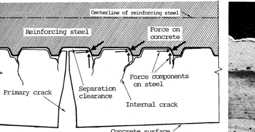
Fig.
11
Idealized
diagram
of cracks,force
components and separationbetween
concrete and Teinforcing steel
'
46.
7,
35.
2
and42,
2
mm, respectively.These
values suggestthat
sizesof
aggregatedo
notinfluence
the
phenomenon
of separation.Although
widths ofprimary
cracksin
beam
PPC-3
reinforced with roundbar
weretotaily
wider
than
those
in
beam
PPC-2
reinforcedwith
deformed
bar,
the
extents of separation were aboutthe
same.Moreover,
calculation oflateral
deformation
of reinforcingbar
showedthat
the
total
shprtening ofrbe
diameter
was approximatelyO.
O06
rnmwhen
Aale
was2
OOO
kgffcmZ.
However.
the
majorthickness
of someover-coated
parts
of
resin
peeled
offfrom
surface ofdeformed
bars
atthe
separation areas wereapproximately
O.
Ol-O.
075
mm muchthicker
than
'
the
calculated value oflateral
deformatipn,
Tbese,;esults
suggestthat
the
separationis
caused not onlyby
the
lateral
deformation
and strain recovery of concret,e nearthe
cTack aspreviously
suggestedby
Kamiyama
[8],
[9].
The
movement
of
concrete
along.the
inclined
faces
oflugs
ofthe
deformed
bar
andthe
formation
ofinternal
Assumptions
overthe
movement of concrete alongthe
inclined
[IO].
Fig.
1]
shows anidealized
diagram
whichclosely
explainsSeparation
at sheathlconcreteinterface
eccurred whereprimary
Seseparation
in
this
area.The
separation was more extensivein
beam
PC
magnitude ofAob
in
bearn
PC-S.
Some
undesirablegaps
might
extensivelyin
between
the
wiresin
beam
PC
as noted
by
Schupack
andO'Neil
[11],
[12].
In
beams
PPC-S'
and separationoccurred
whereprimaJy
crackspropagated
to
reachthe
The
lengths
of separation occurred atprimary
cracks observedin
th
cracks
at
the
beam
side
faces.
Data
of cr,ack wigauges
placed
onthe
sidefaces
at reinforcing steellevel..
The
:eseparation
are seento
correlate almostdiregtly
with wi.dths of'
The
separationsin
areas suchas
at
reinforcing
steelfconcrete
with
the
primary
crack may,in
the
long
run,promote
moisture and oxygento
pass
towards
the
steels,
4.
Conclusiens
The
main resultspbtained
from
the
qualitative
-16-Photo.2
Sepaiation
steellgrout IOO
E
eos'g Eoitzz 40tssS 20s oaTea at
the
prestressing
interface
. eeoeo--1
Pcotoo
o o -% og-os
eehsgl
%o
O e Beans ln Part O, Beal:sln thLs1paper' oFig.12 o.1 C:aelc width atSuTface
craek ef separation e.2 D.3 bean stde taoe (rm) width versuslength
,ciacks
may also,be
considered asthe
causes.Iugs
were oncegiven
by
Lutz
&
Gergely
the
phenomenon.
cracks
propagated
to
reachthe
sheath surface,paration
atprestressing
steellgroutinte[face
occurred
at each crackin
grout.
Photo
2
shows atypical
shape of-S
than
in
beam
PPC-S
because
ofthe
larger
have
allo.wedthe
injected
resinto
penetrate
-S
possibly
because
parts
ofthe
wires surface were uncovered withgrout
PC-S'
withdiregt-ernbedded
strancls,the
strands.
is
study wereplottecl
against widths ofthe
dths
usedheie
were obtainedfrom
measurement of contacttype
strainlati6nships
are
shownin
Fig..12
in
whichlengths
ofpriTnary
craQk atthe
concrete surface.and sheathfconcrete which were
found
to
connectt.he
penetration
ofdepa.ssivation
fronts
[13]-[l5],
allowingIn
the
absence
of
either
ofthqse,
corrosion will notin
general
occur,Architectural Institute of Japan
NII-Electronic Library Service
ArchitecturalInstitute of Japan
1.
Intemal
cracksformed
aroundthe
lugs
ofD
19
bar
in
larger
amountthan
that
ofthe
primary
cracks.Their
widths wereless
than
O.
05
mm.These
c[acksdid
notform
aroundthe
round reinforcingbar
and sheath.The
arnount ofinternal
cracks
was smallerthan
that
observedin
Goto's
test
wherelarger
bars
wereused.
2.
Primary
cracksin
beam
of5
mm maximum-size aggregate were almost straightfrom
concrete surfaceto
the
reinforcement.
When
10
and20
mm maximum size aggregates were usedthe
shapes ofprimary
cracks weregradually
distorted
bttt
the
"interiorcontinuity" along
the
lengths
ofprimary
cracksfrom
the
concrete surfaceto
the
reinforcing
bar
existed.3.
When
deformed
bar
D
19
was used, widths ofprimary
cracks atthe
bar
surface wereindependent
ofthose
atthe
bearn
surface, and were considerably reducedto
less
than
O.
05
mmdue
to
their
branching
and occurrence ofinternal
cracks.Widths
ofprimary
cracks at sheathand
roundbaT
surfaces
werenot
considerably
reduced
because
of
non-existence ofthe
internal
cracks4.
Cracks
in
grout
formed
in
larger
numberthan
the
primary
cracksin
concrete,The
amount of cracksin
grout
was smallestin
beams
of roundprestressing
bar
and
larger
in
beams
ofdeformed
bar
and seven-wire strand, respectively.Their
widths were mostlynarrower
than
O.05
mm.
5.
The
separation at Teinforcing steellconcrete, sheathlconcrete andpiestressing
steellgroutinterfaces
wereebserved
to
accompany
each
primavy
crack whichpropagated
to
intersect
the
steel and sheath.Extent
of each separation atthe
reinforcingsteellcencrete
interface
correlatecldirectly
withthe
width ofthe
primary
crack
at
the
beam
surfaceReferences
1)
Suzuki,
K.,
Ohno,
Y.
andSrisompong,
S.
:Experlmental
Study
onInternal
Cracking
ofPartia]ly
PiestTessed
Concrete
Flexural
Members
(Partl),
Trans.
ofAIJ,
1985.
2)
Suzuki,
K.
andQhno,
Y.
:
Study
onthe
Cr'ack
Width
ofPartially
Prestressed
Concrete
Flexural
Members
CPart
l).
Trans.
ofAIJ,
No.
3e3,
May.
1981
"n
Japanese).
3)
Suzuki,,
K.
andOhno,
Y.
:
Rapid
Evaluation
ofCrack
Width
ofPartial}y
Prestiessed
Cencrete
Members,
International
Symposium,
Nonlinearity
andContinuity
in
Prestressed
Concrete,
WateTloo,
Canada,
Jul.
1983.
4)
Goto,
Y.
:
Cracks
Formed
in
Concrete
areundDeformed
Tension
Bars,
Jour.
ofACI,
Vol.68,
Apr.
1971.
5)
Goto,
Y.
, andOtsuka,
K.
:
Experimentai
Studies
onCracks
Formed
in
Concrete
Around
Deformed
Tension
Bars,
Proc.
JSCE
No.294,
Feb.
I980
"n
Japanese).
6)
Beeby,
A.,
W.
:Concrete
in
theOceans.
Report
No.1Cement
&
Concrete
Associatien,
1978.
7)
I;lston,
J,M.,
andStevens,
R.F.:Ieternal
Cracking,
Concrete,
Jul.
1972.
8)
Kamiyama,
S.,
Hisamatsu,
M.
andOzawa,
S.
:
Crack
andExposed-Length
ofReinforcement
in
Reinforced
Concrete,
Review
of theEighteenth
General
Meeting,
The
Cement
Association
ofJapan,
1964,
pp.524-526
{in
japanese).
9)
Kamiyama,
S.
:
Rust
ofReinforcing
Bar
in
Cencrete,
Cement
&
Cencrete,
No.3e8,
Oct.1972,
Cin
Japanese).
IO)
Lutz,
L.A.
andGergely,
P.
,:
Mechanics
ofBond
andSLip
ofDeformed
Bars
in
ConcTete,
Jour.
ofACI
No.64-62,
Nov.
]967,
pp.711-721.
Il)
Schupack,
M.
,:
Behavior
of20
I]ost-Tensioned
Test
Beams
Subject
to
upto
2
200
Cycles
ofFreezing
andThawing
in
the
Tidal
Zone
atTreat
IsLand,
Maine,
Perforrnance
ofConcrete
in
Marine
Environment,
I'ublication
SPL65,
ACI,
1980.
]2)
Schupack,
M.
:
Giouting
ofPost-Tensiening
Tendons,
Civil
Engineering,
ASCE,
Mar,1978,
]3)
Sharp,
J.V.
andPullar-Strecker,
P.
:
The
United
Kingdom
Concrete-in-the-Oeeans
Preg[am,
SP-65,
ACI,
1980,
l4)
ACI
Cemmittee224
:
Centrol
ofCracking
in
Cenciete
Structures,
Con'crete
International,
ACI,
Oct.
1980.
Is)
Szilard,
R.
:
CorTesion
andCe[rosion
Protection
ofTendons
in
Prestressed
Concrete
Bridges,
Jour.
ofACI,
No.
66-5,
Jan.
1969.
17
Architectural Institute of Japan
NII-Electronic Library Service
Arohiteotural エnstitute of Japan
【
論文
1
UDG ;624
.
012.
46 目本建 築 学 会 構 造系 論文 報 告 集 第365
号・
昭和51
年7
月プ
レ ス トレ ス ト
鉄 筋
コ
ン
ク
リ
ー
ト
曲
げ
部 材 内 部
の
ひ
び
わ れ
状況
に
関す
る
実験的
研
究 (
梗 概 )
そ の
2
. 部材 内部
の ひ
び わ れ
特 性
に
つ いて
正 会 員 正 会 員 正 会 員鈴 木
』
計
夫
*大
野
義
照
* *ソ
ムチ
ャ
イ ・
スリ T
ソ ン
ポ
ン* **1.
序
筆 者
らは,
前 報
その11
)にお
い て コ ン クリ
ー
ト構 造 部
材 内 部
で の ひびわ れ状 況 を 調
べ る手 段
と して,同
一
の試
験
体
の ひび
わ れ内
にイ
ンク と樹 脂
を注
入 し,部 材 内
部
の ひび
わ れパ ター
ンお よび
ひび
わ れの部 材 内 部
での幅 を 同
時
に観
察
で き る“
double
injection
technique
”
の方 法
を
提
案
した。今 回
は,
その方
法
によっ て コ ンク リー
トはり部 材
内
部
の ひびわ れ状
況 を 調べ た。
主
な実 験
因子
ははり部材
の タイ プ (
鉄 筋
コ ンク リー
ト,
プ
レ ス トレ ス トコンク リー
ト,
プ
レ ス トレ ス ト鉄筋
コ ンク リー
ト,
以
下
それ ぞ れRC ,
PC ,
PRC
と略 記
)
,
PC
鋼
材
の種 類 (
丸 棒
,
異 形 棒 鋼
,
7
本 よ
り線 )
およ
び骨 材
の大
き さで,
鉄 筋
は異 形 棒 鋼
の ほ かに比 較
の ため
一
部 丸 鋼 を用
いた
。
主 な観 察 項 目
は,
コ ン クリ
ー
ト内部
の ひびわ れ状 況
,
引 張 域 を横 断
する主
ひび
わ れの コ ンク リー
ト内 部
での形 状
(
幅 )
,グ
ラ ウ ト内 部
の ひび
わ れの状 況
と その幅
,
お よび鉄 筋
や シー
ス と コ ン ク リー
ト との 間 お よ びPC
鋼 材
とグ
ラ ウ トとの間
の はだ
離
れ現象
で あ る。2.
実験概
要
2.
1
試
験 体実
験
は表
1
に示
す よ う にRC ,
PRC ,
PC
の 比較
を行
っ た シ リー
ズ
1
,
丸
鋼
と異 形
棒 鋼
の 比較
お よ び骨
材
の大
き さの影
響 を調
べ た シ リー
ズ2,
お よ びPC
鋼 材
の種類
を因 子
と し た シリ
ー
ズ3
か ら なり,
は り試 験 体
の総 数
は13
体
であ る。
はり試 験 体
の 形状
は図1
に示 す よ うに,
12
×25cm
の長 方 形 断 面
で,
長
さは200
cm で あ る。
粗 骨材
に は最 大 粒 径
が10mm
と20
mm
の砕
石 を 用 いた。
表
1
の骨 材 粒 径
が5mm
のも
の は モ ル タル であ
る。
グ ラ ウ トは,
水 セ
メ ン ト比
45
% の セ メ ン トペー
ス トである。
は り試 験 時
の コ ン ク リー
トの 圧縮 強 度
は3
ユ2
〜
370
ホ 大 阪 大 学 教 授・
工博 騨 大 阪 大 学 助 手・
工 修 鼬 富 大 阪大学 大 学 院 生 (昭和60
年9
月9
日原 稿 受理1
kgf
/
cm2 であ
り,グ
ラ ウ トの圧縮
強 度
は シ リー
ズ1
,
2
は290
〜
370kgf
/
cmz,
シリ
ー
ズ3
は410
〜
510kgf
/
cm2 で あっ た。
鉄 筋
に は丸 鋼
19
φ
と 図2
に示
す横
ふ しの異
形 鉄 筋
D19
を
用い た。
PC
鋼
材
に は公 称 直 径
が11mm
の丸 棒
と異 形 棒 鋼
お よび 同
じ く11
.
lmln
の7
本
よ り線
を 用
い た。
シー
スに は内 径
23mm
の ス パイ
ラ ル シー
スを 用
い た。PC
お よび
PRC
は りに おけ
る初
プ
レ スト
レ スカ
はS
噛記 号
の付
い た はりを除
い て6ton
であ
る。
S
宰記 号
の は りはプ
レテン ショ ン材
を 想定
し て直 接
コ ン クリ
ー
ト中
に無 緊 張
の7
本
よ り線
を 埋 め たも
の であ る。ひ
び
わ れ観
察 時
¢ 鉄
筋
応
力
はコ ン クリー
ト
の ひびわ れ と直接
関 係 し てい る ディ コ ンプ
レッ ショ ン か ら の そ の変
化
量2)・
3} が2
OOO
kgf
/
cmZ にな る よ うに制 御
し た。2.
2
載
荷
,
注
入 お よ び観
察
は り 試
験 体
は等 曲
げス パ ン60cm
の3 等
分点 載 荷
で所 定
の荷 重
まで単 調
に載 荷
し, その1
で提
案
し た “double
injection
technique
”
で イ ンク と 樹 脂 を 注 入 し たe樹 脂
の硬 化 後
,
除 荷
・
割
裂
を
行
ない,図
3
に示
すよ う
にダイヤ
モ ンド
カッター
で切 断
し,
グ
ラ ウ ト部
は縦
2
つ に切 断
し て,
ひび
わ れ状
況の観 察
やひび わ れ幅
の測定
を行
っ た。3.
試験結
果
お よ び考
察
3
.
1
内
部
ひび わ れ状 況
鉄 筋 お よ び
PC
鋼 材
を取
り除
い た後
の内 部
ひ び わ れ の状 況
を図
4
,
5
に示
す。異 形 鉄 筋
を用
い たRC
およ
びPRC
は り に お い て は異
形 鉄 筋の ふ し か ら後 藤
が指 摘
し た内
部 ひ び わ れの 発生
4 )・
s)が 認 め ら れ る。
モル タル を 用い た は りの
主
ひ び わ れの パ ター
ンは図
6
(
a)
に示
す よ うに単 純
であ
るの に対
して,
骨材
の最 大 粒
径
10mm
,
20
mm と大
き く な る程
,
主
ひびわ れ のパ ター
ンは図
6
(
b
)
,
(
c)
に示 す よ う
に複 雑
になる。
図
5
に示
す シ リー
ズ3
の は りのひ び わ れ 状 況 か ら は,
PC
鋼 材 種
の コ ン ク リー
ト部
の ひびわ れ パ ター
ン に及
ぼ す 影 響 は 認 め ら れ ない。
また シー
ス表 面
に は ス パイ
ラ ル状
の リ ブがある が , そこか らの内部
ひ び われの 発 生 は認一
18
.
一
N工 工一
Eleotronio LibraryArchitectural Institute of Japan
NII-Electronic Library Service
Arohiteotural エnstitute of Japan