純 モ リブデ ンと耐熱合金ハ ステ ロイXと
の拡散溶接
圓城敏 男
大 内光男
那 須三郎
池 内建二
荒 田吉明
Diffusion
Welding
of Molybdenum
to Hastelloy
Alloy
X
by Toshio Enjyo, Mitsuo Oouchi Saburo Nasu,Kenji Ikeuchi, and Yoshiaki Arata
Diffusion welding between pure molybdenum and heat-resisting alloy hastelloy X has been performed
in vacuum at the temperature range of 750•Ž•`1200•Ž. Tensile strength of the weld joint at room
tem-perature is discussed on the effects of methods in welding technique and a use of Ni insert-metal. The use
of two steps welding technique and a Ni insert-metal is appreciable to improve the tensile strength of weld
joint, but the fracture had occured always near weld bond.
Metallographical investigations using transmission electron microscopy (TEM), scanning electron
mi-ccroscopy (SEM), X-ray diffraction analysis and electron probe X-ray microanalysis have been performed in
order to clarify the effects of two steps welding technique and a use of Ni insert-metal on the microstructure
near the bonding interface. Results obtained are summarized as follows;
(1) Two steps welding technique including a short time annealing at high temperature (1 minute at
1200•Ž) increases the real metal-contact between molybdenum and hastelloy X, and takes the improvement
of the joint strength. Furthermore, this technique is useful not to enlarge the deformation by welding
procedure.
(2) Application of the Ni insert-metal suppresses the formation of the brittle intermetallic compound,
P phase, and increases the tensile strength. However the formation of binary compound, ƒÂ-MoNi,
was observed at the bonding interface.
(3) Fracture of the weld joints by the tensile strength tests has occured always through the intermetallic
compounds and also along the grain boundaries of molybdenum base metal.
(4) After the welding procedure, the voids and MoO2 were found out at the grain boundaries of
molyb-denum using SEM and TEM techniques.
1.緒 言 モ リブデ ンは 融 点 が 高 く,高 温 強 度 が 大 きい な どの 特 性 を 有 す るの で原 子 炉 用 材 料 と して 注 目 され,将 来 の核 融合 炉 に お いて も,そ の試 設 計段 階 で ブ ラ ンケ ッ ト材 と して 使 用 す る こ とが 考 え られて い る.ま た,ハ ステ ロ イXは 多 目的 高 温 ガ ス炉 で の熱 交 換 器 や 冷 却 器 の 材 料 と して の使 用 が 考 え られ て い る.従 って,モ リブデ ン とハ ステ ロ イXと の良 好 な接 合 が得 られ れ ば,新 しい熱 交 換 器 の設 計 に大 き く寄 与 す る もの と考 え られ る.し か し, 一 般 に行 われ て い る溶 融 溶 接 法 で は異 種 金 属 間 の溶 接 は 困難 で あ る と され て い るた め,た と え ば拡 散 溶 接 法 の よ う な母 材 の溶 融 を 伴 わ な い 溶 接 法 を 適 用 す る こ と が 考 え られ る. 本 研 究 は,純 モ リブ デ ン と耐 熱 合 金 ハ ステ ロ イXと の 拡 散溶 接 を試 み,室 温 で の静 的 引張 強 度 試 験 よ り継 手 性 能 を評 価 し,高 温短 時 間加 熱 を 含 む2段 拡 散溶 接 の効 果 お よびNi箔 インサ ー ト金 属 の挙 動 な ど を検 討 した もの で あ る.2段 拡 散 溶 接 法 の 利 用 が溶 接 変 形 量 を 大 き くす る こ とな く継 手 強 さを 向 上 させ,ま た,Ni箔 イ ンサ ー ト金 属 は 脆 弱 な 金 属 間化 合 物 の形成 を 阻 止 して い る事 が 明 らか にな ろた.さ ら に,破 断 面 の観 察 に お い て モ リブ デ ン の結 晶 粒 界 に み られ たvoidに つ いて も議 論 を 行 な った. 2.実 験 方 法 2.1供 試 材 本 研 究 で 用 い た 純 モ リブデ ン,お よび ハ ステ ロ イX の 化学 成 分 をTable1に 示 す.試 料 の 形 状 は 直径20 mm,長 さ30mmの 丸 棒 で あ る.試 料表 面 は施 盤 で 上 仕 げ(表 面 あ ら さ,3-S)し,溶 接 直 前 に ア セ トンで 脱 脂 洗 浄 した.Table2に 両試 料 の セ イ クロ ヴ ィ ッカー ス *原稿 受 付 昭 和52年1月19日(昭 和51年 秋 季 全 国 大 会 に て発 表) **正 員 大 阪 大 学 溶 接 工 学 研 究 所Member ,Welding
Research Institute of Osaka University
***日 本 原 子 力 東 海 村 研 究 所Japan Atomic Energy Res
.lnst, Tokai
溶 接 学 会 誌
第46巻(1977)第9号661Table 1 Chemical compositions (wt.%).
Table 2. Vicker's hardness number and grain size for as received materials.
* estimated from longitudinal cross section of the specimen. * estimated from transverse cross section of the specimen.
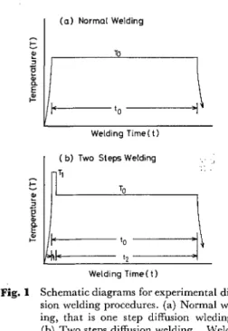
硬 さ,お よ び結 晶 粒度 を示 す.モ リブデ ンの 結 晶粒 は丸 棒 の長 さ方 向 に延 び た形 状 を して い る.イ ンサ ー ト金 属 と して は厚 さ10μ のNi金 属 箔 を 用 い た, 2.2溶 接 方 法 お よび 測 定 方 法 本研 究 で はFig.1に 模 式 的 に 示 した よ うな1段 拡 散 溶 接 法 と2段 拡 散溶 接 法を 用 いた,本 実験 で は,溶 接 中 で の加 圧 力 は 一 定,温 度T1は1200℃,Toは750∼ 1200℃,時 間t1は1分,toは30分 と した.拡 散 溶 接 装 置 は 既報 の もの を用 い,接 合 部 の 温 度 測 定 も 同 じ方 法 で 行 った.真 空 度 は 約1×10〓-4Torrで あ った.室 温 で の 継 手 強 さの 測 定 は イン ス トロ ン型 引張 試験 機 を用 い,溶 接継 手 を そ の ま ま,ゲ ー ジ長 さ30mm,変 形 速 度5.6× 10〓-4sec-1の条 件 で 試 験 した.拡 散溶 接 部 の金 属 組 織 お
Fig. 1 Schematic diagrams for experimental
diffu-sion welding procedures. (a) Normal
weld-ing, that is one step diffusion wleding.
(b) Two steps diffusion welding. Welding
conditions are as follows; to=30 minutes,
t1=1 minute, T1 =1200•Ž and To
=varia-ble. よびNi箔 イ ンサ ー ト金 属 の挙 動 を 明 らか に す る た めに 次 の よ う な実 験 を行 った.光 学 顕 微 鏡 に よ る金 属 組織 の 観 察 を 行 うと と もに,さ らに 日立 製 作所 製HSM-2B型 走 査 型 電 子 顕微 鏡(加 速 電 圧20kVで 使 用)に よ る金 属 組 織 の 観 察,な らび に そ の装 置附 属 の 半 導体 検 出器 を用 いて の 特 性X線 に よ る元 素 分 布 測 定 を 行 った.さ らに, 接合 部破 断 面 に た い して,CuのKα 線 を用 いて 通 常 の デ ィ フ ラ ク トメー タに よ り金 属 間 化合 物 を 同定 す るた め のX線 解 析 を 行 った 。 モ リブデ ンの 結 晶粒 界 で の 脆 化 が 観 測 され た の で,接 合 部 近 辺 で の モ リブデ ン の微 細 組 織 を,日 立 製 作 所 製HU12A型 を用 い加 速 電 圧125kVで 薄 膜 透 過 電 子 顕 微 鏡 観 察 を行 った.
3.実
験 結 果 およ び考 察
3.12段 拡 散 溶 接法 の 効 果 Fig.2は950℃,30分 で1段 拡 散 溶 接 を行 った 場合 の継 手 強 さ,お よ び継 手 の 長 さ変 化(溶 接 変 形 量)と 加 圧 力 の関 係 を示 して い る.加 圧 力 の増 大 と と もに継 手 強 さの 向上 が 見 られ,充 分 な 強 度 を得 る た めに は 大 きな加 圧 力 が 必 要 で あ る こ とを 示 して い る.こ の こ とは 拡 散溶 接 の初 期 に お け る接 合 表 面 の微 細 な凹 凸 部 の 変形 に起 因 す る と考 え られ る金 属 的 接触,あ る い は密 着 化 の段 階 が 継 手 強 さ に大 き く影 響 して い る ことを 示 して い る.し た が って 高 温 強度 の高 い モ リブ デ ン,ハ ステ ロ イXの 拡 散 溶 接 には 密 着 化 を 促進 させ る た め に高 温,高 加圧 力 が 必 要 で あ る.し か し なが ら,ハ ステロ イXは1200℃,溶 接 時 間30分 で は 変 形 が著 し く,ま た モ リブデ ンは再 結 晶 温 度1150∼1200℃ 以 上 で は 再 結 晶 脆 化 が 起 る とされ て い る.し た が って拡 散 溶接 の初 期 段 階 で の両 金 属間 の 密 着 化 を 促 進 さ せ る た め に出 来 るだ け 高 い温 度 で 短 時 間Fig. 2 Tensile strength and percent reduction in
length of the weld joints obtained from one
step diffusion welding as a function of the
magnitude of pressure. Welding
temper-ature and time are 950•Ž and 30 minutes,
加 熱 す る必 要 が あ る.本 研 究で は,2.1kg/mm2の 加 圧 力 の も と で,拡 散 溶 接 の 初期 に お い て1200℃(T1) で1分 間(t1)保 持 した 後,種 々 の 温 度(T0)で29分 間 保 持 す る こ とに よ り拡 散 溶接 を 行 った.こ の1200℃ は ハ ステ ロ イXに と って は 加熱 可 能 な 最 高 温 度 に近 い もの で あ り,圧 力2.1kg/mm2は 次 に述 べ る よ う な 実 験 結 果 よ り決 定 した もの で あ る.Fig.3はT1=1200℃, T0=950℃ と した2段 拡 散 溶 接 法 に よ って 得 られ た 継 手 強 さな らび に溶 接 変形 量 に対 す る加 圧 力 の 関 係 を示 し て い る.Fig.3か ら明 らか な よ うにNi箔 イ ンサ ー ト金 属 の 有 無 に か か わ らず1段 拡 散 溶 接 に よ って4kg/mm2 加 圧 力 の 時 に 得 られ た 強 さと ほ ぼ等 しい 強 さ,あ るい は それ 以 上 の 強 さが2段 拡 散溶 接 法 で は加 圧 力2kg/mm2 で 得 られ て い る.加 圧 力 が2kg/mm2以 上 で は溶 接 変 形 量 が 著 し く増 大 す るば か りで な く,同 時 に継 手 強 さ の 低 下 が 観 測 され た.現 在,こ の低 下 に対 して 明 確 な説 明 は 出 来 な いが,接 合 界 面 で の金 属 間化 合 物 層 の 形成,成 長 あ るい は モ リブデ ンの脆 弱化 が 関 与 して い る も ので あ ろ う と 考 え られ る.し か し なが ら,Fig.3よ り,2段 拡 散 溶 接 法 で は1段 拡 散溶 接法 の場 合 と比 較 して 低 い加 圧 力 で 高 い継 手 強 さが 得 られ る ことが 明 らか で あ り,ま た,今 回 用 い た2段 拡 散 溶 接 法 で は 加圧 力 を2kg/mm2 とす る のが 最 良 で あ る こ とが判 明 した.
Fig. 3 Tensile strength and percent reduction in
length of the weld joints obtained from the
two steps diffusion welding as a function of
the magnitude of pressure. For the first
step welding, the temperature and time
are 1200•Ž and 1 minute, respectively.
Second step diffusion welding was
per-formed for 29 minutes at 950•Ž.
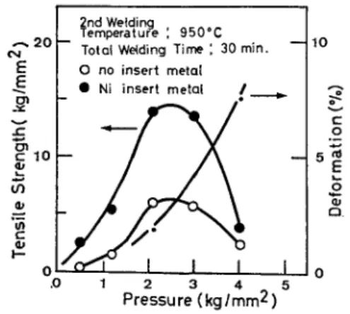
Fig.4は 加 圧 力2.1kg/mm2 ,とした 場 合 の継 手 強 さ な らび に溶 接 変 形 量 と2段 目の 溶 接 温 度(T0)と の 関係 を 示 して い る.図 にはNi箔 イ ンサ ー ト金属 を用 い た 場 合 と用 い な い 場合 の結 果 を 同時 に 示 して い る.溶 接 変 形
Fig. 4 Tensile strength and percent reduction in
length of the weld joints as a function of
the second welding temperatures. First
step welding was performed for 1 minute
at 1200•Ž under the pressure of 2.1 kg/
mm2. Deformation as a percent reduction
in length does not depend on the existence
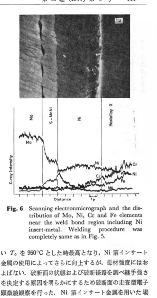
of Ni insert-metal. 量 は いず れ の 場 合 も溶 接 温 度(750∼1050℃)に 関 係 な く比 較 的 小 さ く一 定 で あ った.ま た,継 手 強 さは950℃ の 時 に最 高 と な り,950℃ 以 上 では 低 下 す る.こ の 結 果 は,橋 本,田 沼 に よ り報 告 され て い るモ リブ デ ン板 同 志 の1段 拡 散溶 接 の結 果 と 一 致 して い る.Ni箔 イ ン サ ー ト金 属 を 用 い た 場合 と用 い な い場 合,い ず れ も継 手 強 さ の溶 接 温 度依 存 性 は 同 じ傾 向 を 示 す が,用 い た場 合 は 用 い ない 場 合 に比 較 して 顕 著 な 継 手 強 さの 向上 を示 し て い る. 3.2接 合部 金 属組 織 観 察 およ びNi箔 イ ンサ ー ト金 属 の 挙 動 2段 目 の 溶 接 温 度 を950℃ と し,加 圧 力 を2.1kg/ mm2,時 間 を30分 と した 時 の 接合 部 の金 属 組 織 を走査 型 電 子 顕 微 鏡 に よ り観 察 した.Fig.5お よびFig.6は 接 合 部 断 面 の 金 属組 織 と元 素 分 布 曲 線 を 示 した も ので あ る.Fig.5はNi箔 イ ンサー ト金 属 を 使用 しな い場 合, Fig.6はNi箔 イ ンサ ー ト金 属 を使 用 した 場合 を示 して い る.Fig.5お よ び6は,Ni箔 イ ンサ ー ト金 属 を使 用 し な い場 合 にはMo,Ni,Cr,Feを 含 む 金属 間 化合 物 が 形成 し,Ni箔 イ ンサ ー ト金 属 を使 用 した 場合 に はNi 箔 イ ンサ ー ト金 属 とモ リブ デ ンと の間 にMoとNiか ら な る2元 系 金 属 間 化合 物 が 形 成 す る こ とを 示 して い る. これ らの 金 属 間 化合 物 を同 定 す るた め,継 手 強 さを測 定 した後 の破 断 面 に つ いて,X線 解 析 を 行 った,そ の結 果 をFig.7お よ びFig.8に 示 す.Ni箔 イ ンサ ー ト金 属 を使 用 しな い場 合,ハ ス テ ロ イX側 の破 面 か らは,Mo お よ び顕 著 なP相 の 回折 線 が観 察 され るが,一 方 モ リ ブ デ ン側 の破 面 で はP相 お よ びMoの 回折 線 しか 観 察
溶
接
学
会 誌
第46巻(1977)第9号663Fig. 5 Scanning electronmicrograph and the
dis-tribution of Mo, Ni, Cr and Fe elements
near the weld bond region. Weld joint
was obtained from two steps welding
pro-cedure. First step welding was performed
by 1 minute annealing at 1200•Ž under
the pressure of 2.1 Kg/mm2. Second step
welding was performed by 29 minutes
an-nealing at 950•Ž under the same pressure.
され ず,ハ ス テ ロ イXに よ る回 折 線 は 認 め られ な い.Ni 箔 インサ ー ト金 属 を 使 用 した 場合 に は,ハ ステ ロ イX 側 で は δ-MoNi,Mo,ハ ス テ ロ イX,Niの 回 折 線 が 観 察 され た が,モ リブデ ン側 の 破 面 で はMoと δ-MoNiの 回折 線 しか 観 察 され ず,Niお よ び ハ ス テ ロ イ Xに よ る 回折 線 は認 め られ な い.ま た,イ ンサ ー ト金 属 を 用 い た 場合,用 い な い場 合 の い ず れ の 場 合 で も両 破 断 面 に お い て,非 常 に 弱 い もの で あ るがMoO2の 回 折 線 が 認 め られ る.こ のMoO2は 溶接 中 に形 成 され た も の か,破 断 後,大 気 中で 放 置 され て い る間 に 形成 され た も の か は 明 らか で は な い.こ れ らのX線 解 析 結 果 よ り, Ni箔 インサ ー ト金 属 はP相 の 形成 を 阻 止 し,δ-MoNi 相 を形 成 して い る こ とが 明 らか とな った.P相 の 結 晶構 造 は 明 らかで は な い が,Fe-Cr2元 系 に お け る σ 相 と 似 て,非 常 に硬 く脆 い と報 告 され て い る す な わ ち, Ni箔 イ ンサ ー ト金 属 は脆 弱 なP相 の形 成 を 阻 止 す る こ とに よ り継 手 強 さを 向上 して い る と考 え られ る. 3.3継 手 破 断面 の観 察 前 節 で 述 べ た ご と く,継 手 強 さは2段 拡 散 溶 接 法 を 用
Fig. 6 Scanning electronmicrograph and the dis-tribution of Mo, Ni, Cr and Fe elements near the weld bond region including Ni
insert-metal. Welding procedure was completely same as in Fig. 5.
いT0を950℃ と した 時 最 高 とな り,Ni箔 イ ンサ ー ト 金 属 の 使 用 に よ って さ らに 向上 す るが,母 材 強 度 に は お よば ない 。 破 断 面 の 状 態 お よ び破 断径 路 を調 べ 継 手 強 さ を 決 定 す る原 因 を 明 らか に す るた め破 断面 の走 査 型 電 子 顕 微 鏡 観 察 を行 った.Ni箔 イ ンサ ー ト金 属 を 用 い た 場 合 の モ リブ デ ン側 破 面 の 組 織 の典 型 的 な 例 をPhoto.1 に示 す.Photo.1か ら明 らか な よ うに 金 属 間 化合 物 δ - MoNiの 結 晶 粒 は モ リブ デ ンの 結 晶 粒 に 比 較 して 微 細 で あ り,破 断 は モ リブ デ ン 内 の結 晶 粒 界,お よ び,S-MoNi 内 で起 って い る.こ れ らの 結 果 よ り継 手 に お け る破 断径 路 は δ-MoNi内,モ リブ デ ン の 結 晶粒 界 を通 って い る こ とが 明 らかで あ る.ハ ステ ロ イX合 金 側破 断 面 の観 察 も同 時 に 行 った が,S-MoNi内,Mo結 晶 粒 界 で 破 断 して お り,Ni箔 インサ ー ト金 属 お よび ハ ステ ロ イX内 で は破 断 して い な く,破 断 径 路 は 金 属 間 化 合 物 お よ び モ リブ デ ン結 晶粒 界 を通 って い る こ とが 明 白 とな った.こ の こ とはFig.8のX線 解 析 結 果 で 示 され た よ うに,モ リブデ ン側 で はMoと δ-MoNi,ハ ス テ ロ イX側 で は Mo,δ-MoNi,Ni,ハ ステ ロ イXに よ る 回 折 線 が 観 察 され た こ とと よ く対 応 して い る.Ni箔 インサ ー ト金 属 を 使 用 し な い場 合 は,Fig.7か ら同 様 に モ リブデ ン内, P相 内で 破 断 が 起 った と考 え られ る.
Fig. 7 X-ray diffraction patterns obtained from
the fractured surfaces of weld joints.
Frac-tured surfaces were obtained after the
tensile strength test and Cu Kƒ¿ X-ray was
used. HR indicates the hastelloy alloy X.
Weld joint was obtained from the two steps
welding. First step welding was performed
by 1 minute annealing at 1200•Ž under
the pressure of 2.1 kg/mm2. Second step
welding was performed by 29 minutes
annealing at 950•Ž under the same
pres-sure.
Fig. 8 X-ray diffraction patterns obtained from
fractured surfaces of weld joints including
Ni insert-metal.
Hx indicates the hastelloy
alloy X.
Specimen preparation was
com-pletely same as in Fig. 7.
さ らに,Photo.1に 示 した ごと く破 断 面 のMo内 結 晶 粒 界 に1∼ 数 μ 程 度 の大 き さのvoidが 多 数 観 察 され た.こ れ らのvoidが 接 合 部 近 傍 で のみ 存 在 して い るの か ど うか を 明 らか に す る 目的 で,接 合 界 面 よ り約1mm
Photo. 1 Typical
scanning
electronmicrograph
obtained from the fractured surface of
weld joint including Ni insert-metal.
Photograph
shows the
molybdenum
side of the weld joint.
Photo. 2 Microstructure
of molybdenum in the
weld joint.
Scanning
electronmicro-graphs (a, b) show the fractured
molybde-num surfaces.
(a) molybdenum
side.
(b) hastelloy alloy X side. Transmission
electron micrographs (c,d) were obtained
from thin foil molybdenum base metal
which was cut from inner region of about
1 mm apart from fractured
molybde-num surface.
Selected area diffraction
pattern (e) was obtained from the region
around the void.
の位 置 の モ リブデ ン薄 片 を 切 り出 し,透 過 電 子 顕 微 鏡 に よ る観 察 を行 った.Photo.2は 典 型 的 な 透 過 電 子 顕 微 鏡 観 察 結 果 とモ リブデ ン破 面 の 走査 型 電 子 顕 微 鏡 観 察 結 果 と を比 較 して 示 した.明 らか に透 過 型 電 子 顕 微 鏡 観 察 に よ って も数 μ 程 度 の 大 き さのvoidが 数 多 く観 察 さ れ,走 査 型 電 子 顕 微 鏡 で 認 め られ たvoidと 同一 の も の で あ る と 考 え られ る.Photo.2の(e)は,電 子 線 の透 過 が あ ま り良 くな く,な ん らか の物 質 の 存在 す る と思 わ れ るvoidを 選 び 制 限 視 野 回 折 を 行 った 時 に 得 られ た 回 折 写 真 を示 して い る.そ の回 折 図 形 は 下 に模 式 的 に 示 し たMoO2の 回 折パ ター ンと 比較 的良 い 一 致 を 示 して い る.こ れ らの 結 果 よ り,溶 接 後 に は モ リブデ ンに お け る 結 晶 粒 界 には 多 数 のvoidが 存 在 して お り,あ る もの に
溶 接
学 会
誌
第46巻(1977)第9号665 はMoO2の 存 在 す る こ とが 明 らか と な った.た だ し, モ リブデ ンの 酸 化 は 金 属 表 面 にMoO2,そ の 外 側 に MoO3が 形 成 され る と言 わ れ て い るの で,voidの 原 因 がMoO2の み の形成 お よび そ の 蒸 発,昇 華 に よ る と は結 論 す る こ とは 出来 な い.し か し,モ リブ デ ン母 材 内 の結 晶 粒 界 にお いて も破 断 が進 行 し,そ の結 晶 粒 界 に数 多 くのvoidの 存在 が 確 認 され た た あ,こ れ ら のvoid の形 成 あ る いは成 長 も溶 接継 手 性 能 に な ん らか め悪 影 響 をお よ ぼ して い ると考 え られ る. 4.結 言 本 研究 で は溶 融溶 接 が 困 難 で あ る異 種 金 属 間 の溶 接 の 1例 と して,純 モ りブデ ン と耐 熱 合 金 ハ ステ ロ イXと の 真 空 拡 散溶 接 を試 み,2段 拡 散溶 接 法 の 利 用,Ni箔 イ ンサ ー ト金 属 の挙 動,モ リブデ ンの 脆 弱 化 に つ い て 検 討 を行 った.得 られ た結 果 を要 約 す る と以 下 の ご と くで あ る. 1)高 温 短 時 間 加熱 を含 む2段 拡 散 溶 椄 法 の 利 用 に よ り,溶 接 変形 量 を大 き くす る こ と な く両 金 属 間 の 密 着 化 を促 進 し,継 手 強 さを向 上 さ せ る. 2)Nibイ ンサ ー ト金 属 は 脆 弱 なMo,Ni,Cr,Fe を含 む 金 属 間 化合 物P相 の形 成 を阻 止 し,継 手 強 さを 向 上 させ る.但 し,Ni箔 イ ンサ ー ト金 属 は モ リブ デ ン と の 間 に2元 系 金 属 間化 合 物 δ-MoNi相 を 形成 す る. 3)継 手 に お け る破 断は 金 属 間 化 合 物 層 お よ び モ リブ デ ン内 の 結晶 粒 界 で起 って お り,継 手 強 さを 向上 させ る た め に は 脆 弱 な金 属 間 化合 物 を形 成 し ない イ ンサ ー ト金 属 の 検 討 お よび モ リブ デ ン 自身 の 脆 弱 化 を 阻止 す る方 法 を検 討 しな けれ ば な らな い. 4)モ リブ デ ン側 破 面 お よ び モ リブ デ ン母 材 内 の 結 晶 粒界 に数 多 くのvoidの 存在 が 確 認 され,void内 で の MoO2の 存 在 が見 い 出 され た.こ れ らのvoidの 存 在 が 継 手 強 さの低 下 に なん らか の 関係 が あ る も の と考 え られ る.参
考
文 献
1) 日 本 原 子 力研 究所 資料;核 融 合 研 究 開 発 の 現 状,(1975).2) N.F.Kazakov;Diffusionaya Svarka Vakuume,
Mashionostroyniye,(1966), 3) 圓城 敏 男,池 内 建 二,飯 田 孝 道,金 井 雅 仁,荒田 吉 明;Ti-15% Mo-5%Zr合 金 と軟 鋼(0.06%C)と の 拡 散 溶 接 に 関 す る 研 究 ,高 温学 会誌,1-3(1976)36-48. 4) 圓城 敏 男,池 内 建 二,金 井 雅 仁,丸 山敏 治;チ タ ン と アル ミ ニ ウ ム と の拡 散 溶 接,本 誌,45-2(1977)82-89. 5) 橋 本 達 哉,田 沼 欣 司;モ リブデ ンの 拡 散 接 合,本 誌,37(1968) 1345-1352.
6) T. Wada ; Metals Handbook, 8th edition, Vol. 8, Metallography, Structures and Phase Diagrams, ASM, Metals Park, Ohio (1973), 426.
7) C. B. Shoemaker and D.P. Shoemaker ;The Crystal Structure of the ƒÂ Phase, MoNi, Acta Cryst., 16 (1963), 997-1009,
8) E. A. Gulbransen and S. A. Jansson ;Oxidation of Metals and Alloys, ASM, Metals Park, Ohio (1971) 75-80