Morphology of Drawn Syndiotactic Polypropylene Films
J. Harasawaa, H. Ueharaa, T. Yamanobea, T. Komotoa,*, M. Teranob
a Department of Chemistry, Gunma University, 1-5-1 Tenjin-cho, Kiryu, Gunma 376-8515, Japan
b
School of Materials Science, Japan Advanced Institute of Science and Technology, 1-1 Asahidai, Tatsunokuchi, Ishikawa 923-1292, Japan
* Corresponding author. Tel.: +81-277-30-1330; fax: +81-277-30-1333 E-mail address: [email protected]
Abstract
Morphological studies were made to investigate the drawablity of melt-quenched (MQ) and slowly cooled (MSC) films of syndiotactic polypropylene (sPP) with a high syndiotactic pentad fraction. Transmission electron microscopy (TEM) using the ruthenium tetraoxide staining and ultrathin sectioning method revealed that amorphous chains as the matrix of MQ film played a role in drawability of the film by their alignment to machine direction MD and partial crystallizations into nanofibrils. On the other hand, the initial strain induced rotations of clusters of long lamellar crystals as the major entity of MSC film, accompanying breaks of long lamellae and formation of crazes and microvoids at the cluster boundary. Compared with a homogeneous thinning of MQ film by drawing, ca. 100 nm-thick layer slips along MD and parallel to the film surface took place in MSC film. This gave rise to formation of V-shaped bent lamellar morphology and their further break into a smaller cluster of stacked lamellae which were aligned oblique by ca. 35o from MD. With elongation, some
to the remained oblique lamellae and others parallel to MD in region where lamellar morphology almost disappeared. No chain slips in the nanofibrils can be related to a low elongation at break, i. e., a low ductility of sPP films. The lower elongation at break for MSC film than for MQ one can be interpreted by microvoids initially formed in the neck region and later moved to the fully drawn part, the microvoids initiating the break of the drawn film.
Keywords: Syndiotactic polypropylene; Morphology; Drawing; Deformation
1. Introduction
A widely used commercial polypropylene is isotactic one (iPP) which has a 31 helical
conformation in crystalline state [1], melting temperature Tm of ca. 170oC and a wide molecular
weight distribution due to the multi-site activities of the polymerization catalysts. On the other hand, syndiotactic polypropylene (sPP) obtained by single-site metallocene catalysts has a narrow molecular weight distribution and a high syndiotactic stereoregularity, the latter depending on catalyst [2]. Tm of sPP also depends on the stereoregularity. For example, sPP with a high syndiotactic pentad fraction (rrrr) of 0.92, crystallized at 140oC for 24 h, gives Tm of ca. 161oC [3].
As for the molecular structure of sPP in crystals, planner zigzag (all-trans) and 41 helical
conformations have been reported. The planner zigzag conformation is taken in samples cold-drawn below the glass transition temperature Tg of ca. 0oC [4-6]. Loos et al. [6] reported that the zigzag
conformation was not changed by annealing at 60oC above Tg when the sample was kept strained
during annealing, while the same annealing with relaxed sample exhibited shrinkage, accompanying a partial conformational transition from zigzag to 41 helix.
Cells I, II and III are known as unit cells of the most stable form I of sPP [7], depending on the helical sense and packing of the right- and left-handed 41 helical chains. Cell II and cell III are
respectively [3,8]. Thus, cell II is thought to be formed under such a usual crystallization condition as slow and rapid coolings to room temperature from melt.
Tensile properties are the important characteristics of sPP. Sakata et al. [9] reported the absence of an α relaxation and an effective crystalline c-slip process in sPP which explain the relatively poor drawing behavior as compared with iPP. Uehara et al. [10] reported that the modulus was remarkably lower for sPP than for iPP, while the tensile strengths were not significantly different.
There have been no reports on morphological study by transmission electron microscopy (TEM) relevant to deformation of sPP bulk samples. In the previous paper [3], we reported that a TEM study using the ruthenium tetraoxide (RuO4) staining and ultrathin sectioning method led to the detailed
mechanism of isothermal crystallization of sPP from melt. In this paper, we will report a TEM study on the mechanism for morphological change of sPP sample by drawing.
2. Experimental
2.1 Syndiotactic polypropylene (sPP) samples
sPP with number average molecular weight Mn of 45,000, weight average molecular weight Mw of 76,500, a molecular weight distribution index Mw/Mn of 1.7 and a syndiotactic pentad fraction (rrrr) of 0.92 was used in this study. sPP containing a small amount of antioxidant was melt pressed at 200
o
C for 5 min and then quenched in iced water or slowly cooled to room temperature. The quenched and slowly cooled specimens are denoted as MQ and MSC, respectively, here. Crystallinity of MQ and MSC samples was ca. 50 % and ca. 30 %, respectively, as estimated from densitometry at 25oC in
a density-gradient column consisting of carbon tetrachloride and heptane mixtures. 2.2 Drawing
MQ and MSC films of 40 mm long, 2 mm wide and 0.3 mm thick were used for the tensile measurements at a strain rate of 0.5 (cross-head speed of 10 mm/min) in a Toyo Boldwin Tensilon II. The films of 20 mm long were each drawn to ca. 300 % at room temperature to prepare specimens for
morphological measurements.
2.3 Polarized optical microscopy (POM)
POM of the drawn samples was made around the neck zone with a polarizer at 0o and 45o to the
machine direction MD in an Olympus BX50 optical microscope. 2.4 Wide-angle X-ray diffraction (WAXD)
WAXD patterns of undrawn and drawn sPP films were recorded on a flat camera in a Rigaku Geigerflex X-ray diffractometer using CuKα beam generated at 40 kV and 130 mA. The X-ray beam was irradiated perpendicular to the edge of the film. WAXD profiles were also recorded for the undrawn samples.
2.5 Differential scanning calorimetry (DSC)
DSC thermograms were recorded on the undrawn and drawn specimens in a Perkin-Elmer Pyris 1 DSC equipment at a heating rate of 20oC/min over a temperature range from 25 to 200oC in nitrogen
atmosphere.
2.6 Transmission electron microscopy (TEM)
The undrawn and drawn specimens were embedded in an epoxy resin, trimmed in a liquid nitrogen atmosphere and stained at 60oC for 3 h by ruthenium tetraoxide (RuO4) in its vapor phase of the
solution prepared by the method according to Trent et al. [11] Ultrathin sections of these specimens obtained using a diamond knife at room temperature were collected on copper grids and subjected to TEM observations in a JEOL JEM-1200EXS transmission electron microscope at an acceleration voltage of 80 kV. Thickness of the crystalline parts of edge-on lamellae seen as bright lines in TEM micrographs was measured as the lamellar thickness.
3. Results and discussion
3.1 Tensile properties
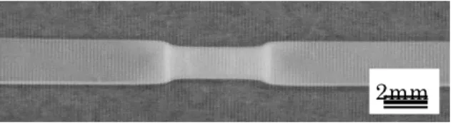
commenced without whitening of the original transparent film. On the other hand, whitening of the semitransparent MSC film occurred before necking and remained in the undrawn and drawn parts during drawing as is seen in Fig. 1. Breaking took place in the drawn part both in MQ and MSC films.
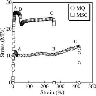
They had tensile properties of the films as shown in Fig. 2. The MQ film was found to be deformed with elongation in a process: 1) the initial elastic region, 2) the yield point A at a strain as low as ca. 15 %, 3) the formation and growth of necking with a constant stress of ca. 10 MPa up to a strain of ca. 270 % at B, and then 4) a gradual increase in stress with strain to break at ca. 420 % in strain at C. On the other hand, the MSC film showed a deformation process: 1) the initial elastic region, 2) the first yield point A at a strain of ca. 20 % where no necking took place, 3) the second yield point B at a strain of ca. 30 %, beyond which necking commenced, accompanying an abrupt decrease in stress, and 4) a propagation of necking with a constant stress of ca. 23 MPa with strain to break at ca. 260 % in strain at C. The yield stress and the stress during necking were higher for MSC than for MQ, while the elongation at break was opposite. These differences in tensile properties might be related to the difference in crystallinity between these specimens.
3.2 Optical morphology
Fig. 3 shows POM micrographs of the region including the neck zone of the drawn MQ and MSC films, where the machine direction MD and the directions of polarizer and analyzer are also shown. It was found in the drawn MQ film that a dark POM image of the undrawn part suggests an isotropic entity with a low crystallinity and a bright image of the drawn part indicates a chain orientation along MD. A neck region of ca. 30 µm long is also seen with an intermediate brightness in the drawn MQ film.
As for the drawn MSC film, an anisotropic entity which may consists of spherulites is seen bright in the undrawn part and a bright image with striations along MD in the drawn part. The striation image suggests higher molecular chain orientations in drawn MSC film than in MQ one. It was also
found that a neck region with ca. 20 µm long is smaller in size for MSC than for MQ, indicating a low ductility of MSC.
3.3 Structure
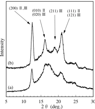
As is shown in Fig. 4, WAXD profiles of the isotropic undrawn MQ and MSC samples indicate that the MQ film consists of cell II structure and the MSC film a mixture of cell II as the major fraction and cell III as a minor one. Fig. 5 shows WAXD patterns and indexing of the reflections of the drawn parts of these films and indexing of the intense reflections based on cell II structure as will be mentioned later. The X-ray diffraction patterns of the drawn parts of both samples suggest that the oriented amorphous structure is dominant.
As for WAXD pattern of the drawn part of MQ film, equatorial sharp (200) and broad (010) reflections and a meridional sharp (002) reflection, based on cell II structure, indicate a high c-axis orientation along MD. On the other hand, equatorial arc (200) and broad (010) reflections and no meridional (002) reflection indicate a less c-axis orientation for the drawn MSC. The assignment of the reflections mentioned above will be discussed below.
It is also noted that the cell II (111) and/or cell III (121) reflections appeared different between the drawn MQ and MSC films. That is, the drawn MQ film gave the corresponding four off-meridional reflections, which are typical of an inclination of the planes from the (001) plane or MD. On the other hand, the drawn MSC film gave corresponding two meridional reflections in addition to the off-meridional ones. The azimuthal angle of the off-meridional reflections from the meridian, i. e., MD was measured as ca. 55o. The angle between the off-meridional cell II (111) or cell III (121)
planes and the meridian was calculated as 54.8o [12] based on cell II with a = 1.45 nm, b = 0.56 nm
and c = 0.74 nm or cell III with a = 1.45 nm, b = 1.12 nm and c = 0.74 nm [13], respectively.
From their X-ray studies, Loos et al. [6] reported the dominant transformation from the all-trans (zigzag) structure to cell II and a minor one to cell III, the latter being assigned by a weak (011) reflection, when an sPP film drawn below Tg of 0oC was annealed at 100oC. The dawn and
100oC-annealed film of Loos et al. [6] gave an X-ray diffraction pattern indicating a crystallinity
much higher than those for the films drawn at room temperature in this study. It seems reasonable, therefore, that the structure of the present drawn films take cell II rather than cell III, the latter being obtained under such a condition as isothermal crystallizations above 120oC [3].
The four off-meridional reflections indicate that the c-axis is highly oriented along MD as was found in the drawn MQ film. The additional meridional reflections for the drawn MSC film indicate orientations of c-axis inclined ca. 55o from MD. In other words, it can be anticipated from the
meridional cell II (111) reflections that some lamellar crystals inclined ca. 35o from MD are formed
in the drawn part of the MSC specimen. 3.4 Thermal properties
Fig. 6 shows DSC thermograms of the undrawn, necked and drawn regions of MQ and MSC films. The DSC thermogram (a) of the undrawn MQ specimen consists of an endothermic peak at Tm of 144.5oC and an endotherm over a wide temperature range below Tm, suggesting small lamellar
crystals with an average crystalline thickness as thin as ca. 4 nm according to our morphological study [3]. This is nearly half the thickness of crystals formed by isothermal crystallization of the same sPP at 140oC for 24 h, which showed a sharp endothermic peak at Tm of 161oC [3]. The
thermogram (b) of the neck region of the MQ film was similar to the undrawn one, suggesting a little rearrangement of the original crystals. An endotherm at ca. 138oC, which is comparable to that at ca.
144oC, in the thermogram (c) of the drawn part may indicate a formation of crystallites due to a
partial intermolecular crystallization of oriented amorphous chains by drawing above Tg of 0oC
rather than a break of the original thin crystals or thinning of lamellar crystals, the latter of which usually interprets a decrease in melting temperature.
The thermogram (d) of the undrawn MSC specimen, which gave Tm of ca.149oC, is similar to that
for crystals formed by isothermal crystallization of the same sPP at 110oC for 24 h, suggesting an
interpreted by the same reason as for MQ. As for the thermogram (f) of the drawn part of MSC film, the main endothermic peak appeared at ca. 146oC, which is lower by ca. 3oC than for the undrawn
one. Taking into account no crystalline c-slip process by drawing [9], the decrease in Tm by drawing may be due to a break of the original lamellar crystals into smaller ones. An additional shoulder peak appeared at ca. 141oC may indicate melting of crystals formed by a partial intermolecular
crystallization of oriented amorphous chains as in the case of the drawn MQ. 3.5 TEM morphology of drawn MQ films
TEM micrographs of the edge views of the undrawn, neck and drawn regions of the MQ film are shown in Fig. 7, where lamellar crystals are seen as bright thin crystalline parts sandwiched by dark amorphous parts. In the undrawn part (a) are seen randomly oriented short lamellae with an average thickness of ca. 4 nm, which coincides with the value estimated from its DSC thermogram (Fig. 6 (a)). A similar morphology was found in the neck region (b) except that a fraction of lamellae aligned perpendicular to MD tends to increase and their lengths decreased a little. In the micrograph of the drawn part (c), the lamellar crystals seem to be broken into finer crystallites with less image contrast between the crystalline and amorphous parts, where the fine lamellae are almost aligned perpendicular to MD and the crystal thickness was unchanged. A close look at the micrograph reveals a formation of nanofibrils of ca. 1 nm thick which are aligned parallel to MD. These nanofibrils are thought to be formed by the partial intermolecular crystallization of oriented amorphous chains. This coincides with the X-ray and DSC results mentioned above.
3.6 TEM morphology of drawn MSC films
As was anticipated from DSC results, long lamellar crystals with an average thickness of ca. 5 – 6 nm are seen in Fig. 8 (a) for the original, slowly crystallized MSC film.
A TEM micrograph obtained from the undrawn, whitened region, though not shown here, showed a morphology that the lamellae are oriented to some extent to MD and microvoids were formed place to place. This is similar to the case of the neck region as will be mentioned below.
Fig. 8 (b) shows a morphology of the neck region that broken lamellar crystals with the same thickness as those for the original one are aligned nearly parallel to MD, accompanied by formation of microvoids with bright images. Some dark parts thereby are thought to be crazes highly stained by RuO4. This morphology is very similar to that for a stress-whitened polymer blend consisting of iPP,
polyethylene and ethylene-propylene copolymer [14]. This result indicates that a small strain induces rotation of lamellae and a formation of crazes and microvoids where large strains might be locally concentrated.
Fig. 8 (c) indicates a further deformation of the entity near the boundary between the neck zone and the drawn part. The lamellar crystals were further broken smaller in size without a change in thickness of the remaining lamellae. It is noted, however, that most lamellae are not aligned parallel but oblique to MD. A unique morphology of sharply bent lamellae like a letter “V” is observed in the center of the micrograph. The inner angle of the bent lamellae is ca. 70o, indicating the lamellar
oblique angle of ca. 35o from MD, i. e., the oblique angle of c-axis from MD being ca. 55o for these
crystals. This angle fairly coincides with the value estimated from the meridional cell II (111) reflection in the WAXD pattern of drawn MSC film.
The bent lamellae can be formed only by locally different strains applied to such straight lamellae seen in Fig. 8 (b). The size of each straight part of the bent lamellae in the direction perpendicular to MD, that is, in the direction of film thickness, is estimated as ca. 100 nm from the micrograph. This also suggests that slips of neighboring layers of ca. 100 nm thick took place parallel to both MD and the film surface. One can say that this sort of layer slips gives rise to thinning of the original film. It is of great importance to say that the necking of MSC film does not take place by a homogeneous thinning of film but by ca.100 nm-thick layer slips due to differences in local strains along MD It was also found in Fig. 8 (c) that some nanofibrils are aligned perpendicular to the olique lamellae thereby and others parallel to MD in the region where lamellar morphology almost disappeared by breaking.
Fig. 8 (d) shows the morphology of the drawn part of MSC which reveals that clusters of lamellae oblique to MD at almost same angles as in Fig. 8 (c) still remained and bent lamellae disappeared. The lamellar lengths became shorter than those for Fig. 8 (c). This result suggests that clusters of straight lamellae are bent by shear due to locally different strains and then broken into clusters of shorter straight lamellae by further strains. It is also suggested that strained, amorphous molecular chains generated from the broken lamellae were partially crystallized into nanofibrils aligned perpendicular to the remained lamellae thereby. These nanofibrils are thought to resemble the so-called tie fibrils. In Fig. 8 (d) are also seen nanofibrils aligned parallel to MD in the region where lamellar morphology almost disappeared.
In TEM micrographs of a drawn part away from the neck zone for MSC film, though not shown here, are seen a non-lamellar but nanofibrillar entity as the major fraction, a less amount of clusters of oblique lamellae and very short lamellae of a few nm thick which are nearly parallel aligned to MD. It is pointed out that lamellae aligned perpendicular to MD was completely absent as in the cases of neck zone and drawn region close to the neck.
As was revealed from TEM and WAXD data, the absence of lamellae aligned perpendicular to MD and the major c-axis orientation along MD can be accounted for by such crystals as MD-oriented nanofibrils newly formed via a break of the original lamellae and the subsequent partial crystallization of amorphous chains formed therefrom.
3.7 Deformation mechanism for MQ film
Along the line of arguments mentioned above, the common characteristics of the MQ and MSC films revealed in this study are summarized as the major cell II structure, rotations and breaks of lamellae, formation of nanofibrils by partial intermolecular crystallization of oriented amorphous chains formed from broken lamellar crystals and low elongations at break, the low elongation being interpreted by the absence of the α relaxation and the effective crystalline c-slip process according to literatures [9,10],.
Crystallinity of 30 % indicates that major entity of MQ film is amorphous. Namely, short lamellar crystals of ca. 4 nm thick, which have cell II structure, are randomly dispersed in the dominant amorphous matrix. The amorphous chains begin to be oriented to MD in the initial stages of drawing. With increasing stain, the fine lamellae tend to rotate and are aligned perpendicular to MD by tensions via interlamellar oriented amorphous chains. The lamellar rotations take place in the neck and neighboring drawn parts. Although crystalline chains hardly slip by strain, the present TEM morphology revealed a gradual break of lamellae. This leads to formation of amorphous chains therefrom and a decrease in lamellar size, while the lamellar thickness does not change. The oriented amorphous chains tend to be partially crystallized into nanofibrils of ca. 1 nm thick with cell II structure. A very small amount of visible microvoids and crazes in drawn part suggests a homogeneous deformation and thinning of the film.
3.8 Deformation mechanism for MSC film
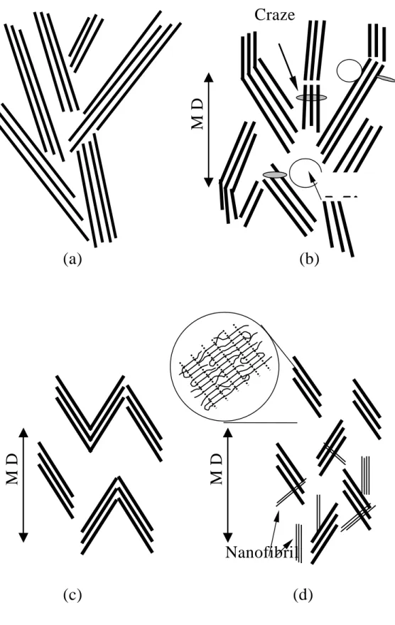
Although the crystallinity was only ca. 50 %, well-grown long lamellar crystals of ca. 5 – 6 nm thick and with cell II structure are densely formed as the major entity in the original MSC film. Thus, the initial strain seems to be applied directly to these lamellar crystals, while it was applied to the amorphous matrix in case of MQ film. This can be accounted for by the large stress to yield, which attained to a value ca. 2.5 times that for MQ film. The deformation mechanism for MSC film is postulated in Fig. 9, where the original lamellar arrangement is shown in (a).
As is illustrated in Fig. 9 (b), the tensile properties and TEM micrographs revealed that clusters of lamellae rotate and tend to be oriented to some extent along MD at the first yield point with strain of ca. 20 % and then crazes and microvoids are formed by the break of long lamellae to shorter one in the neck region after the second yield point with strain of ca. 30 %. Microvoids formed in this neck region should move to the fully drawn region, because the entity in the neck region turns to that in the drawn region by further drawing. In fact, microvoids were found in the whole regions from the neck region to the drawn one.
A further elongation in the neck region induces ca. 100 nm-thick layer slips along MD and parallel to film plane due to local strain differences. As the layer thickness is smaller than the lamellar cluster size, the shear causes sharp bending of the stacked lamellae in a cluster, giving rise to formation of V-shaped stacked lamellae as is illustrated in Fig. 9 (c). The angle between the direction of each lamella and MD is ca. 35 o and accordingly the c-axis of the oblique, stacked lamellae is inclined ca.
55 o from MD.
In most cases where the shear exceeds that for formation of the bent lamellae, breaks of the bent lamellae take place to become a cluster of stacked ones, the alignmenet of which is kept oblique to MD as is shown in Fig. 9 (d). TEM micrographs revealed that nanofibrils such as the so-called tie fibrils are formed to be aligned perpendicular to the remained stacked lamellae in the lamellar region, while they are nearly parallel to MD in the entity where lamellar morphology has almost disappeared. The amount of the oblique lamellae decreases with increasing strain, indicating a further break of such oblique lamellae into nanofibrils with the same cell II structure. At the end of drawing close to fracture of the film, the major fractions seem to be nanofibrils and lamellae.
Although the sPP chains does not undergo the c-slip [9], i. e., a chain sliding in the crystalline state by strain probably due to no α relaxation [10], a partial or gradual transformation of lamellar crystals to nanofibrils by an excess strain was revealed in this study. If the amorphous chains exclusively take the dominant role in elongation of sPP film, the measured elongation to ca. 300 – 400 % at break would have not attained. Thus, the elongation of the sPP film can be also accounted for by rotations and partial breaks of lamellar crystals transformed into nanofibrils. Supposed that no chain slidings in the nanofibrils take place, the fracture should start at microvoids remained in the fully drawn part. The lower drawability of MSC film than MQ film is thought to be due to the presence of more microvoids than in the drawn MQ film.
The low drawability of sPP was mainly studied by TEM of the RuO4-stained and ultrathin
sectioned specimens obtained from the films drawn at room temperature, combined with the data obtained by other physical measurements. The TEM morphology revealed the detailed mechanism for deformation that not only the rearrangement of the amorphous chains to be aligned along MD but also the rotation and break of lamellar crystals caused formation of amorphous chains and microvoids. The former amorphous chain rearrangement played the dominant role in deformation of melt-quenched film (MQ) with a homogeneous film thinning, while the latter transformation of crystals was also an important reason for deformation of the film slowly cooled from melt (MSC). In both cases, amorphous chains were partially crystallized into oriented nanofibrils and thereafter the films were broken. The lower drawability of MSC film can be explained by the presence of microvoids which were initially formed in the neck region and then moved to the fully drawn region as is summarized in Fig. 9.
References
[1] G. Natta, P. Corradini, Nuovo Cimento, Suppl., 15 (1960) 40.
[2] J. A Ewen, R. L. Jones, A.Razzavi, J. Am. Chem. Soc., 110 (1988) 6255.
[3] J. Harasawa, H. Uehara, T. Yamanobe, T. Komoto, J. Electron Micros., to be accepted. [4] G. Natta, M. Peraldo, G. Allegra, Makromol. Chem., 75 (1965) 215.
[5] Y. Chatani, H. Maruyama, K. Noguchi, T. Asanuma, T. Shiomura, J. Polym. Sci., Part C: Polym. Lett., 28 (1990) 393.
[6] J. Loos, A. Hückert, J. Petermann, Colloid Polym.Sci., 274 (1996) 1006. [7] C. De Rosa, P. Corradini, Macromolecules, 26 (1993) 5711.
[8] A. J. Lovinger, B. Lotz, D. D Davis,M. Schumacher, Macromolecules, 27 (1994) 6603. [9] Y. Sakata, A. P. Unwin, I. M. Ward, J. Mater. Sci., 30 (1995) 5841.
[10] H. Uehara, Y. Yamazaki, T. Kanamoto, Polymer, 37 (1996) 57.
[11] J. S. Trent, J. I. Scheinbeim, P. R. Couchman, Macromolecules, 16 (1983) 589.
[12] For example, the azimuthal angle ψ between the off-meridional (111) reflections and the meridian corresponds to that between the (111) and (110) planes. Thus, the angle is calculated from the following equation for orthorhombic unit cell.
cos ψ = (h1h2/a 2 +k1k2/b 2 +l1l2/c 2 ) / [(h1/a) 2 +(k1/b) 2 +(l1/c) 2 ]1/2[(h2/a) 2 +(k2/b) 2 +(l2/c) 2 ]1/2
where (h1k1l1) and (h2k2l2) denote Miller indices of two planes, and a, b and c the unit cell
dimensions.
[13] P. Corradini, G. Natta, P. Ganis, P. A. Temussi, J. Polym. Sci., Part C, 16 (1967) 2477. [14] H. Sano, T. Komoto, Denshi Kenbikyo, 32 (1997) 71.
Figure captions
Fig. 1 An MSC film slowly crystallized from melt and drawn at room temperature.
Fig. 2 Stress vs. strain plots for MQ and MSC films drawn at room temperature. See text for notations A, B and C.
Fig. 3 Polarized optical micrographs of drawn MQ ((a) and (b)) and MSC ((c) and (d)) films as observed perpendicular to the film surface. The corresponding relation among the machine direction MD, and directions of polarizer (P) and analyzer (A) is also illustrated.
Fig. 4 WAXD profiles of the original MQ (a) and MSC (b) films. Miller indices based on cell II and cell III are given to the diffraction peaks.
Fig. 5 WAXD patterns of edge-views of drawn MQ (a) and MSC (c) films. Indexing of intense reflections assigned based on cell II structure is also illustrated (see text).
Fig. 6 DSC thermograms of the undrawn (a and d), neck (b and e) and drawn (c and f) regions of MQ (a – c) and MSC (d – f) films. Heating rate: 20oC/min.
Fig. 7 TEM micrographs of the undrawn (a), neck (b) and drawn (c) regions of MQ film.
Fig. 8 TEM micrographs of the undrawn (a), neck (b), more drawn neck (c) and drawn (d) regions of MSC film. The morphologies are schematically illustrated in Fig. 9.
Fig. 9 Schematic illustrations for deformation of the entity of MSC film, corresponding to TEM micrographs shown in Fig. 8. (a): Arrangement of the original lamellae, (b): rotation of clusters of lamellae, accompanying breaks of lamellar crystals at which crazes seen dark and microvoids seen bright are formed, (c) formation of V-shaped bent stacked lamellae due to ca. 100 nm-thick layer slips and (d) further breaks of clusters of lamellae and formation of nanofibrils aligned perpendicular to the remaining lamellae as well as those parallel to MD.
Harasawa et al. Fig. 1 2mm
Fig. 1 An MSC film slowly crystallized from melt and drawn at room temperature.
Harasawa et al. Fig. 2
0
100
200
300
400
500
0
10
20
30
Strain (%)
S
tr
es
s
(M
P
a)
A B C A B C○ MQ
□ MSC
Morphology of Drawn Syndiotactic Polypropylene Films
Fig. 2 Stress vs. strain plots for MQ and MSC films drawn at room temperature. See text for notations A, B and C.
A
P
Sample MDA
P
Sample MD Undrawn part Drawn part Drawn part Drawnpart Drawn part
Undrawn part Undrawn part Undrawn part Necking part Necking part Necking part Necking part
(a)
(d)
(c)
(b)
Harasawa et al. Fig. 3 Fig. 3 Polarized optical micrographs of drawn MQ ((a) and (b)) and MSC ((c) and (d)) films as observed perpendicular to the film surface. The corresponding relation among the machine direction MD, and directions of polarizer (P) and analyzer (A) is also illustrated.Harasawa et al. Fig. 4 5 10 15 20 25 30
2θ (deg.)
In
te
n
si
ty
(a) (b) (111) Ⅱ (121) Ⅲ (211) Ⅲ (010) Ⅱ (020) Ⅲ (200) Ⅱ,ⅢMorphology of Drawn Syndiotactic Polypropylene Films
Fig. 4 WAXD profiles of the original MQ (a) and MSC (b) films. Miller indices based on cell II and cell III are given to the diffraction peaks.
M
a
ch
in
e
d
ir
e
ct
io
n
M
a
ch
in
e
d
ir
e
ct
io
n
M
a
ch
in
e
d
ir
e
ct
io
n
M
a
ch
in
e
d
ir
e
ct
io
n
(a
(010)
(010)
(010)
(010)
(010)
(010)
(010)
(010)
(002)
(002)
(002)
(002)
(200)
(200)
(200)
(200)
(111)
(111)
(111)
(111)
(200)
(200)
(200)
(200)
(111)
(111)
(111)
(111)
(b)
(201)
(201)
(201)
(201)
(201)
(201)
(201)
(201)
Harasawa et al. Fig. 5 Fig. 5 WAXD patterns of edge-views of drawn MQ (a) and MSC (c) films. Indexing of intense reflections assigned based on cell II structure is also illustrated (see text).Harasawa et al. Fig. 6 80 100 120 140 160 180
Temperature (℃)
E
n
d
o
th
er
m
ic
(a)
(b)
(c)
(d)
(e)
(f)
Morphology of Drawn Syndiotactic Polypropylene Films
Fig. 6 DSC thermograms of the undrawn (a and d), neck (b and e) and drawn (c and f) regions of MQ (a – c) and MSC (d – f) films. Heating rate: 20oC/min.
Morphology of Drawn Syndiotactic Polypropylene Films
Harasawa et al. Fig. 8 Morphology of Drawn Syndiotactic Polypropylene Films Fig. 8 TEM micrographs of the undrawn (a), neck (b), more drawn neck (c) and drawn (d) regions of MSC film. The morphologies are schematically illustrated in Fig. 9.
Nanofibril
Craze
M
D
M
D
M
D
(a)
(b)
(d)
(c)
Micro
Micro
Micro
Micro
Harasawa et al. Fig. 9Fig. 9 Schematic illustrations for deformation of the entity of MSC film, corresponding to TEM micrographs shown in Fig. 8. (a): Arrangement of the original lamellae, (b): rotation of clusters of lamellae, accompanying breaks of lamellar crystals at which crazes seen dark and microvoids seen bright are formed, (c) formation of V-shaped bent stacked lamellae due to ca. 100 nm-thick layer slips and (d) further breaks of clusters of lamellae and formation of nanofibrils aligned perpendicular to the remaining lamellae as well as those parallel to MD.