PAPER
Joint Special Section on Opto-electronics and Communications for Future Optical NetworkComparison of Optical Transport Technologies for Centralized Radio Access Network Using Optical Ground Wire
Kensuke IKEDA†a),Member, Christina LIM††b), Ampalavanapillai NIRMALATHAS††c), andChathurika RANAWEERA†††d),Nonmembers
SUMMARY Communication networks for wide-scale distributed en- ergy resources (DERs) including photovoltaics (PVs), wind, storage and battery systems and electric vehicles (EVs) will be indispensable in future power grids. In this paper, we compare optical fronthaul networks using existing optical ground wires (OPGWs) for centralized radio access net- work (C-RAN) architecture to realize cost effective wireless communica- tion network expansion including low population area. We investigate the applicability of optical data transport technologies of physical layer split (PLS), analog radio-on-fiber (ARoF), and common public radio interface (CPRI). The deployment costs of them are comparatively analyzed. It was shown that physical layer split and analog radio-on-fiber with subcarrier multiplexing (SCM) result in lower cost than other technologies.
key words:centralized radio access network (C-RAN), optical ground wire (OPGW), radio on fiber (RoF), smart grid
1. Introduction
Revolution on power grid has been progressing to realize a low carbon emission society and resilient power supply.
The wide-scale distributed energy resources (DERs) includ- ing photovoltaics (PVs), wind, battery systems and plug-in electric vehicles (EVs) have been consistently increasing.
It is also anticipated that these DERs cooperate with power grid in real time for stable power supply because the power generation of PV and wind vary regardless of demand of electricity. This means that the DERs need a widespread communication network. Therefore, the future electrical grid strongly depends on information and communication technology (ICT) more than the existing power grid[1].
Ultra-reliable low-latency communication (URLLC) is required in mission-critical communication such as protec- tion and operation of power grid. Electric power compa- nies already have their own private URLLC networks for their conventional power grids. If the DERs became domi- nant part of power grid, it would be necessary to extend the URLLC communication networks for wide-spread DERs as
Manuscript received December 20, 2019.
Manuscript revised April 3, 2020.
Manuscript publicized May 22, 2020.
†The author is with Central Research Institute of Electric Power Industry, Yokosuka-shi, 240-0196 Japan.
††The authors are with The University of Melbourne, Mel- bourne, Australia.
†††The author is with Deakin University, Geelong, Australia.
a) E-mail: [email protected] b) E-mail: [email protected] c) E-mail: [email protected] d) E-mail: [email protected]
DOI: 10.1587/transcom.2019OBP0004
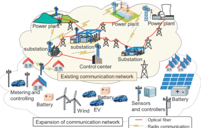
Fig. 1 Existing communication network in power grid.
shown in Fig. 1.
In some reports[2]–[4], it is shown that DERs require 99.99% or 99.999 of reliability and several tens milliseconds order of latency as shown in Table 1, because unavailabil- ity and large latency may lead instability of the power grid, electric outage and damage on equipment. Therefore, par- allel use of commercial mobile networks, the public safety mobile broadband network[5]and utility-owned/controlled private networks are recommended [6]. The allowable la- tency in radio access become shorter than the value of la- tency shown in the Table 1, since the value is a total latency from the source to the destination in each system.
To provide a seamless communication network for the DERs, wireless connectivity emerges as a strong candidate considering the low-cost implementation and the ease of de- ployment for movable EVs. Centralized radio access net- work (C-RAN) has been identified as a promising method to realize broadband wireless access cost-effectively and scal- able network with lower power consumption[7]–[12].
We have previously reported a study on an optimiza- tion framework that can be used to minimize the deploy- ment cost of C-RAN[13]. This report shows that the cost of the optical fronthaul network becomes dominant due to high cost of trenching and fiber installation. This result implies that the fronthaul network cost in rural area will be higher because of the inevitable installation of longer fiber cables.
Therefore, the use of existing fiber cables such as Optical ground wires (OPGWs) on transmission towers and optical cables on electric poles will be one solution to reduce the deployment cost [14]. In the previous work, we compare Copyright c2020 The Institute of Electronics, Information and Communication Engineers
the deployment costs of one sector and three sector anten- nas assuming ten RRHs.
In this paper, we report further results of comparative analysis of optical fronthaul for C-RAN configuration us- ing existing OPGWs varying the number of RRHs from 1 to 80 to support widespread wireless communication network for suburban and rural areas. In Sect. 2, related works are introduced. In Sect. 3, applicable configuration of C-RAN is introduced with careful consideration of limitation of transmission distance and of actual construction of OPGW.
In Sect. 4, a comparison of required optical bandwidth or wavelength channels in four different optical data transmis- sion technologies, i.e., physical layer split (PLS), analog radio-on-fiber (ARoF) with and without subcarrier multi-
Table 1 Examples of required specification.
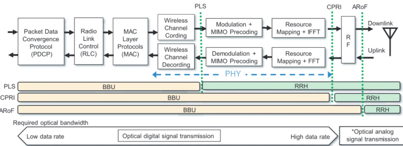
Fig. 2 Functional split points of PLS, CPRL and ARoF in C-RAN architecture.
plexing (SCM), and common public radio interface (CPRI) is presented. In Sect. 5, we comparatively analyze the de- ployment cost using the proposed framework. The paper is summarized in Sect. 6.
2. Related Works
2.1 C-RAN Architecture and Fronthaul
As shown in Fig. 2, several optical transmission technolo- gies can be used in C-RAN architecture, depending on split point of the wireless processing functions [15],[16].
Some of these architectures we considered in this study are PLS, CPRI and ARoF. In PLS, the physical layer func- tion such as modulation/demodulation, resource mapping and fast Fourier transformation (FFT) are included in the RRH[16]. In CPRI, these functions are in BBU and opti- cal link transmits analog to digital converted pure IQ data of the baseband signals. PLS and CPRI need digital sig- nal transmission. On the other hand, ARoF transmit wave- form of radio signal to/from antenna using optical analog signal transmission. Required optical bandwidths of ARoF depends on its RF carrier frequency. In ARoF each RF chan- nel needs each wavelength channels. If SCM is used the required wavelength channels can be reduced.
Recently radio access architecture and interfaces are discussed in 3GPP. Centralized configuration has been also included in a technical report of 3GPP[17]. To decrease the data rate demands of CPRI, specification of eCPRI which uses the split point in physical layer has been defined[18].
2.2 Fronthaul Networking
Wireless access using C-RAN configurations using time- division optical network (TDM-PON) have been studied to realize cost-effective implementation. TDM-PON using dy- namic bandwidth allocation (DBA) was proposed to realize low-latency, bandwidth guarantee and auto-discovery pro- cess simultaneously in [19]. A unified mobile and PON
scheduler known as Mobile-PON has been investigated to improve bandwidth-efficiency and processing-delay on up- link in[20]. Accommodatable number of ONUs in TDM- PON fronthaul using functional split was clarified in[21].
Moreover, some proposals on PON-based daisy chain networks were also reported. For example, the encapsu- lating CPRI on Ethernet with dynamic rate reconfiguration was analyzed in[22]. Long-reach PON configuration using wavelength selective asymmetrical splitters[23]and using add/drop multiplexers[24]were also reported.
3. Configuration of C-RAN Using OPGW
3.1 Overview of C-RAN Using OPGW
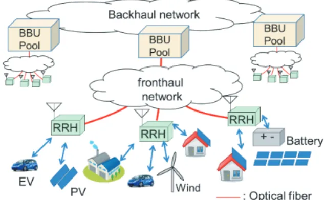
An image of architecture of C-RAN in power grids is shown in Fig. 3. Numbers of remote radio heads (RRHs) are dis- tributed using optical fronthaul network to communicate with wide spread DERs. RRHs can be simple and low cost, because functions of radio transceivers are centralized at base band unit (BBU) pools. C-RAN is one promising solution to realize low CAPEX/OPEX (capital expenditure/
operating expenditure) wireless access networks.
An image of fronthaul network using OPGWs are shown in Fig. 4. OPGWs run between the top of high- voltage transmission towers are used for point-to-point opti- cal fiber communications between power plants, substation, control center and so on. Optical fiber connection boxes are placed every 2 to 3 km in transmission line on transmission towers to extend the optical fibers in OPGWs. This periodic deployment of connection boxes is a common configuration, since the distance between connection boxes comes from the limitation of the length of one reel of OPGW. In this paper, we assumed connection boxes are placed at every 2.5 km and each of them has an RRH for simple discussion.
It is possible to drop optical fibers at these connection boxes by adding optical couplers or optical filters to connect the remote radio heads (RRHs). Transmission towers can also offer a good infrastructure to place the RRHs.
In this scenario, utilization of dark fibers in OPGW is expected. Even if all existing optical fibers are occupied, a few dark fibers could be prepared by applying wavelength division multiplexing (WDM) technique to existing opti- cal fibers communications. During the work of connection boxes, alternative path of optical fiber could be prepared to keep the required reliability and availability of the existing industrial communications as is the case with other work of inspection or replacement.
To minimize the required number of optical fibers to deploy RRHs, 3-port optical filters or optical couplers can be connected in series as shown in Fig 5. Certain wave- length channels can be dropped or added at the connection boxes by using 3-port filters. This configuration is suit- able for point-to-point connection. When optical couplers are used, optical signals are broadcasted to all RRHs. This configuration is suitable for passive optical network (PON).
Coupling ratios of the optical couplers should be carefully
Fig. 3 An image of centralized radio access network in power grid.
Fig. 4 Fronthaul network using OPGWs and transmission towers.
Table 2 Parameters for estimation of losses.
chosen to increase the number of RRHs.
3.2 Limitation of Length of Optical Fiber
•Loss of Optical Link
Estimated loss between the BBU pool and RRHs in such a configuration is shown in Fig. 6. In this analysis, loss of commercially available optical three port filters and op- tical couplers were used[25],[26]. The insertion losses of these devices and transmission loss of the optical fiber are shown in Table 2. Acceptable losses depend on loss bud- get of optical transceivers. If the loss budget is 20 dB, the scheme incorporating couplers is able to connect 10 RRHs (25 km) while the scheme with 3-port filters can connect 11 RRHs (27.5 km). The losses using 3-port filters increase lin- early with the number of RRHs. On the other hand, the losses of the last four RRHs using optical couplers were tai- lored to minimize the overall loss as different coupling ratios couplers were used in a strategic manner.
Fig. 5 Configurations of optical links using optical filters or couplers connected in series.
Fig. 6 Estimated loss from BBU pool to RRHs.
•Time out of Protocol
Since radio signals are processed at the BBU, the fron- thaul network needs to transport the signals within the re- quired time frame defined by protocol. This time limit con- fines maximum lengths of the optical fiber link since light propagation delay of 5µs/km exists. For example, the al- lowable BBU round trip processing delay and radio fre- quency (RF) processing delay will be less than a few mil- liseconds to satisfy the requirements of hybrid automatic repeat request (HARQ) used in 5G. Therefore, with a safe margin, a few hundred ofµs including the propagation delay and processing delay can be acceptable in the fronthaul. For example, if the processing time of CPRI is 100µs, RRHs can be placed within about 20 km from a BBU[13].
If time division multiplexing-PON (TDM-PON) is used as the fronthaul, the upstream delay which originates from the TDM operation (processing and queuing delay) also needs to be considered as it could significantly affect the overall delay performance. To reduce delay of TDM- PON, wireless scheduling based PON has been previously studied with an upstream delay maintained in the vicinity of 50µs[8].
•Chromatic Dispersion
It is known that chromatic dispersion of optical fiber changes intensity of received radio frequency (RF) sig- nal periodically in A-RoF when normal optical modula- tion which makes optical double sideband (ODSB) signal is used. Received RF signal intensity can be described by [27]
Fig. 7 RF signal fading in A-RoF.
Fig. 8 Location examples of BBU pools for long distance OPGWs.
P∝
cos πλ2DL f2
c +arctan(α)
!
2
(1) whereP,λ,D, L, f,candαare intensity of received RF signal, wavelength of optical carrier, chromatic dispersion value of the optical fiber, length of optical fiber, radio fre- quency, light speed and chirp parameter of optical modula- tor respectively. The value of “DL” means the cumulative chromatic dispersion of optical fiber. In this equation, loss of optical fiber is ignored for simple discussion.
Examples of calculated intensities of RF signal using f =28 and f =4.5 [GHz] are shown in Fig. 7. These two frequency bands are allocated in 5G. The chirp parameter
“α” of the optical modulation was set to 0 in these calcula- tions. Chromatic dispersion value of the optical fiber “D”
was set to 17 [ps/nm/km]. The results are profoundly af- fected by the radio frequency. The first null point appears within about 5 km when the 28 GHz RF carrier is used. On the other hand, the signal intensity is almost constant when lower frequency like 4.5 GHz is used.
The results show that ARoF using 28 GHz needs mea- sures to stabilize the RF intensity; for example, optical SSB modulation [28] or SSB filtering [29]–[31] or dispersion compensation is required. Alternatively, ARoF using inter- mediate frequency (IF) signal transmission with frequency conversion at RRH can also avoid the fading problem.
The maximum fiber length limited by loss budget and latency will typically be several tens of km, however, the maximum value is still depended on the deployment sce- nario. the length of the transmission lines sometimes spans across few hundreds of kilometers. To cover long distance OPGW, BBU-pools should be placed at the intermediate point of the transmission line if needed as shown in Fig. 8.
Table 3 Examples of required optical bandwidths for an RRH.
4. Comparison of Required Optical Bandwidth and Wavelength Channels
Required optical bandwidth and wavelength channels in these technologies are quite different as shown in Table 3.
In the calculation, 3 sector antennas, 100 MHz radio band width, 64 QAM are used. One, four and eight antennas for without MIMO, 4×4 MIMO and 8×8 MIMO are assumed.
Following Eqs. (2) and (3) introduced in[16]were used to calculate bandwidth of PLS and CPRI respectively.
BPLS =M∗Nsy∗Nsc∗Nrb∗Nmimo∗Ns/T T I (2) where, TTI is the transmission time interval, M is the highest modulation order of the radio signal,Nsyis the number of symbols within a TTI,Nscis the number of subcarrier in a resource block,Nmimois the number of MIMO streams, and Nsis the number of sector. In the calculations 1 ms, 8, 12, 12, 500, and 3 were used for TTI, M,Nsy,Nsc,NrbandNs
respectively.Nmimowere varied from 1 to 8.
BCPRI =Ns∗Na∗Sf∗Sbw∗Be∗Lc (3) where, Na is number of antennas, Sf is the sampling fre- quency,Sbwis the sampling bit-width for I/Q samples, Be is the ratio considered for the controlling overhead andLc
is the factor that accounts for the capacity increase due to 8B/10B encoding used. In the calculations, 3, 153.6 MHz, 30, 16/15, and 10/8 were used forNs, Sf,Sbw, Be, Lc re- spectively.Na=1 or 4 or 8 were used for MIMO.
CPRI based fronthaul requires 18.4, 73.7 and 147.5 Gbps for without MIMO, 4X4 MIMO and 8X8 MIMO re- spectively. These values are almost 10 times large compared with PLS. CPRI still needs higher band width though a data compression technique can reduce the required bandwidths up to 50%[32]. Moreover, CPRI always requires constant bandwidth regardless whether user traffic exists or not.
Required transport bandwidths shown as PLS in Ta- ble 3 are maximum values. Actual required bandwidths vary depending on the user traffic. Therefore, in PLS,
Fig. 9 ARoF with subcarrier multiplexing for MIMO signal transmission (multiplexing 4 channel).
cost effective 10 Gbps optical transceivers or point-to- multipoint optical fiber access technique such as time and wavelength-division-multiplexed passive optical network (TWDM-PON) can be candidates[8],[9].
ARoF requires an optical bandwidth equivalent to the radio frequency because ARoF transmits waveform of ra- dio signal directly using optical intensity modulation. If fre- quency up/down conversions are added after photodetection or before optical modulation, intermediate frequency (IF) signal transmission is also applicable. ARoF using IF signal is especially useful for millimeter-wave signal transmission to avoid expensive high-speed optical components. Based on this configuration, an RRH will typically need many wavelength channels depending on the number of MIMO antennas used in the ARoF uplink and downlink. SCM tech- nique can also be used to reduce the require optical devices by multiplexing the RF signals on a single optical wave- length channel. Such a SCM configuration can be imple- mented in ARoF as shown in Fig 9. In SCM configuration, optical modulation index M becomes small for each RF sig- nal, because maximum amplitude of the electrical input is limited. If N channels are multiplexed, the modulation index M for one RF signal becomes M/√
N[33]and the carrier- to-noise ratios (CNRs) of transmitted RF signals degrade.
Theoretical CNR degradation of SCM is calculated using (4).
C
N =10 log i2pM2 2
i2pRIN+2|e|ip+i2r B
(4) where, ip, M, RIN, e, ir, and Bare photo current, optical modulation index, relative intensity noise, charge of elec- tron, noise spectral density and radio bandwidth respec- tively.
ipcan be calculated using (5).
ip= P|e|η
νh (5)
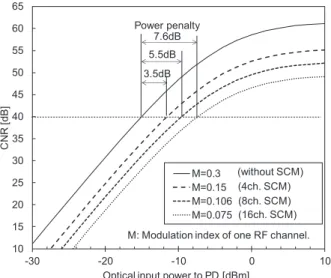
where,P,η,νandhare optical input power to the photode- tector, conversion efficiency, optical frequency and Planck’s constant, respectively. Figure 10 shows the calculated CNRs
Fig. 10 CNRs and power penalty of SCM in ARoF.
plotted as a function input optical power to the photode- tector for the cases with SCM and without SCM. The cal- culations were based on the following parameter values:
RIN = −155 [dB/Hz], |e| = 1.6 ×10⁻⁹[C], η = 0.95, B = 100 [MHz], ν = 194 [THz], h = 6.63×10⁻³⁴ and ir = 7.0 ×10⁻¹²[A/√
Hz]. The power penalties to main- tain the same CNR of 40 dB are 3.5, 5.5, 7.6 dB, when the number of multiplexed radio channel are 4, 8, 16 in SCM respectively. These values are acceptable only if the loss budgets include these power penalties. For example, for a 10 dBm optical transmitted power and 8 SCM channels, the total loss budget is calculated to be 19.5 dB, since the minimum received optical power is−9.5 dBm. Therefore, by using SCM, we can reduce the required number of op- tical wavelength channels. This also simplifies the optical wavelength channel allocation scheme. Furthermore, SCM also contributes to the simplification of RRHs by reducing the number of optical components, although we still require electrical mixers and local oscillators in the RRHs[34],[35].
5. Comparative Analysis of Deployment Cost
In this section, comparative analysis of the deployment cost of C-RAN using different optical transport technologies are shown. In this cost estimations, we used normalized cost values shown in Table 4 that are determined in previous work[13],[14],[16]. The considered architecture and the cost components we used in the analyses are also shown in Fig. 11. In the calculations, we assumed WDM con- figurations, shown in Fig. 5. One pair or multiple pairs of optical transceivers are used to connect BBU and each RRH. WDM-PON or TDM-PON technique has not been ap- plied in these calculations. If PON-technique is considered, the cost of optical transceivers in BBU can be reduced by sharing the optical transceivers placed at BBU, though the maximum optical fiber length from BBU to RAUs become shorter due to additional delays introduced by the PON tech- niques. Cost of a pair of optical transceiversγff are strongly
Table 4 Normalized cost values.
Fig. 11 Classificaton of cost components.
dependent on their bandwidth. It is assumed that the optical transceivers with 10 Gbps or 10 GHz bandwidth are used in PLS and ARoF, whilst transceivers with 40 Gbps bandwidth are used in CPRI. In ARoF without SCM, each wavelength channel needs one pair of optical transceivers. When three sectors, 8X8 MIMO is used, 24 wavelengths are needed to a single RRH. However, when using eight channels SCM, the number of required wavelength channels reduces to three.
The objective function of the framework is as follows:
minγf c
X
i∈F
ci+γf e
X
i∈N
mi+γf f
X
iN
xi
+(γri+γrr)X
i∈N
xi+γbb
X
i∈F
si+γbi
X
i∈F
zi (6)
where N is a number of locations available for the RRH de- ployment, F is a number of BBU,ci is an integer variable number of fiber connections at i th BBU,miis a binary vari- able
Fig. 12 Normalized cost varing a number of RRHs.
mi=
1; if a RRH is placed at theith connection box
0; otherwise ,
xi is an integer of number of RRHs in the i th connection box,ziis a binary variable
zi=
1; if a BBU is placed at nearith connection box
0; otherwise ,
andsiis an integer of number of BBUs installed in i th BBU.
Figure 12 shows estimated costs when numbers of RRHs are varied from 1 to 80. Since distance of each RRH is 2.5 km, 80 RRHs means 200 km length of OPGW. The costs of RRHs and fronthaul increase with the number of RRHs linearly, since the costs are proportional to number of required components. In these estimations a limitation of the fiber length between BBU and RRHs is set to 25 km, considering the discussions in Sect. 2. Intermediate BBUs,
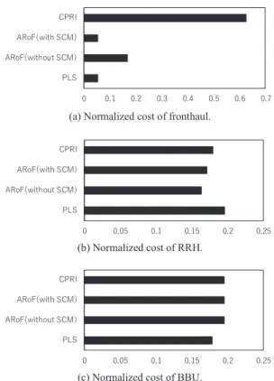
Fig. 13 Normalized cost in each component when number of RRH is 80.
as shown in Fig. 8, are expected when the length is longer than the limitation. For these reasons, the costs of BBU increase by one step at RRHs numbers of 11, 31, 51 and 71, because at the number of RRHs an intermediate BBU is added. In this configuration, cooperative operation of wire- less signal cannot be performed well when RRHs are ac- commodated in different BBUs, for example in the wireless coverage areas between #10 and #11 RRH, and between #30 and #31 RRH. This would make degradations of throughput at the edge of wireless coverage area.
Cost comparisons in each component when number of RRH is 80 are shown in Fig. 13. The comparisons show cost difference mainly comes from the fronthaul cost. In the cost of fronthaul, the costs of PLS and ARoF with SCM are the lowest deployment cost. ARoF without SCM and CPRI are about 3 times and 11 times higher than PLS or ARoF with SCM. The reason of high cost of CPRI comes from ex- pensive wide bandwidth optical transceivers. The cost dif- ference of with and without SCM comes from differences of required number of optical transceivers. In this estima- tion, the required number of optical transceivers can be one- eighth of that needed for ARoF without SCM because eight channel SCM is expected. This result shows reduction of re- quired optical bandwidth for digital signal transmission and signal multiplexing in optical analog transmission are effec- tive way to reduce the fronthaul cost. On the other hands, the cost differences in RRH and BBU are within 20% and 10% respectively. The difference is not so large.
The deployment cost of PLS and ARoF with SCM are almost the same and lower than the other considered config-
urations. It is also worthwhile to note that although cost es- timation shown in this paper include only deployment cost, in the actual network, usage fee of OPGWs might also need to be considered in some deployment scenarios. From this standpoint of OPEX, reduction of required optical fibers and wavelength channels are also required.
From these results, it can be said that PLS and ARoF configurations can support high throughput of RRHs at low cost compared to CPRI. Furthermore, SCM is an attractive technique to reduce the deployment cost of fronthaul by re- ducing the required wavelength channels when we leverage the existing resources associated with OPGW. For example, ten RRHs with three sectors using 8X8 MIMO needs 240 RF channels in ARoF. If eight channel SCM is used, re- quired number of wavelength channels become 30, which can be multiplexed on a fiber using dense wavelength divi- sion multiplexing (DWDM) technique. In ARoF, SCM is an attractive technique, because the number of fibers and wave- length channels could be limited in OPGW and coupled with the fact that it is not easy to install new fiber cables to trans- mission lines. PLS is also an attractive candidate for optical data transmission technology in C-RAN because digital sig- nal transmission is also suitable for signal multiplexing.
6. Conclusion
In this paper, optical fronthaul network using existing OPGW was investigated. From the comparative analysis of diverse optical transport technologies that can be imple- mented in OPGW to transport data of wireless network, it was found that cost-effective fronthaul could be achieved by PLS and ARoF with SCM. On the other hand, CPRI be- comes expensive because the required optical bandwidth is significantly high compared to other options. Our theoreti- cal analyses also showed that the SCM can effectively mul- tiplex several RF channels with acceptable power penalty.
In future power grids, highly reliable wireless com- munication will be indispensable. C-RAN configurations have the potential for supporting several kinds of radio transceivers at the BBU-pool simultaneously for the require- ments. The synergy of wireless communication and optical fiber communication technologies will realize a robust and resilient communication network for mission critical com- munication.
References
[1] “New services & applications with 5G ultra-reliable low latency communications,” 5G Americas. Archived from the original on April 19, 2019. Retrieved April 19, 2019. https://web.archive.org/
web/20190419231844/http://www.5gamericas.org/files/5115/4169/ 8314/5G Americas URLLLC White Paper Final 11.8.pdf, accessed on March 3, 2020.
[2] M. Ghorbanian, S.H. Dolatabadi, M. Masjedi, and P. Siano, “Com- munication in smart grids: A comprehensive review on the existing and future communication and information infrastructures,” IEEE Syst. J., vol.13, no.4, pp.4001–4014, 2019.
[3] Y. Yan, Y. Qian, H. Sharif, and D. Tipper, “A survey on smart grid communication infrastructures: Motivations, requirements, and
challenges,” IEEE Commun. Surveys Tuts., vol.15, no.1, pp.5–20, First Quarter 2013.
[4] I. Parvez, A. Rahmati, I. Guvenc, A.I. Sarwat, and H. Dai, “A survey on low latency towards 5G: RAN, core network and caching solu- tions,” IEEE Commun. Surveys Tuts., vol.20, no.4, pp.3098–3130, Fourth Quarter 2018.
[5] A. Hassebo, A.A. Mohamed, R. Dorsinville, and M.A. Ali, “5G- based converged electric power grid and ICT infrastructure,” 2018 IEEE 5G world forum (5GWF), pp.33–37, 2018.
[6] B. Leonard, Connecting America: The National Broadband Plan, Diane publishing, p.251, 2010.
[7] N.J. Gomes, P.P. Monteiro, A. Gameiro, Next Generation Wireless Communications Using Radio over Fiber, John Wiley & Sons, 2012.
[8] Y. Nakayama and D. Hisano, “Wavelength and bandwidth alloca- tion for mobile fronthaul in TWDM-PON,” IEEE Trans. Commun., vol.67, no.11, pp.7642–7655, 2019.
[9] K. Miyamoto, S. Kuwano, J. Terada, and A. Otaka, “Analysis of mobile fronthaul bandwidth and wireless transmission performance in split-PHY processing architecture,” Opt. Express, vol.24, no.2, pp.1261–1268, 2016.
[10] Next Generation Mobile Networks Alliance, Frankfurt, Germany,
“Further study on critical CRAN technologies,” White Paper, 2015.
[Online]. Available: https://www.ngmn.org
[11] A. Checko, H.L. Cheristinasen, Y. Yan, L. Scolari, G. Kardaras, M.
Berger, and L. Dittmann, “Cloud RAN for mobile networks — A technology overview,” IEEE Commun. Surveys Tuts., vol.17, no.1, pp.405–426, 2015.
[12] D. Waka, A. Nkansah, and N.J. Gomes, “Radio over fiber link design for next generation wireless systems,” J. Lightw. Technol., vol.28, no.16, pp.2456–2464, 2010.
[13] C. Ranaweera, E. Wong, A. Nirmalathas, C. Jayasundara, and C.
Lim, “5G C-RAN with optical fronthaul: An analysis from a de- ployment perspective,” J. Lightw. Technol., vol.36, no.11, pp.2059–
2068, 2018.
[14] K. Ikeda, C. Lim, A. Nirmalathas, and C. Ranaweera, “A comparison of optical transport technologies for wireless communications using optical ground wire in smart grid,” 7th International conference on smart grid (icSmartGrid), pp.74–80, 2019.
[15] C. Ranaweera, P. Monti, B. Skubic, E. Wong, M. Furdek, L.
Wosinska, C. Mas Machuca, A. Nirmalathas, and C. Lim, “Optical transport network design for 5G fixed wireless access,” J. Lightw.
Technol., vol.37, no.16, pp.3893–3901, 2019.
[16] C. Ranaweera, E. Wong, A. Nirmalathas, C. Jayasundara, and C.
Lim “5G C-RAN archtecture: A comparison of multiple optical fronthaul networks,” International conference on optical network de- sign and modeling (ONDM), pp.1–6, 2017.
[17] 3GPP, “Study on new radio access technology; radio access architec- ture and interfaces (Release 14),” TR 38.801, v2.0.0, March 2017.
[18] eCPRI, “eCPRI specification,” Available: https://protect-au.mime cast.com/s/R0vKCMwvygsq0PoBvIQ6hkO?domain=cpri.info, ac- cessed on March 3, 2020.
[19] H. Uzawa, K. Honda, H. Nakamura, Y. Hirano, K. Nakura, S.
Kozaki, and J. Terada, “Dynamic bandwidth allocation scheme for network-slicing-based TDM-PON toward the beyond-5G era,” J.
Opt. Commun. Netw., vol.12, no.2, pp.A135–A143, 2020.
[20] S. Zhou, X.g Liu, F. Effenberger, and J. Chao, “Low-latency high- efficiency mobile fronthaul with TDM-PON (Mobile-PON),” J. Opt.
Commun. Netw., vol.10, no.1, pp.A20–A26, 2018.
[21] D. Hisano, H. Uzawa, Y. Nakayama, K. Miyamoto, J. Terada, and A. Otaka, “Clarification of accommodatable number of functional split base stations in TDM-PON fronthaul,” IEICE Communications Express, vol.7, no.5, pp.160–166, Feb. 2018.
[22] L. Valcarenghi, K. Kondepu, and P. Castoldi, “Analytical and ex- perimental evaluation of CPRI over Ethernet dynamic rate reconfig- uration,” 2016 IEEE International Conference on Communications (ICC), pp.1–6, Kuala Lumpur, Malaysia, 2016.
[23] A. Kawakita, K. Hara, and Y. Kimura, “Design for long-reach coex-
isting PON in consideration of area characteristics with wavelength selective asymmetrical splitters,” 2019 24th OptoElectronics and Communications Conference (OECC) and 2019 International Con- ference on Photonics in Switching and Computing (PSC), TuA3-4, Fukuoka, Japan, 2019.
[24] M. Kagawa, H. Tsukada, and M. Yoneda, “Optical add-drop multi- plexers for metro/access networks,” Furukawa review, no.23, pp.59–
64, 2013. https://www.furukawa.co.jp/review/fr023/fr23 12.pdf, ac- cessed on March 3, 2020.
[25] Hikari, inc. HP, “3-Port TFF Device,” http://www.hikari-trading.
com/opt/accelink/0017.htm, accessed on Dec. 28, 2019.
[26] Thorlabs, Inc. HP, “1550 nm 1x2 Single Mode Fused Fiber Optic Couplers/Taps,” https://www.thorlabs.com/newgrouppage9.cfm?ob jectgroup id=9567, accessed on March 3, 2020.
[27] F. Devaux, Y. Sorel, and J.F. Kerdiles, “Simple measurement of fiber dispersion and of chirp parameter of intensity modulated light emitter,” IEEE/OSA J. Lightwave Technol., vol.11, no.12, pp.1937–
1940, Dec. 1993.
[28] G.H. Smith and D. Novak, “Broad-band millimeter-wave (38 GHz) fiber-wireless transmission system using electrical and optical SSB modulation to overcome dispersion effects,” IEEE Photon. Technol.
Lett., vol.10, no.1, pp.141–143, 1998.
[29] K. Kitayama, “Fading-free transport of 60 GHz-optical DSB sig- nal in non dispersion shifted fiber using chirped fiber grating,”
Proc. IEEE Int. Topical Meeting on Microwave Photonics 1998 (MWP1998), WB4, 1998,
[30] K. Kitayama, T. Kuri, K. Onohara, T. Kamisaka, and K. Murashima,
“Dispersion effects of FBG filter and optical SSB filtering in DWDM millimeter-wave fiber-radio systems,” IEEE/OSA J. Lightw. Tech- nol., vol.20, no.8, pp.1397–1407, 2002.
[31] H.H. Lu, W.S. Tsai, H.C. Peng, and Y.J. Ji, “A comparison between optical SSB transmitter-filter in a full-duplex radio-on-fiber trans- port system,” IEEE Commun. Lett., vol.9, no.7, pp.649–651, 2005.
[32] B. Guo, W. Cao, A. Tao, and D. Samardzija “LTE/LTE-A signal compression on the CPRI interface,” Bell Labs Tech. J., vol.18, no.2, pp.117–133, 2013.
[33] M. Maeda, K. Haeiwa, and Y. Toba, Fundamentals and their Appli- cations of Radio on Fiber Technologies, Corona publishing, pp.7–
15, 2013 (in Japanese).
[34] L. Giorgi, G. Bruno, J. Nijhof, P.J. Urban, G. Vall-llosera, F. Ponzini, and J. Ladvanszky, “Subcarrier multiplexing RF plans for analog radio over fiber in heterogeneous networks,” J. Lightw. Technol., vol.34, no.16, pp.3859–3866, 2016.
[35] P. Assimakopoulos, A. Nkansah, N. Gomes, and D. Wake, “Multi- channel signal transmission through radio over fiber architecture,”
2011 IEEE GLOBECOM Workshops, pp.152–156, 2011.
Kensuke Ikeda received the B.E., M.E., and Ph.D. degrees in communications engineering from Osaka University, Osaka, Japan, in 2001, 2003, and 2006, respectively. He joined Cen- tral Research Institute of Electric Power Indus- try (CRIEPI), in 2006, where he has been work- ing on radio-on-fiber system and communica- tion systems for smart grid. In 2019–2020, he was a visiting researcher at the University of Melbourne. He is a member of IEICE, IEEE and the institute of electrical engineers of Japan (IEEJ).
Christina Lim received B.E. and Ph.D.
degrees in electrical and electronic engineering from the University of Melbourne, Australia, in 1995 and 2000, respectively She is a Professor at the Department of Electrical and Electronic Engineering, the University of Melbourne, Aus- tralia. Her research interests include fiber- wireless access technology, free-space com- munications, modeling of optical and wireless communication systems, microwave photonics, electro-optic sampling techniques and optical network architectures. She is a Senior Member of IEEE, a Fellow of The Optical Society (OSA).
Ampalavanapillai Nirmalathas received B.Eng and Ph.D. degrees in electrical and elec- tronic engineering from the University of Mel- bourne in 1993 and 1998, respectively. He is a Professor of Electrical and Electronic Engineering at the University of Melbourne, Australia. His current research interests in- clude energy-efficient telecommunications, ac- cess networks, optical–wireless network inte- gration, and broadband systems and devices. He is a Senior Member of IEEE, a member of The Optical Society (OSA), and a Fellow of the Institution of Engineers Aus- tralia.
Chathurika Ranaweer received the B.Sc.
and Ph.D. degrees in electrical and electronic engineering from The University of Peradeniya, Sri Lanka and The University of Melbourne, Australia, respectively. She is currently a senior lecturer at Deakin University, Melbourne, Aus- tralia. Her research interests include, optical- wireless convergence, optical transport network architectures, IoT connectivity, energy-efficient communications and networks, network opti- mization, quality of service management, Smart grid communication and machine learning applications in networking.