PAPER Special Section on Circuits and Systems
Active Vibration Control of Nonlinear 2DOF Mechanical Systems via IDA-PBC
Sheng HAO†a),Nonmember, Yuh YAMASHITA†,andKoichi KOBAYASHI†,Members
SUMMARY This paper proposes an active vibration-suppression con- trol method for the systems with multiple disturbances using only the relative displacements and velocities. The controller can suppress the vibration of the main body in the world coordinate, where a velocity disturbance and a force disturbance affect the system simultaneously. The added device plays a similar role as an accelerometer, but we avoid the algebraic loop.
The main idea of the feedback law is to convert a nonlinear system into an aseismatic desired system by using the energy shaping technique. A parameter selection procedure is derived by combining the constraints of nonlinear IDA-PBC and the evaluation of the control performance of the linearly approximated system. The effectiveness of the proposed method is confirmed by simulations for an example.
key words: nonlinear control, vibration measurement, sensors
1. Introduction
Vibration suppression is a basic problem in the design of mechanical systems, and active vibration suppression meth- ods have been used in actual mechanical systems for some decades. From the viewpoint of vibration suppression ef- fect, active vibration control can give us much better vi- bration suppression performance than passive methods[1].
Unfortunately, most of active vibration control methods are based on the assumption that all the states are exactly known [2]–[6]. If the state is the relative information with refer- ence plane, it will be easy to be observed by sensors. On the other hand, if the reference plane is vibrating, it is diffi- cult to observe the absolute position and velocity directly by inexpensive sensors.
Although it is possible to observe the absolute informa- tion by the development of sensor technology, it should be pointed out that there are some problems such as expensive equipment and limited-frequency characteristics. We can use cheap MEMS accelerometers nowadays, and the meth- ods using an accelerometer to obtain absolute information are developed[7], whereas they will result in the generation of an algebraic loop, and such methods are difficult to be applied in nonlinear cases. The methods using observer can estimate the absolute information[8], but those methods are also difficult to be applied in nonlinear case and it is essen- tial to remember that they typically lead to a degradation in performance.
In automobile industry, many works on the suspension Manuscript received November 27, 2019.
Manuscript revised March 23, 2020.
†The authors are with the Faculty of Information Science and Technology, Hokkaido University, Sapporo-shi, 060-0814 Japan.
a) E-mail: [email protected] DOI: 10.1587/transfun.2019KEP0007
design using robust control method against the unmeasured external vibration have been developed during the last two decades. The robust controller can be designed by Linear- Quadratic-Gaussian (LQG) methodology[8],H∞technique [9],[10], saturated adaptive robust control (ARC) strategy [11]and so on. Especially, the works based onH∞technique show good performance on the robustness with respect to the uncertainties due to sensors. Even so, in order to apply these methods to nonlinear systems, we often need to solve Hamilton-Jacobi equations.
Motivated by aforementioned issues, Aoki et al. [12]
proposed a method that sets a device similar to tuned mass damper (TMD)[13]on the controlled object and utilizes in- terconnection and damping assignment passivity-based con- trol (IDA-PBC) method[14], which is a very general energy shaping control method, to gain the ideal vibration suppres- sion performance. In that research, Aoki et.al use the device like an accelerometer, but they considered its dynamics so that the algebraic loop is avoided. They use IDA-PBC to con- vert the controlled system to the system with skyhook damper [5]. Although Aoki et al.[12]were successful in suppress- ing the vibration only with relative displacement and velocity and without any accelerometer signal, the method only han- dles the linear case and simple nonlinear-spring case.
In this paper, we obtain an IDA-PBC vibration suppres- sion controller for more general port Hamiltonian systems.
We first identify a class of port Hamiltonian systems with force and velocity disturbances, which is a general system expression for the cases with a floating nonlinear mechani- cal structure with additional spring and damper. We show a control law including some free parameters with some con- straints. The controller uses only relative information, which can be easily measured. We propose a new parameter de- sign method, which is more accomplished than that of[12].
The parameter selection can be made constructively. Finally, we show an example with simulation results, which verify the good vibration effect of the proposed controller. The stability of the nonlinear closed-loop system is guaranteed theoretically by the IDA-PBC method.
Compared to the preliminary study[15]of this research, the parameter design method in this paper is more sophisti- cated than that in[15]. With this new method, the parameter design become flexible. Moreover, we expect that the param- eter design that is robust against the parameter uncertainties becomes possible by the new scheme, and it is our future work.
Copyright © 2020 The Institute of Electronics, Information and Communication Engineers
Fig. 1 Conventional vibration suppression method.
2. Motivation of the Proposed Method
Let us consider a simple linear structure like Fig. 1(a), where u, F, k,cand z denote feedback input, force disturbance, elastic coefficient of the spring, damping coefficient, and dis- placement of the floor, respectively. If we know the absolute displacement of the main body, it is easy to suppress the vi- bration through active vibration control methods. One of the most commonly applied method is skyhook damper method, where the input force works as a virtual damper that is set between main body and rigid ceiling as showed in Fig. 1(b).
With this method, we can realize ideal control performance.
However, the reference point of the absolute position is lost due to the floor vibration, making it difficult to obtain the absolute information of the main body which is required for the skyhook damper method.
We can obtain the absolute information indirectly via an accelerometer. A direct feedback of the acceleration sig- nal causes a static loop, and integration of the acceleration signal to obtain the velocity causes a drift problem. Fil- tering techniques may solve the static-loop problem, but a frequency-domain design is often required due to undesired phase-lag of the filter, which cannot be applied to nonlinear systems.
Therefore, in this paper we propose a new vibration- suppression control that utilizes only relative informations.
To obtain more rich information from the measurements of the relative movements, we assume that there exists an additional mechanical degree-of-freedom (DOF) in the con- trolled object. This approach is almost equivalent to consid- ering the internal dynamics of an accelerometer precisely.
In addition to the cases with accelerometers, our method can be applied to the systems in which additional (nonlinear) dynamic structure is naturally contained. In these cases, the additional structure may have a mass that cannot be ignored, and the motion the additional structure has a phase lag even for the low frequncy range.
3. Controlled Object and Problem Setting
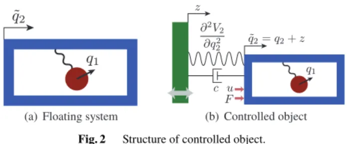
In this section, we specify a class of port Hamiltonian sys- tems with force and velocity disturbances, which commonly appear in vibration suppression problem. In our research, we set a nonlinear additional mass on the main body as shown in Fig. 2(a), where q1 denote the relative displacement of the additional mass and ˜q2 denote the displacement of the main body in world coordinate. The system is a part of a
Fig. 2 Structure of controlled object.
controlled object, but is not the target system itself.
We assume that there exists a symmetry on the change of ˜q2, which derives a law of conservation of momentum with respect to the movement of the whole mass to ˜q2 direction by the Noether’s theorem[16]. According to the symmetry, the Hamiltonian of this system is not the function of ˜q2, i.e.
the inertia matrix and the potential energy only depend on q1. Consequently, the Hamiltonian of the system of Fig. 2(a) can be written as
H(q˜ 1,p)=1
2p>M(q1)−1p+V1(q1) M(q1)=
"
m1(q1) m2(q1) m2(q1) m3(q1)
# (1)
p=M(q1) q˙1
˙˜
q2
!
, (2)
and the friction coefficient matrix becomes ˜C=diag(µ,0), where µ > 0 is the friction coefficient of the additional movement. The positive-definite matrix M(q1) is the in- ertia matrix, V1(q1) is the potential energy of the internal structure, and p is the generalized momentum. We as- sume thatV1(q1)is positive definite with respect toq1. The law of conservation of momentum of the basic structure is p2 = m2(q1)q˙1 +m3(q1)q˙˜2 =const.We assume that there exists an interconnection between the motion of q1 and ˜q2, and thusm2(q1),0.
By adding a potential forceV2(q2)and a damping term cq˙2with respect to the relative movement between the main body and a vibrating object, a force disturbance F, and a control inputu, we obatin the controlled object like Fig. 2(b).
We assume that the control force and the force disturbance act on the main body. The Hamiltonian of the controlled system is
H(p,q)=H˜(q1,p)+V2(q2)
q=(q1,q2)>, q2 =q˜2−z(t), (3) where z and q2 denote the displacement of the vibrating object and the relative displacement of main body from the object, respectively. We let the additional potentialV2(q2) be positive definite with respect toq2as well. The definition (2) ofpcan be rewritten as
p=M(q1) q˙−aω, (4) whereω = z˙is a velocity disturbance, and a = (0,−1)>. Notice thatpis defined in the world coordinate, whileqis a
relative displacement vector.
Thus, the controlled object can be expressed by a port- Hamiltonian system (PH system)
˙
x=(J−R)∂H
∂x
>
+Dω+B(u+F), (5) wherex=(q>,p>)>is the state, and
J=
"
O I
−I O
# , R=
"
O O O C
#
, C=C˜+C˜a=
"
µ 0
0 c
# ,
B=(0 0 0 1)>,
D=(a> −(Ca)>)>=(0 −1 0c)>.
Our main purpose is the vibration suppression of ˜q2 against the velocity disturbance ω(t) and the force distur- banceF(t). Note that ˜q2 ≈0 meansq2 ≈ −z(t). Since the second element ofDis−1, a feedforward term ofωexists in the dynamics ofq2, and therefore suppression of pwill achieve the control objective. In this study, we construct an IDA passivity-based controller using only the relative dis- placementsqand velocities ˙q, which can be easily measured by sensors. Note that our control law is not a function ofq andpbutqand ˙q, becausepis defined in the world coordi- nate and (4) includesω.
4. Application of IDA-PBC
4.1 Overview
In this section, we define the dynamics of desired system at first, and then obain a matching condition between the controlled system and the desired system. The matching condition clearfy the degree of freedom in the controller de- sign and the expression of feedback law with free parameters as well as equality and inequality constraints.
4.2 Desired System
We construct the desired system with artificial strucutre ma- trix as follows:
˙
x=(Jd(q1)−Rd(q1))∂Hd
∂x
>
+Dd(q1)ω +Dd p(q1)p·ω+Ddω(q1)ω2+BF,
(6) where
Hd(x)=1
2p>Md(q1)−1p+Vd(q1,q2) (7) denotes the Hamiltonian of desired system, and
Md(q1)=
"
md1(q1) md2(q1) md2(q1) md3(q1)
# , Jd(q1)=
"
O M(q1)−1Md(q1)
−Md(q1)M(q1)−1 J2(q1)
# , J2(q1)=
"
0 je(q1)
−je(q1) 0
# ,
Rd(q1)=
"
O O
O Cd(q1)
#
, Cd(q1)=
"
cd1(q1) cd2(q1) cd2(q1) cd3(q1)
# , Dd(q1)=(0 −1 0d1(q1))>,
Dd p(q1)=
"
0 0 0 d2(q1) 0 0 0 d3(q1)
#>
, Ddω(q1)=(0 0 0d4(q1))>.
Jd(q1),Rd(q1),Vd(q), andMd(q1)denote an artificial skew- symmetric structure matrix, a positive semidefinite damping matrix, a potential energy, and the inertia matrix in the de- sired Hamiltonian, respectively.
4.3 Application of IDA-PBC Method
We can derive the expression of feedback law with equality and inequality constraints on the parameters of the desired system by matching the dynamics of desired system with that of controlled system as follows:
(Jd−Rd)∂Hd
∂x
>
=(J−R)∂H
∂x
>
+Bu
+(D−Dd)ω−Dd p(q1)p·ω−Ddω(q1)ω2. (8) For convenience of calculations, we set
S(q1)=M−1(q1)=
"
s1(q1) s2(q1) s2(q1) s3(q1)
#
Sd(q1)=Md−1(q1)=
"
sd1(q1) sd2(q1) sd2(q1) sd3(q1)
# .
(9)
Hereafter, by omitting ‘(q1)’, we simply express them asS, Sd,si andsdi. Each side of (8) is four dimensional vector.
The first two components of (8) are already satisfied for all x andω. We can easily derive the equality constraints of parameters by extracting the coefficients of p, q and thier higher-order terms. By focusing on the coefficients of p21, p1p2andp22in the third component of (8), we obtain
sd10= |Sd|s10 s1sd3−s2sd2 sd20= |Sd|s20
s1sd3−s2sd2
sd30= |Sd|s30
s1sd3−s2sd2,
(10)
where∗0means the derivative with respect toq1.
The coefficients ofp1andp2in the third component of (8) derive the following relations:
cd1(q1)= µ
|Sd|(s1sd3−s2sd2) (11) je(q1)=cd2(q1)+ µ
|Sd|(s1sd2−s2sd1). (12) The rest of the third component of (8) leads an equation for the potential energy
s2sd2−s1sd3
|Sd| ·∂Vd
∂q1 +s3sd2−s2sd3
|Sd| ·∂Vd
∂q2 +V10=0.
The general solution of the above equation is Vd(q)=P
q2+Z q1 0
s3sd2−s2sd3 s1sd3−s2sd2
q1=τ
dτ
+Z q1
0
V10|Sd| s1sd3−s2sd2
q1=τ
dτ,
(13)
wherePwill be an arbitrary positive-definite function.
By solving the forth equation of (8) with respect tou, we can obtain a feedback lawu=αraw(q,p, ω). Notice that the feedback should be a function ofqand ˙q only. Hence, we decomposeαrawas
αraw q,M(q1)(q˙−aω), ω =α(q,q)˙ +αrest(q,q, ω)ω.˙ The coefficientαrest(·)should be identically zero, and thus we decompose it again as
αrest(q,S(q1)p+aω, ω)=
α1(q1)+α2(q1)p1+α3(q1)p2+α4(q1)ω.
By solving αi(q1) = 0 (i = 1, . . . ,4)with respect to d1(q1), . . . ,d4(q1)and applying (10), we obtain additional equality constraints
d1(q1)= 1
|S|{(s1sd3−s2sd2)cd3(q1) +(s1sd2−s2sd1)(je(q1)+cd2(q1)}
(14) (d2(q1)d3(q1))=g(q1)·(0 1)M0S (15) d4(q1)=g(q1)
2 ·(0 1)M0(0 1)>, (16)
whereM0=∂M/∂q1and g(q1)= s2sd1−s1sd2
s1sd3−s2sd2. The control input can be written as
u=α(q,q)˙
= (s2sd3−s3sd2)cd3−(s3sd1−s2sd2)(cd2+je)
|S| q˙1
+(c−d1(q1))q˙2+g(q1)
2 ·q˙>M0q˙+∂V2(q2)
∂q2
+s1sd2−s2sd1
|Sd| ·∂Vd
∂q1 −s3sd1−s2sd2
|Sd| ·∂Vd
∂q2. (17) Because of the feature of IDA-PBC, the closed-loop system is identical to the desired system. Therefore, the asymptotic stability of zero-disturbance case can be guaranteed by the nature of port-Hamiltonian system. Thus we need to ensure the positive definiteness ofMd,VdandCd, and the following inequality constraints can be derived:
sd3(q1)>0, |Sd(q1)|>0, (18)
s1sd3−s2sd2 >0, ∀q1, (19)
|Cd(q1)| >0, (20)
P[σ]>0, σ,0. (21)
Inequalities (18) show the positive definiteness of the inertia matrix of the desired system. We can show cd1(q1) > 0 from (19) and (11), and therefore (19) and (20) means that the damping matrix of the desired system is positive definite.
Because of (19), the positivity of the second term of (13) will be automatically satisfied if q1V10 ≥ 0. Hence, under the constraint (21), the potential energy function Vd(q) is positive definite.
We can gainsdi(q1)by solving (10), while the initial value Sd(0) =Sd0 is a degree of freedom. The inequality constraints of parameters are (18), (19), (20), and (21). The equality constraints of parameters are (11), (12), (13), (14), (15), (16), and (17).
Note that the asymtotic satbility is guaranteed by the positive definiteness ofMd,VdandCd. Therefore, stability of the numerical solution process of differential equation (10) is not required when desgining the control law.
In next section, we derive the guideline of parameter selection in order that we can obtain an aseismatic desired system.
5. Guideline for Parameter Selection
5.1 Linear Approximation
To design the parameters of desired system, we need to know what role the each parameters play in vibration dynamics.
However, because of the nonlinear term, the pratical meaning of parameters in inertia matrix is unclear. Hence, we will derive the guideline of the parameter selection based on the linearly approximated systems of (5) and (6) at first, which determines the low-order terms of the free parameters.
Then we will apply it into nonlinear case. By the quadratic approximation ofH, the Hamiltonian of the linearized plant is
HL(p,q)=1
2p>S0p+1
2(K1q12+K2q22), where
S0=
"
s10 s20 s20 s30
#
=S(0) K1= ∂2V1
∂q21 (0), K2= ∂2V2
∂q22 (0).
The linearized controlled object can be described as
˙ x=
"
0 I
−I −C
# diag(K1,K2)q S0p
! + a
−Ca
!
ω. (22)
The quadratic approximation ofHdcan be also obtained as HdL(p,q)=1
2{p>Sd0p+Kd1q12+Kd2(q2+hq1)2},
where Sd0 =
"
sd10 sd20 sd20 sd30
#
=Sd(0), h= s30sd20−s20sd30
s10sd30−s20sd20
(23) Kd1 = K1|Sd0|
s10sd30−s20sd20, Kd2= ∂2P(y0)
∂ y02
y0=0
. (24) The linearized desired system is
˙
x=(Jd0−Rd0) Kd0q Sd0p
!
+Dw0ω+BF, (25) where
Jd0=
"
O M0−1Md0
−Md0M0−1 J20
# , J20=
"
0 je0
−je0 0
#
Md0 =Sd0−1=
"
md1 md2 md2 md3
#
,Kd0=diag(Kd1,Kd2) Rd0 =
"
O O
O Cd0
#
, Cd0 =
"
cd10 cd20
cd20 cd30
#
Dw0 =(0 −1 0d10)>
5.2 Coordinate Transformation
The diagnolized inertia matrix can help us clarify the struc- ture of linearized system, thus we consider new transformed variables
ˆ
q=L−1q, pˆ=L>p, (26) where
L=
"
r0 −r0
0 1
#
, (27)
r0= m20 m10 =−s20
s30
. (28)
To simplify the problem, we chooseSd0such thathdefined by (23) becomes zero, i.e.
s20 s30 = sd20
sd30
. (29)
Under the new constraint (29), r0= md20
md10 =−sd20 sd30
is also satisfied as well as (28).
The coordinate of main mass q2 is maintained with this coordinate transformation, i.e. ˆq2 = q2. Please recall that the control objective is the vibration suppression of the main body. Then, the linear approximation of (4) can be transformed to
ˆ
p=L>M0L(q˙ˆ−L−1L>aω)=Mˆ(q˙ˆ−aω),ˆ
where
Mˆ =L>M0L=diag.(mˆ1,mˆ2) ˆ
m1 =m10r02, mˆ2=m30−m10r02 ˆ
a=L−1L>a=(−1 −1)>.
Consequently, the linearized controlled object (22) can be transformed to
˙ˆ q
˙ˆ p
!
=
"
0 I
−I −Cˆ
# Kˆqˆ
Sˆpˆ
! + aˆ
−Cˆaˆ
!
ω, (30)
where
Sˆ=Mˆ−1=diag(mˆ−11 ,mˆ−12 ) Kˆ =LTdiag(K1,K2)L=
"
Kˆ1 −Kˆ1
−Kˆ1 Kˆ1+Kˆ2
#
Cˆ=LTC L=
"
Cˆ1 −Cˆ1
−Cˆ1 Cˆ1+Cˆ2
#
Kˆ1=K1r20, Kˆ2=K2, Cˆ1 =µr20, Cˆ2=c.
Under the assumption (29), the inertia matrix of the linearized desired system (25) in the new coordinate is
Mˆd=L>Md0L=diag(mˆd1,mˆd2)
=diag(md10r02,md30−md10r02),
which is also a diagonal matrix under the constraint of (29).
The linearized desired system is also converted into
˙ˆ q
˙ˆ p
!
=(Jˆd−Rˆd) Kˆdqˆ Sˆdpˆ
!
+Dˆdω+BF,ˆ (31) where
Jˆd=
"
O Mˆ−1Mˆd
−MˆdMˆ−1 Jˆ2
#
, Jˆ2 =LTJ20L, Sˆd =Mˆd−1=diag(mˆ−1d1,mˆ−1d2),
Kˆd =LT
"
Kd1 0 0 Kd2
# L=
" Kˆd1 −Kˆd1
−Kˆd1 Kˆd1+Kˆd2
# , Kˆd1=Kd1r02, Kˆd2=Kd2,
Rˆd =diag(O,Cˆd), Cˆd =LTCd0L=
"Cˆd1+Cˆd2 −Cˆd2
−Cˆd2 Cˆd2+Cˆd3+Cˆd4
# , Cˆd1=r0cd2, Cˆd2=r20cd10−r0cd2,
Cˆd3=cd30−r0cd20−d10, Cˆd4=d10, Dˆd =diag(L−1,LT)Dw0=(−1 −1 0d10)>, Bˆ=diag(L−1,LT)B=B.
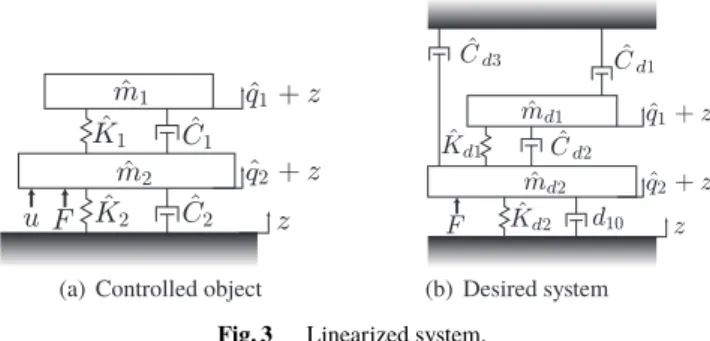
The linearized controlled object (30) can be considered as a mass-spring-damper (MSD) system with a device similar to tuned mass damper (TMD) in Fig. 3(a). When we ignore the difference between Jand ˆJd, the linearized desired sys- tem (31) is regarded as an MSD system with a TMD-like
Fig. 3 Linearized system.
device and multiple skyhook dampers in Fig. 3(b). Thus, in linearized case, the feedback law in this research realizes the virtual skyhook dampers by only relative displacements and velocities.
5.3 Parameter Design We define mass ratios
r1= mˆd1
ˆ
m1 = md10
m10, r2= mˆd2
ˆ
m2 . (32)
The valuesr1andr2are positive, if and only ifSd0>0.
From the definition (32), the inequality constraint (20) can be rewritten as
|Cd0|=µd10r1r2−cd20−µr0(r1−r2)2>0. (33) From the view point of energy, the small dissipation matrix is unsuitable for the control objective. Thus we setcd20as
cd20=µr0(r1−r2), (34) which maximizes|Cd0|for fixedr1andr2. Hence, positive r1, r2, and d10 make Cd0 and Md0 positive definite, and the asymptotical stability of the linearized desired system is guaranteed. We will designd10,r1, andr2such that|Cd0|is sufficiently large, under the new constraint (34).
Under the assumptions (29) and (34), we obtain cd30=r2d10+ µr02(r2−r1)2
r1 . (35)
The value of skyhook-damper coefficient of the mainbody becomes
Cˆd3=d10(r2−1)+ µr20r2(r2−r1) r1
. (36)
Obviously, large d10, r2 and small r1 can make skyhook damper coefficient (36) be large. However, large d10 will lead to the increasement of the high frequency gain fromz toq2, bacaused10indicates the damping coefficient between the vibrating object and the main body, as seen in Fig. 3(b).
Hence, we choose small d10 first, and design small r1 and large r2 so that skyhook damper term coefficient Cˆd3 is sufficiently large, because of (36). From empirical knowledges, smalld10and large ˆCd3in Fig. 3(b) make a good
vibration suppression effect.
The selection (34) makes ˆCd1, which is the coefficient of the skyhook damper of the additional mass in Fig. 3(b), negative, but|Cd0|>0 is guaranteed by a largecd30. A large r2also decreases the low-frequency gain fromFas
GFq˜2(0)= Kd2 r2
. (37)
The above parameter selection guideline is more so- phisticated than that in Aoki, et al. [12]. The parameter selection procedure is summarized as follows.
1. Choose sufficiently smalld10 > 0, sufficiently small r1 > 0, and sufficiently larger2 > 0. Select a small low-frequency gain with r2 and Kd2 in (37). Then design a positive-definite functionP[·] by (24). From (29) and (32),Sd0(>0) is determined.
2. CalculateSd(q1) by solving the differential equations (10) with the initial conditionSd(0)=Sd0.
3. Check the conditions (18) and (19). If these inequalities are not satisfied for allq1, return to the first step and choose the parameters again.
4. Setcd1(q1)as (11). The values ofcd2(0) = cd20and cd3(0)=cd30are determined by (34) and (35), respec- tively, and thenCd0=Cd(0)>0 is guaranteed. Choose the high-order terms ofcd2(q1)andcd3(q1)adequately so thatCd(q1)>0.
5. Calculate je(q1),Vd(q), andd1(q1)by (12), (13), and (14), respectively.
6. Obtain the control law (17).
Although the design procedure is constructive, the high- order terms of cd2 and cd3 should be chosen to satisfy Cd(q1) > 0. Along with the increasing of q1, the prac- tical meaning of inertia matrix in desired system will be far different from that of linear approximated case. There- fore,Cd(q1) far from the origin must be varied along with changes of the inertia matrix. On the other way, large |q1| often means that the current vibration is violent, hence it is natural to make the feedback gain high when|q1|reaches a threshold. The idea of control barrier function may be uti- lized for this purpose, but this topic is one of our future work.
In this paper, the parameter selection guideline is focusing on making the skyhook damper term large, while the free parameter selection in this proposed method can control not only the skyhook damper term but also the mass and spring term. The problem of how to adjust those terms to suppress the vibration in a wider frequency domain will depend on the sensitivity from the free-parameter selection to the control performance, and that is also our future work.
6. An Example and Simulation
In this section, in order to verify the vibration suppression effect of the proposed feedback law (17), we will construct a control system for an example and make simulations for the system.
We consider a main body (cart) with a pendulum like
Fig. 4 Cart and pendulum system.
Fig. 4, where mp, mc,l, c, µ, and K2 denote mass of the pendulum, mass of the cart, length of massless bar, viscosity dumper coefficient between the cart and the vibrating wall, rotational friction coefficient at the axis of the pendulum, and elastic coefficient between the cart and the vibrating wall, respectively. We choose the variables q1, ˜q2, z, F, anduas swing angle of the pendulum, displacement of the cart in world coordinate, displacement disturbance of the basement, force disturbance on main body, and input force, respectively. Here we set the parameters of controlled object asmp =0.2,mc =10,l =5,c=2, µ=10, andK2 =3.
The disturbances are z = sin(bt) andF =100 cos(bt) for b=1 andb=10.
To verify the performance of the proposed method, we perform simulations for the open loop system, the closed- loop system using the proposed feedback law, and the closed- loop system using conventional method which is skyhook damper method. We consider the skyhook damper feedback law
u=−Cˆd3q˙˜2,
where ˆCd3is the same value as the desired skyhook damper used in our proposed method. However, we apply the sky- hook damper method with the assumption that absolute dis- placement and velocity of the cart are measurable, while our proposed method only uses relative displacement and velocity information.
According to the proposed guideline of parameter se- lection in section 5, we firstly setting smalld10, samllr1and larger2 asd10 =2,r1 =15 andr2 =1000. Since a small low-frequency gainGFq˜2(0)is preferred, we design the part of the desired potential energy fucntionP[·] asP[γ]=5γ2, so thatGFq˜2(0) = 0.005. By setting cd2(q1) = cd20 and cd3(q1)=cd30, we can ensure that the inequality constraints (18), (19) and (20) are satisfied.
Through the simulations, we evaluate the displacements of the main body ˜q2 whose vibration should be attenuated.
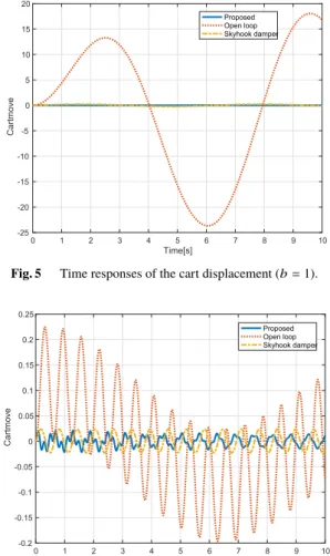
Figures 5 and 6 show the time responses of the cart displace- ment in the open loop system and closed-loop systems, when b=1 and 10, respectively. We can see that the vibration of main body is suppressed effectively in the closed-loop system with the proposed controller, while the open-loop system has only a small vibration suppression effect. On the other hand, there is no obvious difference between the performance of
Fig. 5 Time responses of the cart displacement (b=1).
Fig. 6 Time responses of the cart displacement (b=10).
skyhook damper method and the one of proposed method.
Thus, we confirmed that the proposed method can achieve the same good vibration suppression effect as the skyhook damper method without world-coordinate measure- ments.
7. Conclusion
In this paper, we have solved vibration suppression problem of the general port-Hamiltonian system via designing IDA- PBC controller. The considered system can be expressed as any floating nonlinear mechanical structure with spring and damper. We have shown the matching condition between the controlled system and the desired system. We show a control law including some free parameters with some con- straints. The controller uses only relative information, which can be easily measured. We propose a new parameter design method for more generalized nonlinear controlled objects than the previous work[12]. We show differential equations that determine the inertia matrix of the desired closed-loop system. The stability of the nonlinear closed-loop system is guaranteed theoretically by the IDA-PBC method. We have proposed an efficient parameter selection scheme achieving a good vibration suppression effect. Under the proposed pa- rameter selection, the proposed control law realized a virtual
skyhook damper using only relative informations. Simula- tion results for an example verify the good vibration effect of the proposed controller.
References
[1] D. Hrovat, “Survey of advanced suspension developments and related optimal control applications,” Automatica, vol.33, no.10, pp.1781–
1817, 1997.
[2] D. Karnrop, M.J. Crosby, and R.A. Harwood, “Vibration control us- ing semi-active force generators,” J. Eng. Ind., vol.96, no.2, pp.619–
626, 1974.
[3] J. Alanoly and S. Sanker, “Semi-active force generators for shock isolation,” J. Sound Vib., vol.126, no.1, pp.145–156, 1988.
[4] D. Sammier, O. Sename, and L. Dugard, “Skyhook andH∞control of semi-active suspensions: Some practical aspects,” International Journal of Vehicle Mechanics and Mobility, vol.39, no.4, pp.279–
308, 2003.
[5] J. Emura, S. Kakizaki, F. Yamaoka, and M. Nakamura, “Develop- ment of the semi-active suspension system based on the sky-hook damper theory,” SAE Technical Paper, SAE International, 1994.
[6] D. Hrovat, “Applications of optimal control to advanced automo- tive suspension design,” J. Dynamics, Measurement, and Control, vol.115, no.2B, pp.328–342, 1993.
[7] S. Nagarajaiah, M.A. Riley, and A. Reinhorn, “Control of sliding- isolated bridge with absolute acceleration feedback,” J. Engineering Mechanics, vol.119, no.11, pp.2317–2332, 1993.
[8] A. Ulsoy, D. Hrovat, and T. Tseng, “Stability robustness of LQ and LQG active suspensions,” ASME J. Dynamic Systems, Measurement and Control, vol.116, no.1, pp.123–131, 1994.
[9] H. Li, X. Jing, H.K. Lam, and P. Shi, “Fuzzy sampled-data control for uncertain vehicle suspension systems,” IEEE Trans. Cybern., vol.44, no.7, pp.1111–1126, 2014.
[10] A. Moran and M. Nagai, “Analysis and design of active suspensions by H∼robust control theory,” JSME International Journal. Ser. 3, Vibration, Control Engineering, Engineering for Industry, vol.35, no.3, pp.427–437, 1992.
[11] W. Sun, Z. Zhao, and H. Gao, “Saturated adaptive robust control for active suspension systems,” IEEE Trans. Ind. Electron., vol.60, no.9, pp.3889–3896, 2013.
[12] T. Aoki, Y. Yamashita, and D. Tsubakino, “Vibration suppression for mass-spring-damper systems with a tuned mass damper using interconnection and damping assignment passivity-based control,”
Int. J. Robust Nonli. Control, vol.26, no.2, pp.235–251, 2016.
[13] J. Ormondroyd and J.P. den Hartog, “The theory of the dynamic vibration absorber,” Trans. American Society of Mechanical Engi- neers, Applied Mechanics, vol.50, no.7, pp.9–22, 1928.
[14] R. Ortega, A.J. van der Schaft, B. Maschke, and G. Escobar, “Inter- connection and damping assignment passivity-based control of port- controlled Hamiltonian systems,” Automatica, vol.38, no.4, pp.585–
596, 2002.
[15] S. Hao, Y. Yamashita, and K. Kobayashi, “Vibration suppression of Hamiltonian systems with velocity and force disturbances using IDA-PBC,” 2nd IFAC Conference on Modelling, Identification and Control of Nonlinear Systems MICNON 2018, Elsevier, 2018.
[16] S. Willy and F. Cantrijn, “Generalizations of Noether’s theorem in classical mechanics,” Society for Industrial and Applied Mathemat- ics, vol.23, no.4, pp.467–494, 1981.
Sheng Hao received his B.E degree from Harbin Institute of Technology, China, in 2016, and the M.I.S. degree from Hokkaido Univer- sity, Japan, in 2019. He is currently a Ph.D.
student at the Graduate School of Information Science and Technology, Hokkaido University.
His research interests include vibration control of nonliear systems.
Yuh Yamashita received his B.E., M.E., and Ph.D. degrees from Hokkaido University, Japan, in 1984, 1986, and 1993, respectively. In 1988, he joined the faculty of Hokkaido Univer- sity. From 1996 to 2004, he was an Associate Professor at the Nara Institute of Science and Technology, Japan. Since 2004, he has been a Professor of the Graduate School of Information Science and Technology, Hokkaido University.
His research interests include nonlinear control and nonlinear dynamical systems. He is a mem- ber of the SICE, ISCIE, RSJ, and IEEE.
Koichi Kobayashi received the B.E. degree in 1998 and the M.E. degree in 2000 from Hosei University, and the D.E. degree in 2007 from To- kyo Institute of Technology. From 2000 to 2004, he worked at Nippon Steel Corporation. From 2007 to 2015, he was an Assistant Professor at Japan Advanced Institute of Science and Tech- nology. Since 2015, he has been an Associate Professor at the Graduate School of Information Science and Technology, Hokkaido University.
His research interests include discrete event and hybrid systems. He is a member of IEEE, IEEJ, IEICE, ISCIE, and SICE.