回転ピンによる鉄鋼とアルミニウム合金の固相接合*
-回転ピンによる異種材料の固相接合(第1 報)-渡辺 健彦**,柳沢 敦**,高山 博史***
Solid State Welding Aluminum Alloy to Steel Using a Rotating Pin*
-Solid State Welding of Dissimilar Metals Using a Rotating pin (Report 1)- by WATANABE Takehiko**, YANAGISAWA Atsushi** and TAKAYAMA Hirofumi*** Authors tried to butt-weld a mild steel plate to an aluminum alloy plate by the solid slate welding using a rotating pin.This study investigated the effects of a pin rotation speed, the position for the pin axis to be inserted and the pin diameter on the tensile strength and the microstructure of the joint. The main results obtained are as follows :
Butt-welding of a steel plate to an aluminum alloy plate was easily and successfully achieved. The maximum tensile strength of the joint was about 86% of that of the aluminum alloy base metal. Many fragments of the steel were scattered in the aluminum alloy matrix, and fracture tended to occur along the interface between the fragment and the aluminum matrix. A small amount of intermetallic compounds was formed at the upper part of the steel/aluminum interface, while no intermetallic compounds were observed in the middle and bottom parts of the interface. A little intermetallic compound was also often formed at the interface between the steel fragments and the aluminum matrix. The regions where the intermetallic compounds formed seem to be fracture paths in a joint.
Key Words: Joining of dissimilar metals, Steel, Aluminum alloy, Rotating pin, Tensile strength of joint, FSW
1. 緒 言 地球環境の保全や省エネルギーは早急に取り組まなけれ ばならない重要な課題であり,その対応策の一つとして車両 等の軽量化が進められている。車両としての強さを維持しつ つ,軽量化するためには鉄鋼材料とアルミニウム合金を組み 合わせた構造は有効であり,鉄鋼とアルミニウム合金を溶 接・接合するいろいろな試みがなされている。しかし,鉄と アルミニウムを溶融溶接すると,溶接部には硬くてもろい金 属間化合物が生成するために,溶融溶接による健全な継手は 作製されていない。 現在のところ,鉄鋼とアルミニウムの継手の作製には,金 属間化合物が生成しにくい接合法である爆発圧接法によっ て作製した移行継手を介して鉄鋼同士およびアルミニウム 同士を溶接する方法1),摩擦圧接法2),超音波接合法3) や圧 延接合法 4) 等のいわゆる固相接合法が主に適用されている。 しかし,移行継手を用いる方法では,移行継手の製造が容易 ではなく高コスト,工程数の増加や継手形状が制限される等 の欠点がある。また,摩擦圧接法では,少なくとも一方の部 材の断面形状が円形であることが必要であり,継手形状が制 限される。さらに,超音波接合法や圧延接合法では,薄板に しか適用できない等の欠点がある。最近では,レーザを鉄鋼 側に照射して加熱し,鉄鋼側からの熱伝導でアルミニウムの 接合面だけを溶融させて接合する方法 5) が試みられている が,入熱制御と溶融量制御が難しいことやレーザ装置が高価 等の難点がある。 そこで,異種金属を容易に接合することを目的に,「回転 ピンによる固相接合法」6) によって,鉄鋼とアルミニウム合 金の接合を試みた。 2. 本研究における回転ピンによる固相接合法について 回転ピンによる固相接合法についてFig. 1 を用いて説明す る。⒜は鳥瞰模式図で,⒝は接合線と直角に切断した模式図 である。図に示すように,回転ピンの大部分をアルミニウム 側に挿入する。つづいて,⒝のように鉄鋼側の接合面に回転 ピンを押しつけて回転側面で擦することによって酸化皮膜 を除去して新生面を露出させて活性化させる。回転子のショ ルダーとの摩擦熱で塑性流動状態となったアルミニウムを この活性面へ凝着させて接合を完了する。回転ピンの大部分 を軟らかいアルミニウム側に挿入することからピンの摩滅 もほとんど生じない。 本研究の方法で,鉄鋼とアルミニウムの突き合わせ接合線 のほぼ真上の位置に回転ピンを挿入すると,回転ピンは容易 に摩滅してしまうこと,そして,両金属はうまく混合せずに, *原稿受付 平成 15 年 2 月 27 日 平成 14 年度秋季全国大会で発 表,平成15 年 1 月界面接合研究委員会で発表 **正 員 新潟大学工学部 Member, Faculty of Engineering,
Niigata University
*** 新潟大学大学院 Student Member, Graduate School, Niigata University
接合ができないことを確かめている。この点については 4.3 項で言及する。
3. 接合材および実験方法
接合材は,板厚 2 mm の SS400 軟鋼板(以後,Fe と表記) とA5083-H24(4.5 mass% Mg,0.5 mass% Mn,残部 Al。引
張強さは275 MPa)アルミニウム合金板(以後,Al と表記) であり,入手状態のまま用いた。接合試片の形状・寸法は長 さ140 mm,幅 40 mm の矩形板である。その長手方向が圧延 方向と直角になるように母板から切り出した。Fe および Al 試片の長さ140 mm の接合面を#400 のエメリー紙で研磨後, 突き合わせてジグに固定した。接合は,フライス盤を用いて 行った。 回転子は工具鋼で作製した。ピンの長さは1.9 mm とし, 直径は 1 mm,2 mm,3 mm および 4 mm と変化させたが, 実験には,主に直径 2 mm のピンを用いた。ショルダーの直 径は15 mm である。なお,ピンにはネジは施されていない。 Fig. 1 に示すように, ピンの回転方向は時計回りで,溶接 方向に向かって左側にFe 試片を右側に Al 試片を配置した。 接合速度は25 mm/min で一定とし,ピン回転速度を 1.67,4.17, 8.33 および 20.83 s-1 の 4 段階で変化させた。また,Fe 接合 面への回転ピンの押し込み量をFig. 2 に示すように定義して 変化させた。つまり,Fe 接合面とピン側面が一致するとこ ろを基準点零とし,Fe 側への押し込み量をプラスとした。 ピンを回転させながらAl 側に挿入後,ピンを移動させて所 定の押し込み量になるように調整した。ピンは試験片に垂直 に挿入し,回転子のショルダー部は接合材表面から約 0.1 mm 侵入させた。 各接合条件下で作製された継手について,接合部の表面観 察,断面組織の観察や元素分析等を行った。また,継手の引 張強さを求めるための引張試片は,接合部が試片のほぼ中央 に位置するように接合線と直角になるように放電ワイヤカ ット機で切り出し,#400 のエメリー紙研磨によって表面お よび裏面を平坦にした後,引張試験に供した。引張試片の平 行部幅は6.25 mm で平行部長さは 37.5 mm である。 4. 実験結果および考察 4.1 ピン回転速度と接合状態と継手の引張強さ ピンの押し込み量を0.2 mm(つまり,ピン回転側面を接 合面からFe 側へ 0.2 mm 移動)とし,ピン回転速度を変化さ せて接合部の表面状態や断面の様相を調べた。その結果を Fig.3 に示す。また,Fig.4 にはピン回転速度と継手の引張強 さの関係を示す。図中に,入手のままのAl 母材の引張強さ も示した。 回転速度が1.67 s-1 の場合は,回転子が低速回転のために 発熱量が少なくAl の変形抵抗が大きくなり,ピンの摩滅が 異常に早く生じた。その結果,全接合線の約4 分の 1 しか接 合されず,残部はショルダーに擦られた表面部だけが接合し ていた。したがって,破断は未接合の接合界面に沿っており, 引張強さは低かった(破断経路は破線で示す。以後同じ)。 回転速度が4.17 s-1 になると,接合は健全に行われて破断は Al 内に散在する Fe 片(矢印で示す。EDS 分析で Fe と同定) の近傍で生じる傾向にあるが,引張強さは最大となり,Al 母材強さの約86 % となった。回転速度が 8.33 s-1 では,接
Fig. 1 Schematic illustration of solid state welding using a rolating pin : ⒜ Bird’s eye schematic view of the method and ⒝ schematic view of the cross section perpendicular to weld line.
Fig. 2 Schematic illustration to explain the relation between the pin position and the coordinate.
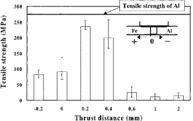
合部の表面性状は4.17 s-1 の場合と大差はないが,断面中央 部より下の部位に欠陥が発生する傾向にあった。Al 内には 大きなFe 片が存在し,破断は大きな Fe 片の近傍と欠陥を通 って生じた。引張強さは4.17 s-1 時のそれより大きく低下し た。 回転速度が20.83 s-1 になると,回転子が高速回転するた めに接合部が高温になり過ぎ,発煙が見られ,Al 合金中の Mg に起因すると考えられる燃焼が生じてほとんど接合され なかった。接合部表面にはMg に起因する燃焼が原因と思わ れる小さな穴が出現する欠陥継手となり,断面観察のための 切断作業時に接合界面から破断した。破面は焼けたように変 色していた。なお,発煙がMg に起因していることを示す直 接的な証拠は得られていない。 以上の結果から,ピン回転速度4.17 s-1 の場合に比較的良 好な結果が得られたことから,以後,ピン回転速度を4.17 s-1 として実験を進めた。 4.2 ピンの押し込み量と継手の引張強さ 接合速度を25 mm/min,ピン回転速度を 4.17 s-1 とし,Fe 側へのピン押し込み量を変化させて接合した継手の引張強 さを調べた。その結果をFig. 5 に示す。 ピン押し込み量が零あるいは負の場合(つまり,ピン側面 がFe 接合面に接する時あるいは Al 内に位置する時に相当) は,継手の引張強さはあまり大きくない。押し込み量が0.2 mm で引張強さは最大となり,これ以上では,ピン側面が Fe 側に押し込まれていくほど引張強さは低下した。 4.3 ピン押し込み量と接合部断面組織と破断経路 Fig. 6 にピン押し込み量を変化させたときの接合部断面組 織と引張試験後の破断経路を破線で示す。ピン押し込み量が 負や零の時はピン側面によるFe 接合面の酸化皮膜の除去が
Fig. 3 Effects of a pin rotation speed on the surface view, cross sectional structure and fracture path of welds.
Fig. 4 Relation between a pin rotation speed and the tensile strength of joints.
ピン押し込み量が0.6 mm や 1.0 mm になると,Al 内には Fe が塊状に存在し,さらに,大きな欠陥も発生しており, 継手の引張強さは大きく低下している。なお,ピン押し込み 量が1.0 mm の場合の継手では,図に示すように破断は複数 の箇所で生じ,また,Fe との摩擦が大きいためにピン先端 が容易に摩滅した。ピン押し込み量1.0 mm の場合,直径 2 5. 接合部の断面組織の分析と破面観察 5.1 接合線に垂直な断面組織 接合速度25 mm/min の場合,ピン回転速度 4.17 s-1 ピン 押し込み量0.2 mm で最大引張強さの継手が得られたが,こ の継手の接合線に垂直な断面組織をSEM 観察し,Fe と Al の接合界面での金属間化合物の生成の有無等を調べた。 Fig. 7 に,左側の SEM 写真中の断面上部⒜,中央部⒝と下 部⒞の拡大SEM 像と EDS による Fe と Al の線分析結果を示 す。倍率5,000 倍の SEM 観察と EDS 分析結果からではある が,断面中央部および下部のFe と Al の接合界面には金属間 化合物は観察されなかった。一方,断面上部には⒜に見られ るように層状組織が観察され,Fe と Al の線分析線にステッ プが見られることから金属間化合物が生成していることが わかる。そこで,Fig. 8 に示す⑴点と⑵点を EDS によって定 量分析した。その結果,⑴点は40.85 % Fe-48.26 % Al-5.73 % Mg-5.16 % O で⑵点は 19.61 % Fe-70.26 % Al-5.27 %
Fig. 5 Relation between the thrust distance of a pin and the tensile strength of joints.
Fig. 7 SEM images and line analyses of Fe and Al around the interface between steel and aluminum alloy : ⒜ Upper position and ⒝ middle position and ⒞ bottom position.
Fig. 9 Cross sectional view of the broken part of the joint after tension test. It is seen that fracture occurred along the interface between steel fragment and aluminum matrix.
Fig. 8 Quantitative analyses of the phases at the positions indicated by ⑴ and ⑵.
Fig. 10 Enlarged optical micrographs of parts ⒜ and ⒝ in Fig. 9. Intermetallic compounds appeared at the part ⒜ of the interface between steel fragment and alumi-num matrix. No intermetallic compounds appeared at the part ⒝.
Fig. 9 は,破断後の断面の一例を示す。前述のように,破 断がAl 内に散在した Fe 片と Al マトリックスとの界面を通 って生じていることが分かる。矢印で示す箇所にはFe 片と Al マトリックスとの界面が開口しており,この界面に亀裂 が発生しやすいことを示唆している。そこで,この写真中の ⒜と⒝の枠部を拡大して界面を観察した。拡大写真をFig. 10 の⒜と⒝に示す。⒜部には矢印で示すような相が出現してい た。この相を EDS によって定量分析すると,その組成は
21.17 % Fe-67.62 % Al-4.85 % Mg-6.36 % O(at%)で,ビッカ ース硬さは HV630 であり,FeAl3 金属間化合物と推定され
次に,前項で述べた継手について,接合線に平行な縦断面 組織のSEM 写真を Fig. 11 に示す。Fe と Al の界面から Al 側へ約700 µm 入った位置(写真中の破線位置)で Al 内に散 在する Fe 片部を通る縦断面を観察した。SEM 像から,Al 中のFe 片は接合方向に点在していることがわかる。 Fig. 12 には,この継手の破断面の SEM 写真を示す。⒜は 破断面のマクロ写真である。⒝はAl 側の拡大写真であるが, Fe 片に沿って破壊が進行したような凹凸が見られる。これ は,前述のようにFe 片と Al との界面で破断が生じやすいこ とから,Fig. 11 の縦断面の Fe 片の存在形態に良く対応して
Fig. 11 Cross sectional SEM image longitudinal to welding direction. Many steel fragments are observed in aluminum matrix.
Fig. 12 Fracture surface of the weld made under the optimal welding conditions : ⒜ Macro-photo of fracture surface, ⒝ SEM image of fracture surface and ⒞ enlarged SEM image of ⒝. Fracture seems to occur along the interface between steel fragments and aluminum matrix, and dimple pattern is observed in the fracture surface.
いる。破面をさらに拡大すると⒞に示したようにディンプル パターンが見られ延性破壊したことが分かる。 6. 回転ピンの直径を変化させた場合 これまでは,回転ピンの直径を 2 mm として接合実験を行 ってきた。次に,ピン押し込み量を0.2 mm とし,ピンの直 径を 1 mm,3 mm と 4 mm に変えて接合した継手の引張強 さをFig. 13 に示す。回転ピンの回転速度は 4.17 s-1 で接合 速度は25 mm/min である。ピン径が 1 mm の場合は,ピン は直ぐに摩滅して接合は不可能であった。ピン径が 3 mm お よび 4 mm の継手の引張強さは 2 mm の場合とほとんど変 わらないことが判明した。また,接合部の断面組織もピン径 2 mm のそれとほぼ同じであった。 7. 回転子を反時計回転にして接合した場合 次に,前節までとは異なり,回転子を反時計回転させた場 合の影響を調べた。実際は接合方向を反対にすることによっ てその影響を調べた。ピン径は 2 mm,回転子の回転数は 4.17 s-1 接合速度を 25 mm/min として接合した。 接合部の表面写真をFig. 14 の⒜に示す。表面状態だけを 見ると一見接合しているように見えるが,接合箇所は表面部 だけであり,亀裂も見られる。断面観察のために接合体を切 断する時点で破断してしまい,内部は全く接合されなかった。 ⒝は破断後のFe と Al の破面のマクロ写真であるが,ほとん ど平坦になっており,接合された形跡が見られない。 次に,接合前にFe 接合面に#400 エメリー紙で接合片の長 手方向に対して約45 度の角度に研磨痕を付け,接合前後の 接合面のSEM 観察を行った。観察結果を Fig. 15 に示す。⒜ は接合前のSEM 写真である。⒝はピン押し込み量 0.2 mm で
Fig. 13 Relation between the tensile strength of joints and pin diameter.
Fig. 14 Surface view and fracture surface of the weld when the welding direction was reversed, that is, the pin rotation direction was counterclockwise.
Fig. 15 SEM photographs showing steel faying surfaces before and after welding when the welding direction was reversed : ⒜ Before welding, ⒝ after welding with the thrust distance of 0.2mm and ⒞ after welding with the distance of 0.4 mm.
接合した後のFe 接合面の SEM 写真である。接合前の研磨痕 がピン側面で擦られた様相がみられるが,接合は全くなされ ていない。⒞はピンの押し込み量が0.4 mm の場合の Fe 接合 面である。ピンの側面でさらに擦られた様相がみられるが, 接合は全くされていない。 ピン回転が反時計回転になる(接合方向を反対にする)と, 接合しない理由を,Fig. 16 の模式図で説明する。⒜は接合方 向に向かって左側にFe を右側に Al を配置してピンを時計回 転させて接合した場合で,⒝は接合方向を逆にした場合であ る。⒜のピン回転が時計回転の場合は,塑性流動状態の Al は矢印のような回転運動をして,回転ピン側面で擦られて活 性化しているFe 接合面(太い実線で示す)に押しつけられ て凝着し,接合が達成される。一方,⒝のように接合方向を 反対にすると,矢印のように回転運動している塑性流動状態 のAl は未だ活性化されていない Fe 接合面(破線で示す)に 押しつけられることになり,接合されない。 8. 結 言 異種金属を容易に接合することを目的に,回転ピンを用い た固相接合法によって,鋼とマグネシウム含有アルミニウム 合金の接合を試みた。継手の接合強さおよび接合部の組織に ンの摩滅が顕著になる。また,回転速度が大きくなると, 温度上昇が過度になりアルミニウム合金中のマグネシウ ムが燃焼して健全な接合体は得られない。 3) 鋼側へのピンの押し込み量が約 0.2 mm で継手の接合強さ は最大になる。鋼破片がアルミニウム合金中に散在し,そ れらの界面に少量の金属間化合物が生成する場合が観察 され,その界面が破断経路になる傾向がみられる。 4) 鋼とアルミニウム合金の接合界面には,金属間化合物の生 成はほとんどみられないが,回転ショルダーとの摩擦で高 温になる界面上部に少量の金属間化合物が生成される。 5) 接合進行方向に向かってアルミニウム合金を右側に配置 して,回転子を反時計回転にすると,本研究における接合 条件範囲内では接合は不可能である。 参 考 文 献
1) For example, Japan Welding Society : 溶接・接合便覧, Maruzen, 1990, 496. (in Japanese)
2) For example, M. Aritoshi and K. Okita : Friction welding of dissimilar metals, J. of Japan welding Society, Vol. 71, No. 6, 2002, 432-436. (in Japanese)
3) For example, T. Watanabe, A. Yoneda and A. Yanagisawa : Ultrasonic welding of dissimilar metals (1st report and 2nd report), Quarterly J. of Japan Welding Society, Vol. 17, No. 5, 1999, 223-242. (in Japanese)
4) For example, T. Kohno : Production of Al/SUS Clad Material Using Vacuum Roll Bonding and its Characteristics, J. of Japan welding Society, Vol. 71, No. 6, 2002, 427-431. (in Japanese)
5) S. Katayama : Dissimilar metal welding by laser , Welding Technology, Vol. 50, No. 2, 2002, 69-73. (in Japanese)
6) T. Watanabe et al : Joining of steel to aluminum alloy by interface activated adhesion welding, Preprints of The National Meeting of J.W.S, No. 71, Autumn, 2002, 446-447. (in Japanese)
7) T.B. Masalski et al edited : Binary Phase Diagrams, ASM, 1996, CD.
8) P. Ulysse : Three-dimensional modeling of the friction stir-welding process, International Journal of Machine Tools & Manufacture, 42 (2002), 1549-1557.
Fig. 16 Schematic illustration explaining the reason why the counterclockwise rotation of a pin cannot weld aluminum to steel : ⒜ Clockwise rotation of a pin and ⒝ counterclockwise rotation of a pin.