A Wearable Augmented Reality System for Navigation Using Positioning Infrastructures and a Pedometer
2
0
0
全文
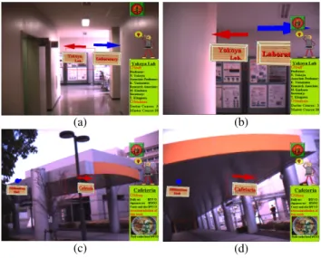
(2) Inertial Sensor Display Device INTERTRAX2 (INTERSENSE). User’s Orientation Camera. Dragonfly (PointGreyResearch). Clip On Display (Micro Optical). (a). (b). (c). (d). Annotation Overlay Image. Real Scene Image RFID Tag Reader. V720 (OMRON). IrDA Receiver Pedometer. Figure 2. Annotation overlay images. Computer. Original 3D Motion Sensor (NEC TOKIN). User’s Position. Annotation Database INSPIRON 8100 (DELL). Figure 1. Hardware configuration of the proposed system. attached to the user’s headset. Components of the proposed system are described in more detail in the following. Sensors The user equips the following five sensors. The data obtained with them is transmitted to the computer through USB, IEEE1394, or serial connection. Inertial sensor (Intersense: InterTrax2 ) An inertial sensor is attached to the user’s glasses and measures the orientation of the user’s viewpoint. Camera (Point Grey Research: Dragonfly) A camera is attached to the user’s headset and captures the real scene image from the user’s viewpoint. It can capture RGB 24bit color image of 640 × 480 pixels. IrDA receiver (Original) An IrDA receiver is attached to the user’s bag as shown in Figure 1. The IrDA receiver receives infrared ray including position IDs. RFID tag reader (OMRON: V720) An RFID tag reader is attached to the user’s wrist as shown in Figure 1. The RFID tag reader reads the position IDs recorded in RFID tags. Pedometer (NEC TOKIN: 3D motion sensor) A pedometer can measure pitch, roll, and yaw. It can also measure accelerations in the horizontal directions. Computer (DELL: Inspiron8100, PentiumIII 1.2GHz, 512Mbytes memory) A computer is carried in the user’s shoulder bag. It holds a database of annotation information for generating annotation overlay images.. Display device (MicroOptical: Clip On Display) A display device is a video see-through display device. It is attached to headset as shown in Figure 1. It can present a 640 × 480 color image to the user.. 4. Experiment and Concludion We have carried out an experiment using the proposed wearable AR system in our campus. Figure 2 (a) and (c) show the annotation overlay images when the system identifies the user’s position using positioning infrastructures, and (b) and (d) in Figure 2 are ones at the user’s position estimated with the pedometer when the user walks some steps from components of positioning infrastructures. We have proposed the annotation overlay system on a wearable computer using positioning infrastructures and a pedometer. We have also shown that the proposed system can be used both indoors and outdoors seamlessly through the experiment. Acknowledgments This research is partially supported by Core Research for Evolutional Science and Technology (CREST) Program “Advanced Media Technology for Everyday Living” of Japan Science and Technology Corporation (JST) and also by the Grant-in-Aid for Scientific Research from the Ministry of Education, Culture, Sports, Science and Technology (MEXT).. References [1] S. Mann: “Wearable Computing: A First Step Toward Personal Imaging, ” IEEE Computer, Vol. 30, No. 2, pp. 25-32, 2002. [2] R. Azuma: “A Survey of Augmented Reality, ” Presence, Vol. 6, No. 4, pp. 355-385, 1997. [3] R. Tenmoku, M. Kanbara, and N. Yokoya: “A wearable augmented reality system using an IrDA device and a passometer, ” Proc. SPIE, Vol. 5006, pp. 478-486, 2003..
(3)
図
関連したドキュメント
Correspondence should be addressed to Salah Badraoui, [email protected] Received 11 July 2009; Accepted 5 January 2010.. Academic Editor:
Moreover, to obtain the time-decay rate in L q norm of solutions in Theorem 1.1, we first find the Green’s matrix for the linear system using the Fourier transform and then obtain
Eskandani, “Stability of a mixed additive and cubic functional equation in quasi- Banach spaces,” Journal of Mathematical Analysis and Applications, vol.. Eshaghi Gordji, “Stability
The system evolves from its initial state without being further affected by diffusion until the next pulse appears; Δx i x i nτ − x i nτ, and x i nτ represents the density
Let X be a smooth projective variety defined over an algebraically closed field k of positive characteristic.. By our assumption the image of f contains
Suppose D is a linear system. On the other hand, by the definition of a system composed with a pencil, the general curve of such a system may have a singular point only at the
Nonlinear systems of the form 1.1 arise in many applications such as the discrete models of steady-state equations of reaction–diffusion equations see 1–6, the discrete analogue of
Here we continue this line of research and study a quasistatic frictionless contact problem for an electro-viscoelastic material, in the framework of the MTCM, when the foundation
