IRUCAA@TDC : Effect of Connector Design on Fracture Resistance of Zirconia All-ceramic Fixed Partial Dentures
8
0
0
全文
(2) 61. Bull Tokyo Dent Coll (2011) 52(2): 61–67. Original Article. Effect of Connector Design on Fracture Resistance of Zirconia All-ceramic Fixed Partial Dentures Kozue Onodera, Toru Sato, Syuntaro Nomoto, Otoaki Miho and Mamoru Yotsuya Department of Crown and Bridge Prosthodontics, Tokyo Dental College, 1-2-2 Masago, Mihama-ku, Chiba 261-8502, Japan. Received 6 September, 2010/Accepted for publication 11 January, 2011. Abstract The purpose of the present study was to determine the relationship between crosssectional design and fracture load using a static load bearing test in yttria-stabilized tetragonal zirconia polycrystal ceramic frameworks on a molar fixed partial denture. The test framework was designed as a 3-unit bridge with two abutment teeth at the second premolar and second molar of the mandible. The cross-sectional area of the connector was 9.0, 7.0, or 5.0 mm2. In terms of shape, the cross-section was either circular or oval, with a height/width ratio of 1:1, 3:4, or 2:3. For each of the 9 combinations of crosssectional area and shape, 5 frameworks were prepared (45 in total). Frameworks were cemented to a metallic test model with adhesive resin cement. After fracture load was measured, the percentage of fracture sites was determined and the fracture surfaces observed. In terms of cross-sectional area, there was a statistically significant difference in fracture load between 9.0, 7.0, and 5.0 mm2. No significant difference in fracture load was observed between any two shapes of connector (p⬎0.05). The fracture load of all frameworks with a cross-sectional area of 9.0 or 7.0 mm2 was over 880 N, which was recognized as parafunctional occlusal force. Fracture occurred at the distal connector in 82.2% of all frameworks on average. Fracture load decreased as cross-sectional area of the connector became smaller. The cross-sectional shape used in the present study was less influential on fracture load. It appears to be clinical possible to apply a connector with a crosssectional area of 7.0 mm2. Fracture often occurred at the distal connector between the pontic and the abutment, corresponding to the second molar. Key words:. Zirconia all-ceramic FPDs—Design— Static load bearing test. Introduction. lent qualities in terms of esthetics and biocompatibility7,12–14,19). All-ceramic fixed partial dentures (FPDs) have also begun to be used clinically. Through recent advances in CAD/. In recent years, all-ceramic crowns have seen increased clinical use due to their excel-. This paper was a thesis submitted by Dr. K. Onodera to the Graduate School of Tokyo Dental College.. 61.
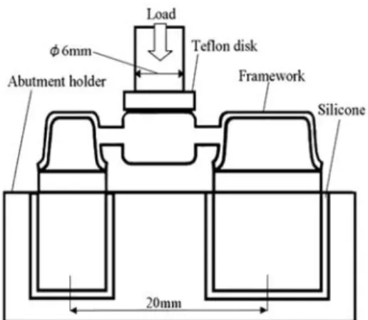
(3) 62. Onodera K et al.. CAM systems, it is now possible to use 3 vol% yttria-stabilized tetragonal zirconia polycrystals (Y-TZP) in dentistry. Yttria-stabilized tetragonal zirconia polycrystals have been attracting close attention as a material offering excellent esthetic features and remarkable strength21). Studies have been conducted on the clinical application and evaluation of molar FPDs made of Y-TZP18) and the cross-sectional area of Y-TZP FPDs4). The outstanding feature of Y-TZP ceramics is that they are hard enough to allow their use in the molar region. It is sometimes difficult to secure the proper cross-sectional area and shape in terms of the height of the connector of an FPD in the molar region due to the shape of the abutment tooth. A few studies have been published regarding connectors, including with regard to the morphology of the embrasure with use of lithium disilicate glass ceramics15,16). A few studies have also been reported regarding the connectors of zirconia prostheses containing ceramics1,17) and Y-TZP, especially with regard to the height of the connector and cross-sectional area using a finite element method. The purpose of the present study was to determine the relationship between crosssectional design and fracture load in a Y-TZP ceramic framework.. Materials and Methods 1. Materials The material tested was 3 vol% yttriastabilized tetragonal zirconia polycrystal (YTZP: Kavo Everest® Zirconium Soft, Kavo, Biberach, Germany). This type of zirconia can be used in preparing all-ceramic FPDs for the molar region. 2. Preparation of test frameworks The metallic master model was designed as a 3-unit FPD with the second premolar and second molar as the abutment teeth in the mandible. The master model was made of stainless steel. The diameter of the abutment was 7.0 mm or 11.0 mm, corresponding to the. Fig. 1 Designs of cross-section connectors. second premolar and second molar, respectively. The axial surface had a taper of 6°, and the abutment had a height of 5.0 mm. The periphery was designed as a deep chamfer with a curvature radius of 1.0 mm. The distance between abutments was 20.0 mm. A coping with 0.55 mm in thickness, 2.0 mm in connector length, and 8.0 mm in pontic width and a flat occlusal surface was designed. The cement space of the coping was set to be 45 m. The framework was designed with 3 sizes of cross-sectional area: 9.0, 7.0, or 5.0 mm2. Among these 3 sizes, the cross-sectional shape of the connector was designed to assume a circular or oval shape with the height/width ratio of 1:1, 3:4, or 2:3 (Fig. 1). At first, an impression of the metallic master model for the FPD abutment was taken to make a working cast. Scanning of the working cast with ultra-hard plaster (Kavo Everest® Rock, Kavo) specifically used for this purpose was carried out with the CAD/CAM System (Kavo Everest® System, Kavo), followed by computerized design of the framework. Milling and sintering of semi-sintered zirconia was then carried out to complete the framework. Millering and sintering of semi-sintered zirconia was then carried out to complete the framework. Five frameworks were prepared for each design (45 frameworks in total). Test modes made to the same specifications as the master model and inserted into the abutment holder. Silicone material 1.0 mm in.
(4) 63. Connector Design of All-ceramic FPDs. Fig. 2 Test device for determination of static load bearing of 3-unit framework Fig. 3 Load required for fracture by type of connector. thickness was placed between the abutment holder and the test model. After the frameworks were fabricated, each coping was checked to see that it fitted well at the margin using silicone impression material (Fit Checker, GC, Tokyo, Japan). Each framework was cemented to the test model with adhesive resin cement (ResiCem: LOT12060701, SHOFU, Kyoto, Japan) according to the manufacturer’s instructions. The cemented framework was immersed in distilled water (37°C) for 24 hr. 3. Testing method The static load bearing test was carried out at a constant cross-head speed of 1.0 mm/min with a universal testing machine (Autograph AG-I 20kN, SHIMADZU, Kyoto, Japan), and the load was applied at the pontic with a stainless steel stamp-type cylinder in the axial direction of the tooth until fracture occurred in each framework (Fig. 2). A teflon disk was used as a shock absorber material between the loading cylinder and the pontic. The 2 mm thick teflon disk was replaced with a new one at each examination. After the static load bearing test, the site of the fracture of the connector was determined. The fractured surface conditioned with Au-Pd coating material was observed through a scan-. ning electron microscope ( JSM-6340F, JEOL, Tokyo, Japan). 4. Statistical analysis Data on fracture load were subjected to a two-way analysis of variance (ANOVA) involving two factors (area and shape of connector). In addition, a multiple comparison Tukey test was carried out. Statistical analyses were performed using the computer program SPSS ver.11 (SPSS v.11, SPSS Corp., IL, USA). A p-value of p⬍0.05 was regarded as statistically significant.. Results Figure 3 shows the data on fracture load. Mean fracture load in all sizes of cross-sectional area (9.0 and 7.0 mm2) exceeded 900 N. Ever though no remarkable differences were observed between shape of connector, these results indicated a tendency toward a higher fracture load with a shape and height/width ratio of 1:1. Table 1 shows a comparison of fracture load among the different crosssectional shapes of framework. The two-way ANOVA revealed statistically significant differences in fracture load between cross-sectional areas (p⬍0.05). In terms of cross-sectional.
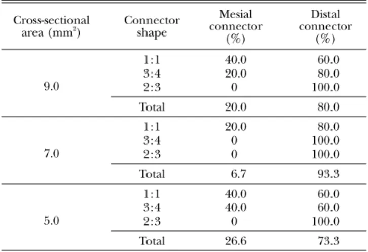
(5) 64. Onodera K et al.. Table 1 Mean fracture load of FPD frameworks Cross-sectional area (mm2). n. MeanⳲSD (N). Tukey analysis*. 9.0 7.0 5.0. 15 15 15. 1,370Ⳳ186 980Ⳳ61 755Ⳳ102. A B C. 15 15 15. 1,087Ⳳ323 1,015Ⳳ252 1,003Ⳳ290. A A A. Connector shape 1:1 3:4 2:3. * Mean with same letter were not significantly different at p⬍0.05.. Fig. 4 The observation shows the typical fractured framework under static load bearing test.. Table 2 Site of fracture Cross-sectional area (mm2). Connector shape. Mesial connector (%). Distal connector (%). 9.0. 1:1 3:4 2:3. 40.0 20.0 0. 60.0 80.0 100.0. Total. 20.0. 80.0. 1:1 3:4 2:3. 20.0 0 0. 80.0 100.0 100.0. Total. 6.7. 93.3. 1:1 3:4 2:3. 40.0 40.0 0. 60.0 60.0 100.0. Total. 26.6. 73.3. 7.0. 5.0. area, the multiple comparison revealed statistically significant differences in fracture load between 9.0, 7.0, and 5.0 mm2. No statistically significant difference in fracture load was observed between any cross-sectional shape of connector (p⬍0.05). Analysis of interaction between cross-sectional area and shape of. connector also revealed no statistically significant difference in terms of fracture load. Figure 4 shows a typical fractured framework under the static load bearing test observed at the distal connector. Table 2 shows the fracture site of the connector under the static load bearing test. When the cross-sectional.
(6) 65. Connector Design of All-ceramic FPDs. Discussion. Fig. 5 SEM observation showed cross-section of fracture. Figure represents a zoom-in from the upside to the downside.. area was 9.0, 7.0, and 5.0 mm2, fracture occurred at the distal connector in 80.0, 93.3, and 73.3% of all framework, respectively. The bottom of Fig. 5 represents a typical fractured surface on the gingival side. The fracture initiated at a point close to the gingival side of the connector. There were no differences between the mesial and distal connectors of the framework.. Several studies on the morphology of bridge connectors were primarily based on the finite element method5,11,16). Earlier reports on the load bearing testing of ceramics often investigated glass or alumina ceramics, and very few such reports on Y-TZP have been published15,16). In the present study, load bearing tests were conducted employing a 3-unit bridge designed to compensate for the loss of the lower first molar (a type of FPD frequently used clinically). In order to improve the duration of FPD restoration, it is desirable to make the crosssectional area of the framework connector as large as possible, regardless of the material used. Clinically, however, an excessively large cross-sectional area in an FPD connector is undesirable from the viewpoints of morphology and esthetics. When all-ceramic FPDs are prepared with emphasis on esthetic features, an adequate space is required at the connector to allow formation of a porcelain-based veneer. Therefore, it is important to determine the minimum acceptable cross-sectional area of the connector in ceramic frameworks. When an all-ceramic FPD framework for the molar region is designed with lithium disilicate glass or glass-infiltrated alumina ceramics, the connector is required to have a height of 5 mm and a buccolingual dimension of 4 mm if glass ceramic is used3,17), or a height of 4–5 mm and a buccolingual dimension of 3–4 mm if glass-infiltrated zirconia ceramics is used1,17). When an FPD for the molar region is prepared with Y-TZP, many manufacturers recommend that the cross-sectional area of the framework connector should be over 9.0 mm2. To achieve a cross-sectional area of 9.0 mm2 in a circular shape (a shape which can reduce stress concentration), the diameter needs to be over 3.4 mm. However, when an appropriate embrasure is reproduced with this magnitude of diameter, adequate veneer porcelain formation may be hampered. In the present study, an oval shape with longer bucco-lingual width was adopted to.
(7) 66. Onodera K et al.. secure the cross-sectional area of connector. The static load bearing tests on various Y-TZP frameworks were conducted, including ones with a connector cross-sectional area of less than 9.0 mm2 and ones with an oval shape of connector, in order to identify the crosssectional area and shape of the connector showing adequate resistance to occlusal force. Analysis of fracture load for each design generated the following findings. Fontijn et al.6) reported that maximum occlusal force was 250–400 N in the posterior dentition, and other authors suggested that parafunctional occlusal force was assumed 500–880 N2,9,10). The fracture load was higher than the maximum occlusal force for all frameworks. Also, fracture load was over 880N in all frameworks with a cross-sectional area of 9.0 or 7.0 mm2. Although it is difficult to compare the obtained results with data from clinical studies2,9,10), it is possible to that a 7.0 mm2 cross-sectional area connector is feasible. According to the result of the bending test, the fracture load was proportional to the sum of the squares of the height of connector. In the present study, the cross-sectional shape of the connector was designed to assume a circular or oval shape with a height/width ratio of 1:1, 3:4, or 2:3. There was no statistically significant difference among shapes of connector. With an oval shape connector, the radius of the gingival side increases in size. In addition, given that the fracture initiated from the gingival side of the connector, the results suggest that the radius of the gingival side of the connector reduces fracture load. Furthermore, in the present study, few differences were observed between shapes of connector, as Y-TZP is much stronger than conventional ceramics. The area in the SEM micrograph indicated by the arrow in Fig. 4 is surrounded by wrinkles radiating outward, suggesting the point of origin of the fracture. The fact that it was located close to the surface at the gingival embrasure of the connector corresponds with earlier reports4,11). Analysis of fracture site revealed that the distal connector was the site of fracture in. 82.2% of the frameworks. Thus, there was a marked tendency for fracture to occur at the connector between the pontic and abutment corresponding to the second molar. This result was the same as that reported by Sorensen et al.20) and Tsumita et al.22). Tsumita et al. attributed this tendency to the structural characteristic that the distance between the center of the distal abutment and the middle of the pontic is larger than the distance between the center of the other abutment and the middle of the pontic22). The present study was a static framework study using a universal testing machine. Bending strength determined in an earlier dynamic study was lower than the strength recorded in the present study8). Failure of FPDs with a Y-TZP framework is clinically considered as fracture of veneering ceramic material. The causes of this phenomenon are mainly derived from the strength and thickness of the veneering ceramics. Further study extending the present study, using frameworks with veneered porcelain and dynamic conditions, for example, will be necessary to verify the present findings.. Conclusions Fracture load decreased as cross-sectional area of the connector became smaller. The cross-sectional shape used in the present study was less influential on fracture load. Fracture often occurred at the distal connector, between the pontic and the abutment, corresponding to the second molar.. Acknowledgements The author would like to thank Associate Professor Jeremy Williams, Tokyo Dental College, for his assistance with the English of this manuscript..
(8) Connector Design of All-ceramic FPDs. References 1) Augereau D, Pierrisnard L, Barquins M (1998) Relevance of the finite element method to optimize fixed partial denture design. Clin Oral Invest 2:36–39. 2) Craig RG , Asgar K, Avery JK, Dennison JB, Koran A III, Myers GE, O’brien WJ, Peyton FA, Powers JM (1985) Mechanical Properties, Restorative Dental Materials, Craig RG, 7th ed., pp.60–63, Mosby, St. Louis. 3) Esquivel-Upshaw JF, Anusavice K J, Young H, Jones J, Gibbs C (2004) Clinical performance of a Lithia disilicate-based core ceramic for three-unit posterior FPDs. Int J Prosthodont 17:469–475. 4) Filser F, Lüthy H, Kocher P, Schärer P, Gauckler L J (2002) Vollkeramischer zahnersatz seitenzahnbereich Bewertung von werksoffen hinsichttlich bruchlast und zuverlässigkkeit. Quintessenz Zahntech 28:48–60. (in German) 5) Fischer H, Weber M, Marx R (2003) Lifetime prediction of all-ceramic bridges by computational methods. J Dent Res 82:238–242. 6) Fontijn-Tekamp FA, Slagter AP, Bilt AVD, Hof MAVT, Witter DJ, Kalk W, Jansen JA (2000) Biting and chewing in overdentures, full dentures, and natural dentitions. J Dent Res 31: 1519–1524. 7) Gemalmaz D, Ergin S (2002) Clinical evaluation of all-ceramic crowns. J Prosthet Dent 87: 189–196. 8) Heintze SD, Cavalleri A, Zellweger G, Büchler A, Zappini G (2008) Fracture frequency of allceramic crowns during dynamic loading and luting protocols. Dent Mater 24:1352–1361. 9) Kelly JR (1997) Ceramics in restorative and prosthetic dentistry. Annu Rev Mater Sci 27: 443–468. 10) Kelly JR (1995) Clinical failure of dental ceramic structures: Insights from combined fractography, in vitro testing and finite element. Ceram Trans 48:125–137. 11) Kelly JR, Tesk JA, Sorensen JA (1995) Failure of all-ceramic fixed partial dentures in vitro and in vivo: Analysis and methods. J Dent Res 74:1253–1258. 12) McLaren EA, White SN (2000) Survival of In-Ceram crowns in a private practice: A prospective clinical trial. J Prosthet Dent 83:216– 222. 13) Odén A, Andersson M, Krystek-Ondracek I, Magnusson D (1998) Five-year clinical evaluation of Procera AllCeram crowns. J Prosthet Dent 80:450–456.. 67. 14) Ödman P, Andersson B (2001) Procera AllCeram crowns followed for 5 to 10.5 years: A prospective clinical study. Int J Prosthodont 14:504–509. 15) Oh W, Anusavice KJ (2002) Effect of connector design on the fracture resistance of allceramic fixed partial dentures. J Prosthet Dent 87:536–542. 16) Oh W, Götzen N. Anusavice K J (2002) Influence of connector design on fracture probability of ceramic fixed-partial dentures. J Dent Res 81:623–627. 17) Raigrodski A J (2004) Contemporary materials and technologies for all-ceramic fixed partial dentures: A review of the literature. J Prosthet Dent 92: 557–562. 18) Raigrodski A J, Chiche G J, Potiket N, Hochstedler JL, Mohamed SE, Billiot S, Mercante DE (2006) The efficacy of posterior three-unit zirconium-oxide-based ceramic fixed partial dental prostheses: A prospective clinical pilot study. J Prosthet Dent 96:237– 244. 19) Segal BS (2001) Retrospective assessment of 546 all-ceramic anterior and posterior crowns in a general practice. J Prosthet Dent 85:544– 550. 20) Sorensen JA, Kang SK, Torres TJ, Knode H (1998) In-ceram fixed partial dentures: threeyear clinical trial results. J Calif Dent Assoc 26:207–214. 21) Suttor D, Bunke K, Horscheler S, Hauptmann H, Hertlein G (2001) LABA® The System for all-ceramic ZrO2 crown and bridge frameworks. Int J Comput Dent 4:195–206. 22) Tsumita M, Kokubo Y, Ohtsuka T, Nakayama Y, Fukushima S, Steyern PVV (2005) Influences of core frame design on the mechanical strength of posterior all-ceramic fixed partial dentures. part 1. Two-dimensional finite element analysis. Tsurumi Shigaku 31:203–210. (in Japanese) Reprint requests to : Dr. Kozue Onodera Department of Crown and Bridge Prosthodontics, Tokyo Dental College, 1-2-2 Masago, Mihama-ku, Chiba 261-8502, Japan Tel: +81-43-270-3938 Fax: +81-43-270-3937 E-mail: [email protected].
(9)
図


関連したドキュメント
Eskandani, “Stability of a mixed additive and cubic functional equation in quasi- Banach spaces,” Journal of Mathematical Analysis and Applications, vol.. Eshaghi Gordji, “Stability
In this, the first ever in-depth study of the econometric practice of nonaca- demic economists, I analyse the way economists in business and government currently approach
4 because evolutionary algorithms work with a population of solutions, various optimal solutions can be obtained, or many solutions can be obtained with values close to the
An easy-to-use procedure is presented for improving the ε-constraint method for computing the efficient frontier of the portfolio selection problem endowed with additional cardinality
The inclusion of the cell shedding mechanism leads to modification of the boundary conditions employed in the model of Ward and King (199910) and it will be
Let X be a smooth projective variety defined over an algebraically closed field k of positive characteristic.. By our assumption the image of f contains
Keywords: continuous time random walk, Brownian motion, collision time, skew Young tableaux, tandem queue.. AMS 2000 Subject Classification: Primary:
Related to this, we examine the modular theory for positive projections from a von Neumann algebra onto a Jordan image of another von Neumann alge- bra, and use such projections
