九州大学学術情報リポジトリ
Kyushu University Institutional Repository
真空樹脂含浸法(VARTM)によるCFRP接合継手の開発と 改良に関する研究
マハモド, ラマダン, モハメド, アブスリア
https://doi.org/10.15017/1866330
出版情報:Kyushu University, 2017, 博士(学術), 課程博士 バージョン:
権利関係:
DEVELOPMENT AND IMPROVEMENT OF CFRP ADHESIVE JOINTS USING VACUUM-ASSISTED RESIN
TRANSFER MOLDING (VARTM) By
Mahmoud Ramadan Abusrea マハムド ラマダン アブスリア
A Thesis Submitted to the
Graduate School of Engineering Sciences at Kyushu University in Partial Fulfillment of the
Requirements for the Degree of DOCTOR OF ENGINEERING
in
Molecular and Material Science
KYUSHU UNIVERSITY Fukuoka, Japan
2017
DEVELOPMENT AND IMPROVEMENT OF CFRP ADHESIVE JOINTS USING VACUUM-ASSISTED RESIN
TRANSFER MOLDING (VARTM)
By
Mahmoud Ramadan Abusrea マハムド ラマダン アブスリア
A Thesis Submitted to the
Graduate School of Engineering Sciences at Kyushu University in Partial Fulfillment of the
Requirements for the Degree of DOCTOR OF ENGINEERING
in
Molecular and Material Science Under the Supervision of
Prof. Kazuo Arakawa
Research Institute For Applied Mechanics Kyushu University
KYUSHU UNIVERSITY Fukuoka, Japan
2017
DEVELOPMENT AND IMPROVEMENT OF CFRP ADHESIVE JOINTS USING VACUUM-ASSISTED RESIN
TRANSFER MOLDING (VARTM)
By
Mahmoud Ramadan Abusrea マハムド ラマダン アブスリア
A Thesis Submitted to the
Graduate School of Engineering Sciences at Kyushu University in Partial Fulfillment of the
Requirements for the Degree of DOCTOR OF ENGINEERING
in
Molecular and Material Science
Approved by the Examining Committee
____________________________
Prof.
____________________________
Prof.
____________________________
Prof.
KYUSHU UNIVERSITY Fukuoka, Japan
2017
Name: Mahmoud Ramadan Mohamed Abusrea
Date of Birth: 1984/02/07.
Nationality: Egypt
E-mail: [email protected]
Phone: +81-080-2793-4922
Address: 4-7-8453 Hatta, Higashi-ku, Fukuoka
Registration Date: 2014/10/01
Awarding Date: …./…./……..
Degree: Doctor of Engineering
Department: Molecular and Material Science
Supervisor:
Prof. Kazuo ARAKAWA
Examiners:
Prof. Kazuo ARAKAWA Prof. Hideharu NAKASHIMA Prof. Wenxue WANG
Title of Thesis:
Development and Improvement of CFRP adhesive joints Using Vacuum-Assisted Resin Transfer Molding (VARTM)
Key Words:
CFRP joints, vacuum-assisted resin transfer molding, strength of joints
Insert photo here
i
Acknowledgments
ِميِحهرلا ِنَمْحهرلا ِ هاللَّ ِمْسب
In the name of Allah, the Most Gracious and the Most Merciful
Alhamdulillah, all praises to my god, Allah, for the strengths and his blessing in completing this thesis.
First and foremost, I wish to express my sincere gratitude and appreciation to my supervisor, Professor Kazuo Arakawa. Professor Arakawa has fully supported me not only by providing academic guidance, but in all ways. Because he has always given me unlimited freedom and motivation, I was able to indulge my passion for studying various researches without any concern or stress.
I would like to thank our laboratory secretary Ms. Yoshii. She introduced a great help to facilitate all matters belong to our lab and my life as well. I would like to thank all our lab members. I would like to extend my appreciation to prof. Todo for his kindness and generosity.
I would like to acknowledge the scholarship program from Monbukagakusho (the Ministry of Education, Culture, Sports, Science and Technology, Japan), which allowed me to concentrate on my research without financial burden.
I would like to thank prof. Choi and his student Mr. Han for hosting me in their lab in Hanyang University to do a part of the experimental work. I would like to thank Mr.
Yoon for his advises. I would like to extend my grateful to prof. Wenxue Wang and Mr.
Matsubara for giving permission to cut the samples and do a part of the experimental tests
I would like to Assoc. prof. Kalaitzidou Kyriaki and his lab members, Dr. Amir Asadi and Mr. Mohamed Shafik for hosting me in their lab in Georgia Institute of Technology.
They also introduced a great help to me during my stay in Emory hospital in Atlanta.
I would like to express my deepest gratitude to my advisory committee, Prof.
Nakashima and Prof. Wenxue Wang for screening this thesis and for their valuable advices.
I’m would like to thank all my Egyptian friends here in Fukuoka. They have supported me and guided me in many situations. I felt I have a big family here in Fukuoka.
Lastly, this thesis would not be possible without the sincere encouragement, support, and patience from my wife Ms. Zeinab Okasha. I am deeply indebted to all my family in Egypt, my mother, my sisters and my brother
Mahmoud Abusrea
マハモド アブスリア2017/06/13
ii
Dedication
To the soul of my late brother Mohamed Abusrea (1972-2012)
and my late father Ramadan Abusrea (1949-2000)
iii
Table of Contents
ACKNOWLEDGMENTS ... I DEDICATION ... II TABLE OF CONTENTS ... III LIST OF TABLES ... V LIST OF FIGURES ... VI ABSTRACT ... IX
CHAPTER 1 : GENERAL INTRODUCTION ... 1
1.1. I
NTRODUCTION... 1
1.1.1. Wind-lens turbines ... 1
1.1.2. Carbon fiber reinforced plastic (CFRP) composite materials ... 3
1.1.3. Vacuum assisted resin transfer molding VARTM process ... 4
1.1.4. CFRP composite joints ... 8
1.2. M
OTIVATIONS AND OBJECTIVES OF THE PRESENT WORK... 9
1.3. S
COPE ANDO
RGANIZATION OF THE THESIS... 10
CHAPTER 2... 13
NOVEL CFRP ADHESIVE JOINTS FOR WIND-LENS OFFSHORE STRUCTURES ... 13
2.1. I
NTRODUCTION... 13
2.2. E
XPERIMENTAL WORK... 14
2.2.1. Materials ... 14
2.2.2. Adhesive joints ... 14
2.2.3. Manufacturing ... 15
2.2.4. Test procedures ... 16
2.3. R
ESULTS AND DISCUSSIONS... 19
2.4. C
ONCLUSIONS... 24
CHAPTER 3... 26
EFFECT OF STITCHING ON THE TENSILE STRENGTH OF THE CURRENT NOVEL JOINTS CFRP ADHESIVE JOINTS ... 26
3.1. I
NTRODUCTION... 26
3.2. E
XPERIMENTALM
ETHODS... 27
3.2.1. Materials ... 27
3.2.2. Adhesive joints ... 27
3.2.3. Manufacturing ... 28
3.2.4. Test procedures ... 29
3.3. R
ESULTS ANDD
ISCUSSIONS... 31
3.4. C
ONCLUSIONS... 36
iv
CHAPTER 4... 37
IMPROVEMENT OF AN ADHESIVE JOINT CONSTRUCTED FROM CARBON FIBER-REINFORCED PLASTIC AND DRY CARBON FIBER LAMINATES ... 37
4.1. I
NTRODUCTION... 37
4.2. E
XPERIMENTAL WORK... 38
4.2.1. Staircase adhesive joints ... 38
4.2.2. Materials and testing ... 39
4.3. R
ESULTS AND DISCUSSIONS... 40
4.4. C
ONCLUSIONS... 48
CHAPTER 5... 49
TENSILE STRENGTH ENHANCEMENT OF ADJUSTED NOVEL CFRP COMPOSITE LAMINATED JOINTS FABRICATED BY VACUUM-ASSISTED RESIN TRANSFER MOLDING VARTM ... 49
5.1. I
NTRODUCTION... 49
5.2. M
ATERIALS ANDF
ABRICATIONS... 50
5.2.1. Materials ... 50
5.2.2. Adhesive joints ... 51
5.2.3. Test procedures and specimens ... 53
5.3. R
ESULTS ANDD
ISCUSSIONS... 55
5.3.1. Ultimate Tensile failure load... 55
5.3.2. Load-Displacement curves ... 57
5.3.3. Joining efficiency ... 60
5.3.4. Maximum tensile stress ... 61
5.3.5. Fracture mode ... 63
5.3.6. Thickness profile ... 67
5.4. C
ONCLUSIONS... 68
CHAPTER 6... 71
BENDING STRENGTH OF NOVEL CFRP COMPOSITE ADHESIVE JOINTS FABRICATED FROM TWO DRY CARBON HALVES USING VACUUM ASSISTED RESIN TRANSFER MOLDING ... 71
6.1. I
NTRODUCTION... 71
6.2. M
ATERIALS ANDF
ABRICATIONS... 71
6.2.1. Materials ... 71
6.2.2. Adhesive joints ... 72
6.2.3. Testing procedure ... 75
6.3. R
ESULTS AND DISCUSSION... 76
6.4. C
ONCLUSIONS... 90
REFERENCES ... 92
APPENDIX ... 102
v
List of Tables
Table 1. 1: Features of various LCM processes [14] ... 5
Table 2.1: Characteristics of the carbon fiber used for this work ... 14
Table 3.1: Characteristics of the carbon fiber used in this work ... 27
Table.4. 1: CFRP composite material constituents ... 39
Table 5.1: Characteristics of the carbon fiber used in this work ... 51
Table 5.2: Specimens’ details for tensile test ... 54
Table 6. 2: Thickness measurements for the NCLJ ... 78
Table 6. 3: Thickness measurements for the SCLJ ... 78
vi
List of Figures
Figure 1.1: Wind power turbine system with a diffuser designed by Kyushu University
[3] ... 2
Figure 1. 2: Photograph of the wind-lens power system [3] ... 3
Figure 1.3: Typical illustration of an autoclave process [12] ... 4
Figure 1.4: Typical illustration of RTM process [12] ... 6
Figure 1.5: (a) A schematic view of the VARTM process used in this work and (b) Picture of adopted VARTM process ... 6
Figure 1.6: Organization of the current research work ... 12
Figure 2.1: Joint group 1: (a) staircase joint-1, and (b) staircase joint-2... 17
Figure 2.2: Joint group 2: (a) laminated joint-1, (b) laminated joint-2, and (d) multi- overlapped joint. ... 18
Figure 2.3: The standard specimen dimensions used for tensile testing ... 18
Figure 2.4: Tensile test setup for the current work ... 19
Figure 2.5: Maximum tensile load data of joint type-1 and jointless CFRP samples .... 20
Figure 2.6: Maximum tensile load data of joint type-2 and jointless CFRP samples .... 21
Figure 2.7: A diagram of typical tensile load-displacement, with images for staircase joint-1. ... 23
Figure 2.8: Schematic drawing of a staircase joint after bonding ... 23
Figure 2. 9: Typical tensile load-displacement diagram with images for a multiple- covers joint ... 24
Figure 2.10: Schematic drawing of a multiple-covers joint with possible crack zones highlighted ... 24
Figure 3. 1: (a) Schematic top view of the staircase joints: (b) original staircase ... 29
and (c) stitched staircase joints ... 29
Figure.3. 2: (a) Schematic top view of all multiple-covers joints (b) original multiple- covers, and (c) stitched multiple-covers joints ... 30
Figure.3. 3: Schematic diagram of the VARTM process used in this work ... 30
Figure 3. 4: Standard specimen dimensions used for tensile testing and (b) an image of a specimen used in a tensile test ... 31
Figure 3. 5: Tensile loads of the two multiple-covers joints ... 33
Figure 3.6: Tensile loads of the staircase joints ... 34
Figure 3.7: Typical tensile load–displacement curve, with images of the staircase joint at different stages of the test ... 34
Figure 3.8: (a) Schematic diagram of the resin flow for stitched staircase joint, and (b) images of voids formed at the bottom of the joint ... 35
Figure 3.9: Typical tensile load–displacement curve, with images of the stitched staircase joint at different stages of the test ... 35
Figure 4. 1: (a) Schematic view of the manufacturing of the carbon fiber-reinforced plastic (CFRP) part. (b) Photograph of the fabrication of the CFRP part. (c) Schematic drawing of the resulting CFRP fabric part. ... 40
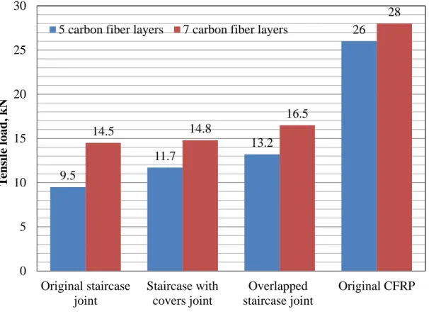
Figure 4.2: (a) Schematic view of the joints. (b) Sectional side view of the original staircase joint. (c) Sectional side view of the staircase joint with covers. (d) Sectional side view of the overlapped staircase joint. ... 41
Figure 4. 3: Standard specimen dimensions used for tensile testing. ... 41
Figure 4.4: Tensile loads of all joints compared with the original CFRP. ... 44
vii
Figure 4. 5: (a) Stress-strain curves for all joints with 7 layers and (b) A typical fracture
scenario for the staircase with covers joint at the given positions. ... 45
Figure 4. 6: Stress-strain curves for all joints with 7 layers. ... 46
Figure 4. 7: Typical optical microscopy analysis for the 7-carbon-fiber joints ... 47
Figure 5.1: (a) Jointless CFRP, (b) Laminated joint, (c) Laminated joint with 20 mm overlap, (d) Laminated joint with 40 mm overlap and (e) Multiple-covers laminated joint ... 52
Figure 5.2: (a) Standard specimen size used in this work and (b) Image for all joints .. 54
Figure 5.3: Ultimate failure load data for joinltess CFRP and joints ... 57
Figure 5.4: A typical load-displacement curve for the laminated joint OLJ ... 58
Figure 5.5: A typical load-displacement curve for the overlapped laminated joint O2058 Figure 5.6: A typical load-displacement curve for the overlapped laminated joint O4059 Figure 5.7: A typical load-displacement curve for the multiple-covers laminated joint MLJ... 60
Figure 5.8: Joining efficiency data for all joints ... 61
Figure 5.9: Maximum tensile stress based on the adherend thickness ... 62
Figure 5.10: Maximum tensile stress based on the joint thickness ... 63
Figure 5.11: Typical microscopic photographs of the jointless CFRP sample ... 65
Figure 5.12: Typical microscopic photographs of the laminated joint OLJ ... 65
Figure 5.13: Typical microscopic photographs of the overlapped laminated joint O20 66 Figure 5.14: Typical microscopic photographs of the overlapped laminated joint O40 66 Figure 5.16: Typical microscopic photographs of the multiple-covers laminated joint MLJ... 67
Figure 5.16: Typical thickness profiles for the three joints and the jointless CFRP fabric. ... 68
Figure 6. 1: (a) Schematic view of the joints. (b) Sectional side view of the laminated joint (LJ). (c) Sectional side view of the stitched laminated joint (SLJ). (d) Sectional side view of the multiple-cover laminated joint (MCLJ). ... 73
Figure 6. 2: Schematic drawing before and after molding for the (a) normal-case laminated joint (NCLJ) and (b) shifted-case laminated joint (SCLJ)... 74
Figure 6. 3: Specimen preparation. (a) Location of specimens taken from the CFRP plate and (b) an illustration of the specimen for the three-point bending testing with acoustic emission (AE) monitoring ... 77
Figure 6. 4: Bending load data for the NCLJ and SCLJ ... 78
Figure 6. 5: Bending stress-time diagram with accompanying AE amplitude for NCLJ: (a) 6 carbon fiber layers and (b) 10 carbon fiber layers ... 80
Figure 6. 6: Bending stress-time diagram with accompanying AE amplitude for SCLJ: (a) 5 carbon fiber layers and (b) 7 carbon fiber layers ... 81
Figure 6. 7: Typical percentage AE energy data for the three frequency bands for NCLJ ... 82
Figure 6. 8: Typical optical microscopy and SEM micrographs for the fracture of NCLJ with 10 layers ... 83
Figure 6. 9: Typical percentage AE energy data for the three frequency bands for SCLJ ... 84
Figure 6. 10: Typical optical micrographs for the fracture of the 5-layer SCLJ ... 84
Figure 6. 11: Bending load data for the SLJ with different layer numbers ... 86
Figure 6. 12: Typical percentage AE energy data for the three frequency bands for SLJ ... 86
Figure 6. 13: Typical SEM micrograph for the fracture of the 6-layer SCLJ ... 87
viii
Figure 6. 14: Typical thickness profiles for the three joints and the jointless CFRP
fabric ... 88
Figure 6. 15: Bending load data for the MCLJ with different layer numbers ... 89
Figure 6. 16: Typical percentage AE energy data for the three frequency bands for
MCLJ ... 89
Figure 6. 17: Typical SEM micrograph for the fracture of the 10-layer MCLJ ... 90
ix
Abstract
The use of carbon fiber reinforced plastic CFRP composites in engineering structures brings many advantages because of their high performance and mechanical properties, such as high strength-to-weight and stiffness-to-weight ratios. For this reason, they have been used for heavy duty structures in aviation, space, automotive, shipbuilding, and wind turbine applications. These applications generally involve large scale manufacturing, so the parts are produced from smaller components and are joined together. So, the mechanical performance of these structures is highly dependent on the joining efficiency. Typically, wind-lens turbine structures are fabricated in segments, and then bonded to form the final structure. The main objective of this work is to develop CFRP adhesive joints with high mechanical performance for the wind-lens and other similar structures. This is to be done by either improving the current joints and/or developing new adhesive joints. First, the emphasis is given to develop new joints. Then subsequent improvements on these joints are to be done. All CFRP joints and fabrics is made using vacuum assisted resin transfer molding VARTM manufacturing process. The thesis’s chapters are organized as follows:
Chapter 1 introduces a background and general introduction on wind-lens structures, CFRP composites, VARTM, and CFRP adhesive joints
Chapter 2 introduces five new adhesive joints, divided into two types: the first type
is constructed between dry carbon and CFRP fabrics, and the second is constructed
with two dry carbon fibers. These CFRP joints are made in our laboratory using
VARTM manufacturing technique. Specimens are prepared for tensile testing to
measure joint performance. The tensile test results show low strength when one half of
the joint is CFRP fabrics, which was the case for the first two developed joints,
x
staircase join-1 and staircase joint-2. On the other hand, second joint type such as laminated joint and multiple-covers joint, showed higher tensile strength. Fracture analysis showed the same fracture pattern, crack initiation at the joint ends followed by crack propagation until fracture.
Chapter 3 describes the effect of using the stitching technique on the tensile strength of both CFRP adhesive joint types. Tensile test results revealed improved strength when stitching was applied to the multiple-covers and staircase joints. The improvement achieved for multi-overlapped joint higher than that for the staircase joint.
For the staircase joint, the strength improvement caused by the extra carbon fiber pieces which were put at the joint ends not by applying the stitching technique.
Chapter 4 introduces the improvements that made for the first joint type. For this joint type, three adhesive joints were introduced: the first is the original stepped joint and the other two are improved stepped joints. Specimens were prepared for tensile testing to measure joint performance. The results showed an enhanced tensile load for the modified staircase joints. The percentage increase depended on the number of carbon fiber layers. For example, the total percentage increase in the tensile load recorded was 39% for the five-carbon-fiber- layer CFRP, with a further 14% increase for the seven carbon fiber layers. The final joining efficiencies reached 51% and 59%
for five- and seven-carbon-fiber-layer CFRP fabrics.
Chapter 5 introduces the improvements that made for the second joint type. Further
improvements were made by overlapping the two halves or adding extra carbon fiber
pieces. Four laminated joints were investigated: the original laminated joint (OLJ), two
overlapped joints, O20 and O40, with overlap lengths of 20 mm and 40 mm,
respectively, and a multiple-covers joint (MLJ). Specimens were prepared for tensile
xi
tests to evaluate joint performance. The overlapped joint O40 achieved the highest ultimate failure load, of 22.3 kN, with a 56% increase over the OLJ. The load- displacement curve showed a linear relationship in the first two stages for the OLJ and a non-linear relationship in the third stage. However, the entire load-displacement curve showed a linear relationship for the other joints. The joining efficiency ranged from 44.5% to 69.5% for all joints. The highest ultimate stress, of 1,250 MPa, was recorded for the O40 overlapped joint. Fracture analysis showed a delamination failure mode for the OLJ and O20 joints, while a mixture of delamination and fiber breakage failure modes was observed for the O40 and MLJ joints.
Chapter 6 continues the improvements that made for the second joint type. For this
joint type, some improvements are provided to enhance performance in terms of
bending strength. These improvements included stitching of the two halves together by
carbon fiber bundles and inserting extra carbon fiber covers in the joint connection. We
studied three adhesive joints: a conventional laminated joint and two improved
laminated joints. All joints and CFRP fabrics were made in our laboratory using
VARTM techniques. Specimens were prepared for bending tests to evaluate the joint
performance. Two acoustic emission (AE) sensors were placed on a specimen to
monitor fracture progresses during the test. The results, for the six-layer laminates,
showed a considerable improvement in bending strength for the modified laminated
joints. The percentage increases in the bending strength were 27% and 112% for
stitched and multiple-cover laminated joints, respectively.
1
Chapter 1 : General Introduction
1.1. Introduction
1.1.1. Wind-lens turbines
Due to the limited supply of fossil fuels and environmental problems caused by their use, the development of renewable and clean new energy have become global issues. Particularly in Japan, the application of alternative energy sources is very important. Nuclear energy is one alternative energy source, and it has been developed extensively in Japan. Japan generates 30% of its electrical power from nuclear reactors, and had planned to increase that to 40%. However, the Fukushima Daiichi nuclear disaster caused by the earthquake in March 2011 demonstrated the potentially fatal risks when using nuclear power. Other clean energy sources are expected to replace it.
Wind energy is a promising alternative. It is developing rapidly and will play a major role in the new energy field. However, in comparison with the overall demand for energy, the scale of wind power usage is still small; in fact, the level of development in Japan is extremely small. As an island nation, it is difficult to find suitable areas for wind-power plants. At the same time, the complex terrain and the turbulent nature of the local winds make it difficult to apply current wind-power techniques widely in Japan.
To address these problems, a new efficient wind-power turbine system has been
developed by a research group at the Division of Renewable Energy Dynamics of the
Research Institute for Applied Mechanics, Kyushu University [1-3]. This system has a
2
diffuser shroud at the circumference of its rotor to concentrate the wind energy, as shown in Figure 1.1 and Figure 1.2. This diffuser is called a “wind-lens”. With this system, even low-speed winds can be used for power. Moreover, a plan for an offshore wind farm is under study. In the future, this wind-power turbine system will likely be used offshore to harness wind power over the sea. Such a wind-power turbine system will be based on a floating structure. Consequently, high-strength and lightweight materials will be required.
Generally, there are three requirements for materials in a turbine system [4]:
1. High material stiffness is needed to maintain optimal aerodynamic performance, 2. Low density is needed to reduce gravity forces, and
3. Long fatigue life is needed to reduce material degradation.
Figure 1.1: Wind power turbine system with a diffuser designed by Kyushu
University [3]
3
Figure 1. 2: Photograph of the wind-lens power system [3]
1.1.2. Carbon fiber reinforced plastic (CFRP) composite materials
Fiber-reinforced composite materials are promising candidates for many
applications such as aviation, space, automotive, shipbuilding as well as wind turbines
[5-11]. They have excellent mechanical properties in terms of stiffness-to-weight and
strength-to-weight ratios. By far, the most widely used fibers are glass fibers, carbon
fibers, aramid, polyethylene, and cellulose [4]. Among these fibers, carbon fibers and
their composites have excellent combinations of very high stiffness, high strength, and
low density [12]. Therefore, carbon-fiber reinforced composites (CFRPs) would be
useful for fabricating a wind-lens for a wind-power generating system at sea.
4
1.1.3. Vacuum assisted resin transfer molding VARTM process
Composite structures may be fabricated using an autoclave with a pre-preg process (See Figure 1.3). However, it is difficult to fabricate products with complex shapes and large areas using autoclaves, resulting in substantial installation costs [13].
To overcome this limitation, liquid composite molding (LCM) has been utilized as alternative method. The LCM process is one composite manufacturing method in which a low-viscous thermosetting resin is injected into a woven or stitched reinforcement placed inside a mold. Components with complex shapes can be fabricated in a single step. Two common LCM processes are resin transfer molding (RTM, Figure 1.4) and vacuum assisted resin transfer molding (VARTM, Figure 1.5), but there are also other processes such as RTM ‘light’ and compression resin transfer molding (CRTM) [14]. The features of each method are listed in Table 1.1.
Figure 1.3: Typical illustration of an autoclave process [12]
5
Table 1. 1: Features of various LCM processes [14]
LCM process Feature
RTM
Mold
configuration Two rigid molds are used to compact the product.
Advantage The finished product has very good surface quality and excellent dimensional tolerance.
Limitation
Since the process needs to push the viscous resin through the gap between two compacted molds, the injection process may require a significant amount of time, depending on the flow resistance.
VARTM
Mold configuration
A vacuum bag covers a rigid mold, and a vacuum is drawn. The vacuum plays a role in compacting the mold and drawing the resin in.
Advantage Large parts can be fabricated and the equipment cost is reduced.
Limitation The bag-side surface quality is relatively low and the dimensional tolerances are also compromised.
RTM-light
Mold configuration
Very similar to VARTM, but a compliant mold is used in the vacuum bag to improve the
dimensional tolerances. The distribution medium is usually forms an integral part.
Advantages Better surface quality compared to VARTM.
Limitations The surface uniformity is worse than VARTM and remains an issue.
CRTM
Mold configuration
The resin is injected into a partially open mold.
The resin is quickly distributed in the gap between the mold and the preform, forming a surface with high permeability. Then, the mold is closed and compacted, and the resin is squeezed into the unsaturated regions.
Advantage Production rates can be increased.
Limitation The mold requires more equipment than other LCM processes.
6
Figure 1.4: Typical illustration of RTM process [12]
Vent Inlet
Peel ply Sealant tape
(b) (a)
Figure 1.5: (a) A schematic view of the VARTM process used in this work and (b)
Picture of adopted VARTM process
7
Since this study was aimed at wind-lens turbine components, the costs and accessibility were assigned higher priorities than the products rate. Therefore, the VARTM process was selected for the LCM. Figure 1.5a shows a detailed drawing of the VARTM process.
In a VARTM process, reinforcements are stacked on a solid mold which is prepared with release agent, and covered by a peel ply and a distribution medium.
They are enclosed together with an inlet and a vent in a vacuum bag and sealed with tape. Figure 1.5b shows a photograph of a vacuum package in our experiments. After drawing vacuum in the package, the resin can be infused from the inlet by the pressure difference between the inside and the outside of the package. After the reinforcement is completely infused, the inlet is closed. In order to get a higher fiber volume fraction, the vent is usually left open to extrude the extra resin inside the vacuum package until the resin becomes too viscous to flow. After the resin cures, a laminate composite is obtained after demolding process. A release agent painted on a solid mold and peel ply are used to separate the final product from the other layers.
Without them, the final composite product will attach to the mold and the distribution medium, making the demolding process very difficult. Because the infusion pressure is only 1 atmosphere, the infusion speed inside the reinforcement is very slow. For large and thick parts, the vacuum level may not be sufficient to complete the infusion.
Consequently, a distribution medium is often required, such as a plastic mesh, which
has much higher in-plane permeability than a fabric stack, allowing for fast surface
resin wet-out. Subsequent resin penetration allows for complete infusion. A spiral
tube is often used in the inlet and vent structures to make a point inlet (and vent)
become a line inlet (and vent). It is critical to choose the location of the vent
8
appropriately to completely infuse the reinforcement and avoid creating resin-starved regions near the vent locations after the inlet is closed.
1.1.4. CFRP composite joints
The use of CFRP composite materials in engineering structures brings many advantages because of their high performance and mechanical properties, such as high strength-to-weight and stiffness-to-weight ratios [5]. For this reason, they have been used for heavy duty structures in aviation, space [7-10, 18], automotive [9], shipbuilding [7], and wind turbine applications [19]. These applications generally involve large scale manufacturing, so the parts are produced from smaller components and are joined together. The mechanical performance of these structures is highly dependent on the joining efficiency.
Because composite joints work as structure-critical load-carrying elements, the design and analysis of composite joints have attracted much attention in a series of light, low-cost, and efficient composite integration projects [20]. ‘Traditional’
mechanical fasteners, such as bolts, pins, and rivets, have been used to join CFRP
structures [21-23]. This composite joining technique is generally characterized by
simplicity and the fact that such joints can be disassembled [24]. However, drilling
holes in composite parts before fastening may cause problems due to stress
concentration and weight increases. In contrast, adhesively bonded joints have
mechanical advantages over bolted joints because the fibers are not cut, and stresses
are transmitted more homogeneously [25]. They offer better structural integrity, lower
weight, and higher strength-to-weight ratios [26, 27]. For this reason, the adhesively
bonded joints will be focused in the current work.
9
In the current work, the adhesive joints can be classified into two types: (1) dry carbon fabrics joints and (2) CFRP fabrics joints. In the first joint type, the joint’s halves are dry carbon fibers. These two halves are stacked together in different way depending on the joint design and then molded together in one time to the final joint fabric. This kind of joints is featured with high strength and short time fabrication.
The second joint constructed using at least one half of CFRP fabric. This type of joint accomplished through two molding times. The first molding is used to fabricate the CFRP fabric and the second to make the joint itself. Compared to the first joint type these joints usually achieve lower joining efficiency. However, it is easier to make CFRP parts first and then join them together rather than making the whole structure in one time which is happening in the first joint type.
1.2. Motivations and objectives of the present work
Today, adhesive composite joints are used widely in many composite structures in aerospace, turbine, and ship designs [6]. These structures are manufactured from several parts, which are joined to form the final structure. Typically, wind-lens turbine structures are fabricated in segments, and then bonded to form the final structure.
These structure usually joined conventionally using traditional joints, which include
single-lap [25, 28], double-lap [29, 30], and stepped [31, 32] joints. However, the
mechanical performance for these joints still limited. It is known that these
engineering structures are subjected to combinations of mechanical loadings,
including static, fatigue, and impact loadings. Therefore, the need for high
performance adhesive joints is very crucial.
11
The main objective of this work is to develop CFRP adhesive joints with high mechanical performance for the wind-lens and other similar structures. This is to be done by either improving the current joints and/or developing new adhesive joints.
First, the emphasis will be given to develop new joints. Then subsequent improvements on these joints will be done. All CFRP joints and fabrics will be made using VARTM manufacturing process.
1.3. Scope and Organization of the thesis
According to Figure 1.6, the remainder of this thesis is organized as follows:
Chapter 2 introduces five new adhesive joints, divided into two types: the first type is
constructed between dry carbon and CFRP fabrics, and the second is constructed with
two dry carbon fibers. These CFRP joints were made in our laboratory using VARTM
manufacturing techniques. Specimens were prepared for tensile testing to measure
joint performance. The next chapters introduce subsequent improvements for both
types. Chapter 3 describes the effect of using the stitching technique on the tensile
strength of both CFRP adhesive joint types. Chapter 4 introduces the improvements
that made for the first joint type. For this joint type, three adhesive joints were
introduced: the first is the original stepped joint and the other two are improved
stepped joints. Specimens were prepared for tensile testing to measure joint
performance. Chapter 5 introduces the adjustments were made for type 2 joints. In this
chapter the mechanical performance in terms tensile strength was measured to asses
these adjustments. The adjustments were made by overlapping the two halves or
adding extra carbon fiber pieces.
11
Four laminated joints were investigated: the original laminated joint (OLJ), two
overlapped joints, O20 and O40, with overlap lengths of 20 mm and 40 mm,
respectively, and a multiple-covers joint (MLJ). Specimens were prepared for tensile
tests to evaluate joint performance. The fracture modes for all joints were done by
optical microscopy. Finally, chapter 6 continues the improvements that made for the
second joint type. These improvements include the stitching of the two halves
together using carbon fiber bundles and inserting extra carbon fiber covers in the joint
connection. For this joint type, three adhesive joints were studied: a conventional
laminated joint and two improved laminated joints. Specimens were prepared for
bending tests to evaluate joint performance. Two acoustic emission (AE) sensors were
placed on the specimen to monitor fracture progress during the test. The fracture
modes for all joints were done by optical microscopy and/or scanning electron
microscopy SEM.
12
Figure 1.6: Organization of the current research work
13
Chapter 2
Novel CFRP Adhesive Joints for Wind-lens offshore structures
2.1. Introduction
Carbon fiber reinforced polymer (CFRP) composites are important for structural applications in the transportation industry and other areas, where lightweight design is advantageous for operational costs. When composite materials are used to fabricate a large complicated structure, joints between different parts are inevitable. As such, the structural integrity depends critically on the joint performance and not just on the basic composite structure.
This chapter introduces five new adhesive joints. These joints can be divided into two types: type 1 and type 2 joints. The first type is constructed between dry carbon and CFRP halves, and the second is constructed between two dry carbon fibers halves.
These CFRP joints were made in our laboratory using VARTM manufacturing
techniques. Specimens were prepared for tensile testing to measure joint performance
novel adhesive bonded joints, made of CFRP, for using in offshore wind-lens
structures. These newly developed joints are dedicated to the offshore wind-lens and
other similar structures. The tensile strength of five joints will be assessed. All joints
and CFRP material tested in this study were made using a VARTM process.
14
2.2. Experimental work
2.2.1. Materials
The CFRP composites consisted of carbon fabric and a resin mixture. The resin was a mixture of XNR6815 and XNH6815 at a weight ratio of 100:27. The resin mixture viscosity at 25°C was 260 mPa.s. The carbon fiber used for this work was made by Saertex GmbH & Co. KG. Table 2.1 introduces the characteristics for this carbon fiber.
Table 2.1: Characteristics of the carbon fiber used for this work
Carbon fiber
designation Style No. of filaments
Weight Density Tensile strength
Tensile
modulus Elongation
g/m2 g/cm3 MPa GPa %
STS40 UD 24,000 511 1.78 4,300 240 1.8
2.2.2. Adhesive joints
Four adhesive joints were tested. These joints were divided into two types. One
was constructed using dry carbon fabrics and CFRP. In this type, the CFRP half of the
joint was manufactured first, and then re-molded again with dry carbon fabric. Figure
2.1 shows two joints which represent the first joint type. These joints namely called
staircase joint-1 and staircase joint-2. For both joints, a stepped CFRP part is made
first. Then this part is remolded with the other dry carbon fibers half. In Figure 2.1,
the left half of both joints is a stepped CFRP portion that had been molded, and the
right side represents a dry carbon fabric. The major difference between the two joints
is the number of CFRP steps. For instance, staircase joint-1 consists of 2 steps, while
staircase joint-2 consists of 4 steps (see Figure 2.1). The second joint type was
constructed with two dry carbon fiber halves; thus, the whole joint was made in a
15
single step. Two joints were designed and fabricated for this joint type. These joints were namely called laminated joint and multiple-covers laminated joint, respectively.
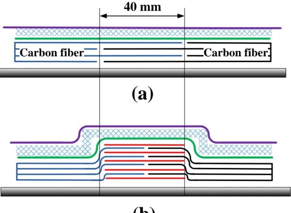
Laminated joint was made by stacking the two carbon fiber halves together and a joint length of 40 mm was made (see Figure 2.2a). Each carbon fiber layer was stacked in which one half is 40 mm longer than the other half. The second joint, multiple-covers, was made by stacking the two carbon fiber halves with equal length and inserting extra carbon fiber pieces between each layer in a structural manner similar to the sandwich structures (see Figure 2.2b). Four carbon fiber layers were used for all joints.
2.2.3. Manufacturing
All CFRP fabrics were produced using VARTM process. The entire process consist of three steps: constructing a vacuum package, infusing the resin and molding.
The structure of the vacuum package used in the experiment is shown in Figure 1.5a.
A solid mold, covered with a piece of peel ply, was used. Four layers of stitched unidirectional carbon-fiber fabric (from Saertex GmbH & Co. KG, the carbon fiber is TENAX STS, the stitching material is PES) with 30 cm in length were laid on the peel ply and then covered by another piece of peel ply. The horizontal direction of Figure 1.5a was the fiber direction. A small piece of distribution medium, a kind of mesh, was placed on the peel ply to promote the flow of resin.
The inlet for infusion, which was composed of a rubber connecter and a segment
of spiral tube, was positioned on the distribution medium. The vent for air and excess
resin elimination was positioned on the other side of the inlet. Both inlet and vent
were composed of a rubber connecter and a segment of spiral tube. Since inlet and
16
vent considered very critical points in the entire process they are tightly sealed by the sealant tape. Finally, the entire package was enclosed in a vacuum bag and sealed with tape. Figure 1.5b shows a picture of the adopted structure. After establishing a vacuum, degassed resin was infused from the inlet. After 40 min, the inlet was closed, and the vent was left open until the resin was cured. An epoxy resin that could be cured at room temperature (XNR/H 6815, supplied by Nagase & Co., Ltd.) was used in the experiment. The initial viscosity of the resin at 25
oC was 260 MPa s. When the resin was cured completely (about 24 h later), the CFRP laminate was removed from the mold. The thickness of the plate was about 2 mm.
2.2.4. Test procedures
Joint strength was evaluated via tensile testing using standardized test
specimens [27]. Figure 2.3 shows the dimensions of the specimens; the total length
was 250 mm and the width was 10 mm. Pairs of GFRP tabs were used to reduce the
stress when holding each specimen. All specimens are tested using SHIMADZU
DSS-5000 universal testing machine. Figure 2.4 shows the setup used for the current
tensile test. The specimen was fixed between the machine’s jaws, and the load-time
data was recorded through a load cell mounted on the upper jaw. A real time camera
connected to PC was mounted to record the deformation of the specimen during the
loading.
17
Distribution medium
Vacuum bag
80 mm
(a)
CFRP
Carbon fiber
Carbon fiber
Mold Peel ply
Mold Step 1
Step 2
Mold Distribution
medium Vacuum bag
80 mm Peel Ply
Carbon fiber
Step 1
Mold
(b)
CFRP
Carbon fiberStep 2
Figure 2.1: Joint group 1: (a) staircase joint-1, and (b) staircase joint-2
18
40 mm
(b) (a)
Carbon fiber Carbon fiber
Figure 2.2: Joint group 2: (a) laminated joint-1, (b) laminated joint-2, and (d) multi- overlapped joint.
Joint Tab
35 mm 50 mm
250 mm 40 or 80 mm 2 mm 2 mm
Figure 2.3: The standard specimen dimensions used for tensile testing
19
Figure 2.4: Tensile test setup for the current work
2.3. Results and discussions
The maximum tensile load was recorded as a measure of the joint’s mechanical performance. First, the tensile load of the jointless CFRP samples was measured, and used as a reference for the strength of subsequent joints. The jointless CFRP achieved a failure tensile load of 34 kN (See Figures 2.5 and 2.6), indicating that the tensile strength along the fiber direction was 1.7 GPa.
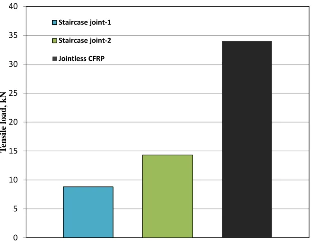
Figure 2.5 shows the maximum tensile load for joint type-1 samples. The lowest joint tensile strength recorded was for staircase joint-1, with a measured strength of 8.8 kN (26% joining efficiency). However, the strength of the other staircase joint, staircase joint-2 was significantly higher (14.3 kN; 42% joining efficiency). This is in agreement with previous studies that have suggested that joining carbon fabrics and CFRP fabrics results in low strength [27]. This behavior can be attributed to two factors. First, resin residue on the CFRP surface before joining can act as an insulator.
Second, the absence of overlap contact in these joints reduces the contact area,
resulting in a weaker joint [8]. On the other hand, staircase joint-2 achieved a much
21
higher strength than joint-1. This is attributed to the three fiber layers in that joint type that contact the CFRP part, three times more than the number of layers in joint-1.
Hence, joining dry carbon fabrics together resulted in generally higher strengths.
Figure 2.5: Maximum tensile load data of joint type-1 and jointless CFRP samples
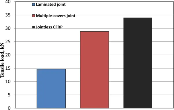
Figure 2.6 shows the maximum tensile load for joint type-2 samples, the laminated joint had a tensile strength similar to that of staircase joint-2, with a measured strength of 14.7 kN. This can be attributed to the absence of overlap contact between the two halves in laminated joint, which reduces the strength and promotes crack propagation near the joint ends. The introduction of overlap areas not only increases the contact area, but also increases joint thickness. On the other hand, the
0 5 10 15 20 25 30 35 40
Tensile load, kN
Staircase joint-1 Staircase joint-2 Jointless CFRP
21
remaining two joints were much stronger than the previous four joints. Multiple- covers joint had tensile load and joining efficiency of 28.8 kN and 85%, respectively.
This joint performed with the major difference being the greater thickness of the multiple-covers joint, which could be the reason for the higher observed strength.
Löbel et al. [8] constructed CFRP joints based on stainless pins, which resulted in a high joining efficiency of 83%. However, the metal-to-carbon fiber contact caused galvanic corrosion of the carbon fabrics, weakening the structure over time [42].
Figure 2.6: Maximum tensile load data of joint type-2 and jointless CFRP samples
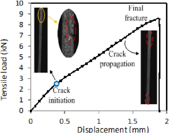
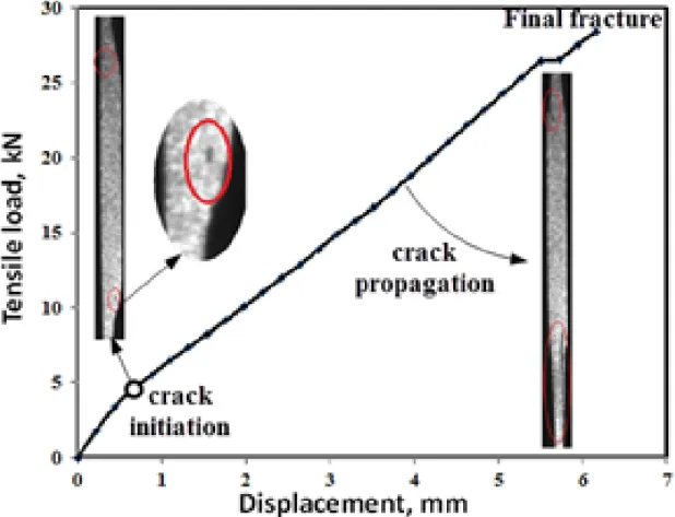
Figure 2.7 shows a typical tensile load-displacement diagram combined with images that show the deforming specimen of the staircase joint-1. In staircase joint-1, an initial crack occurred near the end of the joint, which reduced the gradient of the load-displacement curve. This resulted in a linear relationship between the tensile load
0 5 10 15 20 25 30 35 40
Tensile load, kN
Laminated joint Multiple-covers joint Jointless CFRP
22
and displacement. As the load increased, the crack size also increased until the specimen ultimately fractured. As noted, the initial cracking occurred at the end of the joint. This behavior can be explained as follows. In staircase joint-1, when joining the CFRP with carbon fabric, two separation lines were formed on both surface sides (Figure 2.8). These two lines were filled with resin after joining, and the crack initiated at these lines at the beginning of the tensile test. As the tensile load increases, the shear stress in the contact area increases and this causes relative motion between the CFRP portions. This leads to the enlargement of both separation lines and hence crack propagation.
The failure patterns were also investigated for other joint types. Figure 2.9 shows a typical tensile load-displacement diagram for Multiple-covers joint. Two cracks appeared near the joint ends, due to the accumulation of stress in these zones, which apparently caused a gradient change. Then the cracks propagated until specimen fracture. Figure 2.10 shows a schematic drawing of the multiple-covers joint. The possible zones of fracture are near the joint ends, where there is an accumulation off stress.
There are seven failure modes, including but not limited to the separation of the
interface between the adhesive and composite, de-lamination within the composite,
and a mixture of these two modes [43]. Micromechanical investigations have revealed
different dominant failure modes under tensile and shear loads [36]. In addition, the
strength of the interface between the adhesive and composite at a joint is a key factor
determining the failure mode and the strength of a structure. In the present study, both
staircase joints 1 and 2 showed separation of the interface, whereas joint group 2
showed a mixture of failure modes.
23
Figure 2.7: A diagram of typical tensile load-displacement, with images for staircase joint-1.
CFRP
Separation lines filled with resin
Contact area filled with resin
CFRP
Figure 2.8: Schematic drawing of a staircase joint after bonding
24
Figure 2. 9: Typical tensile load-displacement diagram with images for a multiple- covers joint
Figure 2.10: Schematic drawing of a multiple-covers joint with possible crack zones highlighted
2.4. Conclusions
Four adhesive joints were designed and fabricated using VARTM manufacturing
process. The tensile test results showed low strength when one half of the joint is
CFRP fabrics, which was the case for the first two developed joints, staircase joint-1
25
and staircase joint-2. In these joints, it was investigated that the residue resin on the CFRP half’s surface worked as insulator, and hence the shear strength along the interface was reduced. On the other hand, multiple-covers joint, showed higher tensile strength. However, joining techniques that use dry carbon fibers are still limited for simple shapes, so there are some difficulties for applying these techniques for complex curved shapes like wind blades and lens as well.
To sum up, type 1 joints are weaker, longer fabrication time. But, it’s more
practical and can be used to join complex shapes. In contrast, type 2 joints are
stronger, shorter fabrication time, but it’s more complex. Therefore, both joint types
should be considered for the future improvements.
26
Chapter 3
Effect of stitching on the tensile strength of the current novel joints CFRP adhesive joints
3.1. Introduction
In chapter 2, two CFRP adhesive joint types were introduced. Joint type 1, which is constructed between CFRP fabric and dry carbon fibers halves. This joint was represented by two staircase joints named staircase-1 and staircase-2. Joint type 2 is fabricated by stacking two dry carbon fibers halves. This joint represented by two joints called laminated and multiple-covers joints. Compared to joint type 1, joint type 2 was stronger and shorter fabrication time. However, joint type 1 is more practical and less complex. Therefore, when applying further improvements, both joint types should be considered.
In CFRP composite structures, joints are crucial load-carrying elements, and the mechanical performance of the whole structure depends on the joining efficiency. In other words, the strength of the CFRP composite structure is equal to the strength of its joint. Therefore the improvement of CFRP adhesive joints is very crucial. There remains significant scope for improvement in the strength and durability of bonded joints [8]. Stitching is considered to be an effective method of forming strong bonded composite joints [8], and Hes et al. [44] and Dransfield et al. [45] showed that this technique could enhance the fracture toughness of composites under peel load conditions.
This chapter studies the effect of stitching on both CFRP joint types, which
introduced in chapter 2. The stitching technique will be applied for two joints, staircas
27
e joint-2 and multiple-covers joint. For the staircase joint-2, the original staircase joint -2 was put in comparison with the adjusted one. The adjustment was applied by stitching with carbon fiber bundles (see Figure 3.1 a-c). Similarly for multiple-covers joint, its original form was put in comparison with its stitched form (see Figure 3.2 a- c).
3.2. Experimental Methods
3.2.1. Materials
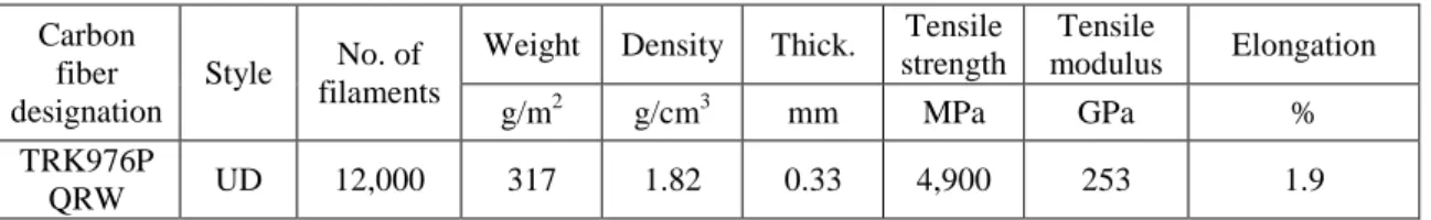
The CFRP composites consisted of carbon fabric and a resin mixture. The resin was a mixture of XNR6815 and XNH6815 at a weight ratio of 100:27. The resin mixture viscosity at 25°C was 260 mPa.s. The carbon fiber used for this work was made by Mitsubishi Rayon Co. LTD. Table 3.1 introduces the characteristics for this carbon fiber. Five unidirectional carbon fabric layers were stacked and molded together to form 1.5-mm-thick plates.
Table 3.1: Characteristics of the carbon fiber used in this work
Carbon fiber designation
Style No. of filaments
Weight Density Thick. Tensile strength
Tensile
modulus Elongation
g/m2 g/cm3 mm MPa GPa %
TRK976P
QRW UD 12,000 317 1.82 0.33 4,900 253 1.9
3.2.2. Adhesive joints
Two different types of joint were used with the stitching technique. One joint was
constructed using dry carbon fiber fabric and CFRP. A stepped CFRP fabric was
manufactured first, which was then re-molded with dry carbon fiber fabric. This joint
is called staircase joint. Figure 3.1a shows a schematic top view of the VARTM mold
for all staircase joints. Figure 3.1b shows the original staircase joint. The stitching was
28
applied perpendicularly through both CFRP and dry carbon fibers halves using carbon fiber bundles. The stitches compose a matrix in which its rows are in the fiber direction (resin flow direction), and the columns are in the other perpendicular, see Figure 3.1a. The stitch length is 8 mm, and the distance between columns is 10 mm, see Figure 3.1c.
The other joint type was constructed using two dry carbon fiber halves. With this joint, two five-layer carbon fiber sheets were stacked. This joint is termed multiple- covers joint. Figure 3.2a shows a schematic top view of the VARTM mold for all multiple-covers joints. The original form for this joint is shown in Figure 3.2b. In this joint, the separation between the two mated carbon layers was covered using two 40- mm-wide carbon fiber pieces. The second form for multiple-covers joint is shown in Figure 3.2c. With this joint, we used stitching with carbon bundles of the same carbon fiber type, which were applied perpendicular to the plane of the laminate [44-45]. All joints were formed using a single VARTM process.
3.2.3. Manufacturing
All CFRPs’ parts were formed using VARTM, which is a variation of the resin
transfer molding (RTM) technique, in which a solid mold with a flexible tape-sealed
vacuum bag is used instead of a closed mold. In the VARTM process, reinforcements
are stacked on a solid mold, which is treated with a mold-releasing agent and covered
with a peel-ply and a distribution medium. These are enclosed in a vacuum bag,
which has an inlet and a vent, and which is sealed using gum tape, as shown in Figure
3.3.
29
Carbon fiber
Vacuum bag Sealant tape Infusion mesh
Carbon fiber cover
CFRP
Vent
A
B
Mold
80 mm Peel ply
CFRP
Carbon fiber stitching bundles 40 mm
Carbon fiber
Infusion mesh Vacuum bag
(c) (b)
10 mm10 mm
8 mm stitches (a)
Inlet
SEC A-A
SEC B-B
A
B
Figure 3. 1: (a) Schematic top view of the staircase joints: (b) original staircase and (c) stitched staircase joints
3.2.4. Test procedures
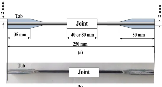
The strength of the joints was evaluated via tensile testing using standardized test
specimens [27]. Figure 3.4a shows the dimensions of the specimens; the total length
was 250 mm and the width was 10 mm. Pairs of CFRP tabs were used to reduce the
stress when holding each specimen, as shown in Figure 3.4b.
31
Carbon fiber
Vacuum bag Sealant tape Peel ply Infusion mesh
Carbon fiber covers
A A
B B
Carbon fiber
Connecting carbon fabric pieces
Stitching carbon bundles
Vacuum bag Infusion mesh
Peel ply
(b)
(c)
Carbon fiber Carbon fiber
Carbon fiber Carbon fiber
10 mm 15 mm 10 mm 8 mm stitches
SEC A-A
SEC B-B
(a)
Figure.3. 2: (a) Schematic top view of all multiple-covers joints (b) original multiple-covers, and (c) stitched multiple-covers joints
Inlet
Sealant Resin Mold Peel ply Vacuum bag Fabric
Infusion mesh
Vacuum
Vacuum chamber Pressure sensor Vent
Figure.3. 3: Schematic diagram of the VARTM process used in this work
31
Joint
Tab
35 mm 50 mm
250 mm 40 or 80 mm
2 mm 2 mm
Tab
Joint
(a)
(b)
Figure 3. 4: Standard specimen dimensions used for tensile testing and (b) an image of a specimen used in a tensile test
3.3. Results and Discussions
All tests were carried out according to the ASTM standard D3039/D3039M, with a constant crosshead speed of 2 mm/min at a room temperature (i.e., 23ºC). The tensile tests were performed at least three times and the average value of the three measurement values was used as representative. The results showed a maximum error of 15%. Figure 3.5 shows the tensile load of the multiple-covers joint in both original and stitched forms. The tensile load of the original CFRP without joint is also indicated in the figure as the maximum value that logically all joints cannot exceed.
The load of the unstitched multiple-covers joint was 17.2 kN, and that of the stitched
multiple-covers joint was 20.8 kN (i.e., 21% stronger). This can be attributed to two
factors. First, the use of additional carbon bundles results in an increase in the average
thickness of the joint. Second, the stitching direction was perpendicular to the
32
laminate, so that it functions as an additional carbon lamina, forming a bidirectional composite.
Figure 3.6 shows the tensile load of all staircase joints combined with vertical error bars. The strength of the staircase joint was only 9.5 kN. This is consistent with previous studies showing that joining carbon fabrics and CFRP fabrics results in low- strength joints [26]. This can be attributed to two factors. First, resin residue on the CFRP surface prior to joining can act as an insulator. Second, the absence of overlap in these joints reduced the contact area, resulting in a weaker joint [8].
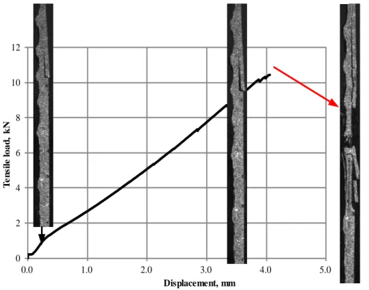
Figure 3.7 shows a typical tensile load–displacement curve combined with images that show the original staircase joint at various stages of the test. An initial crack occurred near the end of the joint, which reduced the gradient of the load–
displacement curve. This resulted in a linear relationship between the tensile load and the displacement. As the load increased, the crack grew, until the specimen fractured.
The initial crack occurred at the end of the joint. This can be explained as follows.
When joining the CFRP with the carbon fabric, two separation lines were formed on the two surfaces of the part. These two lines were filled with resin after joining, and the crack initiated at these lines. As the tensile load increased, the shear stress in the contact area increased, which caused relative motion between the two CFRP portions, and led to enlargement of both separation lines, and hence crack propagation.
On the other hand, stitched staircase joint achieved a small increase in the
strength. The tensile load of the stitched staircase joint was 9% higher than that of the
original staircase joint. However, it is believed that this increase was caused by
addition of two carbon fiber pieces near the joint ends. These two pieces were put
33
before applying the stitching to cover the gaps at the joint ends. Oppositely, the fracture analysis shows a weakened structure because of stitching. First, the stitches over the CFRP fabric result in gaps between the mold and the CFRP part, as shown in Figure 3.8a. These gaps were filled with resin during molding. In addition, due to the position of these gaps, it was difficult to remove voids in the resin that filled the gaps (see Figure 3.8b). Second, stitching produced notches in the CFRP part, which weakened the structure after molding. LÖbel et al. [8] showed that the existence of holes in CFRP fabrics results in peaking the stress around these holes, and hence a weaker CFRP structure. Figure 3.9 shows a typical tensile load–displacement curve, combined with images that show the deformed stitched staircase joint at various stages of the test. The crack initiated and propagated at the end of the joint, yet the specimen failed at the location of the notches caused by stitching.
Figure 3. 5: Tensile loads of the two multiple-covers joints
17.2
20.8
26
0 5 10 15 20 25 30
Multiple-covers joint Stitched multiple-covers joint
Jointless CFRP
Maximum tensile load, kN
Maximum tensile load
34
Figure 3.6: Tensile loads of the staircase joints
Figure 3.7: Typical tensile load–displacement curve, with images of the staircase joint at different stages of the test
9.5 10.4
26
0 5 10 15 20 25 30
Staircase joint Stitched staircase joint Jointless CFRP
Maximum tensile looad, kN
Maximum tensile load
![Figure 1.1: Wind power turbine system with a diffuser designed by Kyushu University [3]](https://thumb-ap.123doks.com/thumbv2/123deta/9918769.1919817/18.892.159.737.641.1006/figure-wind-power-turbine-diffuser-designed-kyushu-university.webp)