INVITED PAPER Special Section on Network Resource Control and Management for IoT Services and Applications
Resource Management Architecture of Metro Aggregation Network for IoT Traffic
Akira MISAWA†a),Senior Member andMasaru KATAYAMA††,Member
SUMMARY IoT (Internet of Things) services are emerging and the bandwidth requirements for rich media communication services are in- creasing exponentially. We propose a virtual edge architecture comprising computation resource management layers and path bandwidth management layers for easy addition and reallocation of new service node functions.
These functions are performed by the Virtualized Network Function (VNF), which accommodates terminals covering a corresponding access node to realize fast VNF migration. To increase network size for IoT traffic, VNF migration is limited to the VNF that contains the active terminals, which leads to a 20% reduction in the computation of VNF migration. Fast dy- namic bandwidth allocation for dynamic bandwidth paths is realized by proposed Hierarchical Time Slot Allocation of Optical Layer 2 Switch Net- work, which attain the minimum calculation time of less than 1/100.
key words: network virtualization, passive optical network, optical switch- ing, optical subwavelength switched network, time-slot allocation, dynamic bandwidth re-optimization, WDM/TDM
1. Introduction
Internet traffic has been increasing due to the rapid pene- tration of broadband access technologies[1]. In Japan, the number of subscribers to broadband services like FTTH and ADSL now exceeds 36 million. The required bandwidth for each person is growing due to the penetration of the higher- definition and higher-resolution Internet video services. The rich contents of applications accessible through broadband or mobile, require higher network bandwidths, especially in metro aggregation networks where the traffic from many ac- cess networks is being channeled into network edge service nodes.
In addition to conventional internet applications, re- cent IoT services are increasing rapidly, and this has led to growing concern over how to manage massive data traffic effectively. IoT services are widely distributed among appli- cations including connected cars, smart homes, and sensor networks from LPWA (Low Power, Wide Area) terminals [2]or wearable terminals[3]. This makes it difficult to an- ticipate what kind of IoT services will develop and how large traffic volumes will grow in the future[4].
A range of application traffic from terminals via the access nodes such as mobile radio stations and optical ac-
Manuscript received June 8, 2017.
Manuscript revised August 16, 2017.
Manuscript publicized September 19, 2017.
†The author is with Chitose Institute of Science and Technol- ogy, Chitose-shi, 066-8655 Japan.
††The author is with NTT Network Service Systems Laborato- ries, NTT Corporation, Musashino-shi, 180-8585 Japan.
a) E-mail: [email protected] DOI: 10.1587/transcom.2017NRI0002
cess nodes should be aggregated geographically and line- concentrated into the service edge nodes. The edge node classifies mixed flows to its application flows such as Inter- net access, IP telephony, VoD, and IoT services according to the service subscription of the layer 3 and layer 4 (L3/L4) information in the packet. Then service admission con- trols, session controls between terminals and edge nodes, and processing determined by services like address transla- tion, remark of priority control fields, and protocol change are deployed on the fly and finally transferred to the appro- priate destinations. This is why high performance is required for edge nodes[5].
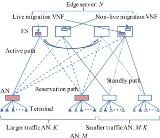
Figure 1 shows a schematic metro aggregation network for fixed-line service networks and mobile networks. Con- ventional aggregation networks have simple tree structures from particular access nodes to the dedicated edge nodes via electrical packet switches like Ether switches, and these are connected by point-to-point optical paths of wavelength ring networks. Therefore, computational and bandwidth re- sources among edge nodes and packet switches cannot be shared and resource shortage might occur even if a neigh- boring edge node and packet switch has excess resources.
Sufficient resources should be used for all the network ele- ments during peak usage. Moreover, fixed and mobile net- works are independent while network equipment like edge nodes are different. WDM ring equipment can be shared among mobile and fixed networks but bandwidth resource cannot be shared.
Because the cost of access networks and metro aggrega- tion networks account for most of the carrier networks costs, effective network resource utilization is very important. IoT uses various types of terminal, and both access networks
Fig. 1 Schematics of conventional metro aggregation network.
Copyright © 2018 The Institute of Electronics, Information and Communication Engineers
for mobile and broadband optical access like PON (Passive Optical Network) should be used freely depending on the application use. To increase network size for IoT traffic, net- work management needs to be improved for dynamic traffic change by IoT.
This paper is organized as follows. In Sect. 2, we de- scribe the traffic requirement for the emerging IoT applica- tions and services. We previously proposed a virtual edge architecture for edge nodes and variable bandwidth path mechanism for connection paths. Proposed virtual edge ar- chitecture with variable bandwidth path mechanism for fixed and mobile convergence network is described. In Sect. 3, we describe scalable virtual edge management efficiently to save the server resources. In Sect. 4, the fast dynamic bandwidth allocation algorithm is described.
2. The Impact of IoT Services on Future Networks
2.1 Traffic Characteristics of IoT Services
It was a difficult matter to analyze traffic and predict the traffic patterns and volumes. Conventional IP telephony involves simple 64 kbit/s-packet flows and the duration of almost all holding calls is several minutes. However, there are various traffic flow inputs into the networks owing to media richness and emerging applications. Table 1 shows the characteris- tics of application flows. Transfer speed varies according to Codec in real-time communication through such means as high-quality video conference services, so it is becoming dif- ficult to predict the band demand on the network. Recently, band-eating video streaming and Video on demand services have grown popular. In the future, IoT services will be widely distributed, though the network requirements might differ for each service, as shown in Table 1. For example, among sensing applications, the number of sensor terminals can be huge and data traffic tends to flow intermittently, in bursts. In machine-to-machine control areas like connected car services, the roundtrip time is severe, so low latency is required.
For an example of a sensor network, we will discuss the relationship between the incoming traffic volume and the required network resources. The number of terminals of the sensor application is far larger and the terminals have more bursty traffic characteristics than in conventional communi- cation services. For the total number of sensor terminals connected to an edge node denoted as N, the utilization ratio of sending traffic and generated traffic bandwidth for each terminal are assumed to be uniform and denoted as ρandb, respectively. The total network resource demand for the terminal is a binominal distributionB(bN, ρ) at an average of bNρ. The computational resource at the edge node should be designed to treat the satiation where traffic is more concentrated than conventional traffic. When edge resources are designed to allow incoming traffic of more than 99%, that is the cumulative binominal distribution of P(bN <bN0)>0.99, the relationship between average traf- fic volume ofbNρand required resourcebN0 is as shown
Table 1 Characteristics of application flows.
Fig. 2 Required node resource to allow incoming traffic over 99%.
in Fig. 2, where the required resource at the edge node is assumed to be proportional to bandwidth demands.
With a greater number of terminals at the edge node, the required resource is growing closer to that of average traf- fic by scale effect. When the number of terminals reaches 500, the required resource is 1.2 times greater than that of average traffic. The smaller the utilization ratio at the termi- nal, the more node resources are required. This indicates that node processing efficiency diminishes due to intermittent and bursty traffic from terminals like IoT sensor applications, and greater volumes of terminal traffic should be concentered in a node.
To take another example, for connected-car applica- tions, response time requirements are very high. In the conventional wavelength-routed metro aggregation network architecture [6], the light paths are generally managed on longer timescales, and most operations are executed accord- ing to predetermined plans. However, metro aggregation networks meet several requirements such as the variable bandwidth demand shown in Table 1. The requirements for connected-car traffic, especially, reach the maximum of a 50 msec delay-budget. Therefore, metro aggregation network architecture for IoT traffic should adapt to shorter-timescale traffic fluctuations and achieve flexible resource utilization.
To address this issue, we previously proposed an optical sub- wavelength switched network architecture called the optical layer-2 switch network (OL2SW-NW) that can efficiently ac- commodate dynamic traffic in metro aggregation networks
[7].
2.2 Network Control of the Virtual Edge and Variable Bandwidth Paths for IoT Traffic
Owing to various IoT services as well as the conventional In- ternet services, network service admission controls deployed intensively at the carrier network edge are getting compli- cated because charging and security management is different for each of the service traffic flows and sessions[5]. The net- work edge concentrates and manages large traffic volumes and flows, so larger capacities and computational resources are required for the carrier network edge terminals.
Network function virtualization (NFV)[8]has attracted the attention of carrier networks. Network function virtu- alization of routers and switches in a conventional carrier network is expected to reduce costs through the efficient use of hardware resources and the reduction of development time and service delivery latency in accordance with user needs by adding or changing virtual functions.
We previously proposed virtual edge architecture with virtualized network functions (VNFs) in edge servers (ESs) instead of dedicated edge routers[9]. The live migration of VNFs is valuable for efficient resource use. We also pro- posed the Optical Layer 2 Switch Network (OL2SW-NW) [7]which is an expansion of dynamic bandwidth allocation [10]for multi-point to multi-point network. Moreover, we proposed virtual edge architecture that combines VNFs and OL2SW-NW for fixed network using the PON access net- work.
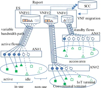
Figure 3 shows a physical schematic of the proposed architecture with the OL2SW-NW for gathering traffic from access nodes (ANs) into ESs and then sending the traffic to the core backbone via a gateway router (GW). ANs are optical line terminals (OLTs) of a 10GE-PON[11]for op- tical access networks and mobile stations for radio access networks. VNFs for 10GE-PON and mobiles have differ- ent functions but ESs can be shared by both VNFs. These are locally located to gather traffic from a variety of termi- nals. Packet flows between ESs and ANs are transmitted via variable bandwidth paths. VNFs in ESs are used instead of dedicated edge nodes in the conventional metro aggregation network. The service computation controller (SCC) man- ages ES resources and the allocation of VNFs to the ESs, and the SCC simultaneously allocates the position of ESs for live migration and recovery to each active VNF. It de- termines the correspondence of active and potential paths.
The live migration of VNFs is performed when a shortage of computational resources occurs in ESs due to peak service usage.
With the OL2SW-NW, the ring bandwidth can be shared among all service flows that go through potential paths to save optical network resources and bandwidth capacity. The band manager (BM) of OL2SW-NW manages forwarding control and bandwidth allocation for the entire path. Fast bandwidth allocation for all service flows is performed to guarantee service quality. The burst senders and receivers
Fig. 3 Proposed virtual edge architecture with OL2SW-NW.
(BSRs) of the ESs and OLTs work as a converter from the packets to optical WDM/TDM time-slot signals, i.e., burst signals[12]. They contain wavelength tunable lasers to send a variable bandwidth path using wavelength/time-slot sig- nals. The number of wavelength paths determines the total capacity of the OL2SW-NW.
3. Scalable VNF Management Architecture
3.1 Live Migration of theKth-Largest-Terminals VNFs For IoT era networks, the number of control entities is large, and rapid management of VNF resource and path reroutes in SCC is becoming increasingly important. End-to-end band- width resource conformation for service flows in a variable bandwidth path should be considered throughout a metro aggregation network. Even though live migration of VNFs is effective for saving server processor resources, it might lead to service interruption and bandwidth shortage of ser- vice flows, so, when the live migration of VNFs occurs, fast rerouting of the paths between ESs and ANs is required.
During this reroute, the service flow should be transmitted without service session interruption.
To ensure the fast reroute of paths, VNFs have a one-to- one correspondence to the dedicated AN, which is the first feature of this architecture. Figure 4 shows a schematic of the logical configuration between VNFs and ANs. The total number of VNFs is equal to the number of ANs. The path of an AN is connected only to the corresponding VNF. The ESs contain several VNFs, but the path is a simple point-to-point one. From the viewpoint of ESs, a simple star topology is constructed between ANs. This simple correspondence reduces the complicated mapping control between VNFs and ANs. The notification from SCC to BM of live migration
Fig. 4 Schematic of proposed virtual edge logical architecture.
also becomes simple because the active paths correspond to in-use flows. Owing to this feature, the volume of a VNF is relatively small because an AN contains a relatively small number of terminals. Therefore, a small-volume VNF can lead to in-service live migration due to short migration time [13].
The resource demand of a VNF depends on the num- ber of active terminals connected to an AN, which varies according to terminal participation and withdrawing. This VNF resource demand also varies according to various ser- vice usages and changes rapidly based on service-usage du- ration. The physical ES resources of a CPU and network interface card (NIC) are divided into a virtual CPU (vCPU) and virtual NIC (vNIC) to enable each VNF to use these re- sources efficiently. If demand exceeds the physical resources of bandwidth and processor in the ES and resource shortage occurs due to peak service usage, some of the VNFs are live-migrated to another ES that has excess resources.
There are still scalability problems due to the large number of VNFs. The important point is which VNFs should move. The second feature of this architecture is that only VNFs containing many active terminals can be live-migration candidates because considering all VNFs as candidates would create excessive demands on the proces- sor and bandwidth resources. The number of VNFs where live-migration is permitted is denoted as K. If all VNFs are candidates for live migration, the live-migration control requires a large amount of computation time or resources which is proportional to the number of live-migration can- didate VNF. This number, which is equal to the number of ANs, is huge. The live migration VNF candidates are rese- lected in order of larger-active-terminals when the number of active terminals varies according to joining and withdrawal.
Server resource reallocation is performed within an internal ES and then the resource allocations of vCPUs and vNICs are changed.
3.2 Live Migration VNF Selection for PON Network In previous work in Ref.[9], we considered AN to be an optical fixed line access node like the optical line terminals (OLT) of 10G-EPON and terminals to be PCs and tablets for Internet applications. In this case, the candidates for live VNF migration are selected in descending order of the number of subscribers. A 10GE-PON can accommodate up to 32 subscribers, which is the maximum branch, so the number of field 10GE-PON subscribers is distributed from 0 and 32. The change of subscriber numbers is slow on a daily basis only due to participation and withdrawal of network service. The required demand of computation and bandwidth from VNF to ES varies by service usage of subscriber terminals. Major applications are Web browsing, VoD, and streaming, so traffic is relatively large and of long duration. The number of subscribers is strongly related to the network resource demand of VNFs.
For evaluation of live migration: in a metro aggrega- tion network, the number of ESs that have 10-Gbit/s network interface cards (NICs) is N =100 and the number of ANs is M = 2500, so, ES has 25 VNFs on average. In the case of 10GE-PON for AN[9], we assumed that the aver- age number of subscribers in a 10GE-PON is 16, so this network contains a total of 40,000 subscribers. The distribu- tion of subscribers in VNFs, which have same distribution as OLTs, is uniform and binominal. For uniform distribu- tion, the number of VNFs is the same from 0 to 32, that is M/33 ; 75. For binominal distribution, the maximum number of VNFs is 350 for 16 subscribers. As shown in Fig. 5, the accumulated number of subscribers of the largest 500 VNFs is more than a quarter of all subscribers. If the largest 500 VNFs are selected, the number of live-migration subscribers is 10,000 and 14,000 for binominal and uniform distributions, respectively.
Next, we will discuss the volume of paths connecting ANs and VNFs. All ANs should have at least two logical paths for failure recovery of the ES and OL2SW-NW. The control management path is complicated further by the large number of recovery paths. ANs up to the Kth largest have one active path to the ES that contains the corresponding VNFs and the N−1 =99 potential paths to the other ESs for live migration, and potential paths serve as the standby paths for failure recovery. The rest of the M −K ANs have only two logical paths, one each for the active path and standby path for failure recovery. The total number of logical paths is K N +2(M −K) = 54,000, which is less than the case in which all VNFs are candidates for live mi- gration, that isK=2500, making the total number of logical pathsN M=250,000. Compared with these cases, limiting K-th VNF migration leads to a 20% (=500/2500) reduction in the SCC computation of VNF migration and a 21.6%
(=54,000/250,000) reduction in the BM computation of log- ical paths, as listed in Table 2.
Considering the case of mobile access for ANs, smart- phones are mainly used for Internet access in the same way
Fig. 5 Accumulation of subscribers in VNFs.
Table 2 Effect of reduction on VNFs and paths to be managed.
as terminals in the 10GE-PON, so the VNF selection in the order of largest terminals is effective. However, the numbers of mobile terminals in a mobile access area changes rapidly and frequently due to the movement of users, so, SCC should gather the number of the active mobile terminals from VNFs and reselect the candidate VNFs for live migration. Though VNFs for mobile and VNFs for 10GE-PON are different in the function of session control protocol and service admis- sion control, two types of these VNFs can be shared among the same ESs resources in the same management of K-th largest VNF migration by SCC.
3.3 Live Migration VNF Selection for IoT Network In this paper, we consider the various types of ANs and application terminals for IoT. For example, it should be con- sidered that some IoT terminals are connected both by the mobile network and the 10G-EPON network. In such cases, it is hard to determine which VNFs should be selected for live migration. The IoT traffic characteristics of bandwidth and holding time depend on applications and are far from the conventional Internet communication traffic as described in Sect. 2.1, so, simple subscriber order selection for the live migration VNF is not adequate. The sensing application and a huge number of terminals exist in an access area but the to- tal required bandwidth is very small and intermittent. When the conventional and IoT terminals are mixed in a metro ag- gregation network, the total number of terminals does not always relate to the resource demand.
To solve these issues, we propose the method of weighted terminal numbers and usage bandwidth for live- migration VNF selection. Figure 6 shows the schematics of
Fig. 6 Schematics of active flows and idle flows.
terminal states. The square and triangle denote conventional and IoT terminals, respectively. The states of terminals are in-use or non-use. In-use denotes that the network recog- nizes the terminal by negotiation protocol for the identifica- tion of a terminal and the user. For the VNFs and ANs, the number of in-use terminals is countable by the connection kept by session control protocol. Application service traffic is transmitted using this connection flow. The active or idle status of the terminals determines whether application traf- fic exists or not, and required bandwidth and computational resource are mainly used by flows of the active terminals at any given moment. The greater the number of in-use termi- nals, the larger the required resource change, so, basically a VNF containing a lot of in-use terminals should be selected for live-migration. However, the required bandwidth differs depending on application flows and it is hard for the SCC to check which application is used for all the flows.
For simple and fast SCC control, only two parameters of the number of in-use terminals and path bandwidth are used to solve the VNF selection. We assume that the num- ber of conventional and IoT services can be countable by the service description of packet headers or session control pro- tocols. First, VNFs with larger numbers of in-use terminals at more than threshold value are candidates for live migra- tion. Next, the SCC calculates the weighed in-use terminals in each VNF by bconvNconv+bIoTNIoT, whereb, N, is the average bandwidth and the number of in-use terminals of the conventional and IoT terminals, respectively, then theK-th largest VNFs are selected. Because the path bandwidth of each VNF and the numbers of in-use conventional and IoT terminals are periodically reported, the average bandwidths bconv and bIoT can be statistically estimated. Practically, weight value should be adjusted by traffic characteristics and simple calculation is required because there are huge num- bers of terminals in IoT networks and the number of in-use terminal changes frequently.
4. Fast Dynamic Bandwidth Allocation Control For the IoT era network, a dynamic bandwidth allocation algorithm [14],[15] in BM should also be faster. Corre- sponding to shorter-timescale traffic fluctuation with shorter delays, we will introduce the concept of “hierarchical” Time Slot Allocation (TSA) calculation for variable bandwidth path mechanism. We will first point out the problem with conventional TSA methods that use network-wide informa- tion and aim to attain better network performance, then we will propose our fast TSA method and explain how it works.
A fundamental problem that occurs with conventional TSA methods is the enormously increased calculation time re- sulting from the larger number of access nodes in metro aggregation networks. This means that the calculation time of conventional methods typically depends on the product of the number of paths and the number of links in the network because conventional methods search sequentially for ade- quate time slots considering certain criteria in each travers- ing link of each path to ensure the exclusiveness of the al- located time slots. To solve these problems, we introduce hierarchical calculation to TSA processing and divide large- scale network-wide TSA into small-scale local TSAs. Then we calculate several small-scale TSAs independently, which leads to a reduction in computation cost and calculation time.
A rough outline of the proposed method in an 8-node ring network is shown in Fig. 7, which is an example showing the setups of four node groups. First, we define a set of some adjacent nodes as a node group in a well-known first-fit manner to achieve a TSA hierarchy. Each node will belong to only one node group. We call an ordered pair of node groups a node-group pair (GP). Then we compute a TSA for paths in each GP (inner-GP TSA) and a TSA for GPs (inter- GP TSA). Inner-GP TSA is applied to a well-known first-fit algorithm. Then, in descending order of path length (the tie is broken randomly), the vacant TS(s) is (are) searched from lower-numbered slots to higher ones, and the first TS(s) is (are) selected. This algorithm has a low computation cost since global information is not required.
Inner-GP TSA determines the required amount of TS/wavelength resources for each GP. Inter-GP TSA plays an important arbitration role between all GPs, so this TSA requires a lower computation time algorithm while achiev-
Fig. 7 Schematic of proposed time-slot allocation method.
ing dense packing of TSs. To emphasize the computation cost, we apply a first-fit algorithm similar to that of an inner-GP TSA. In descending order of the number of links traversed by paths of the intended GP, the vacant TS re- sources are searched from the lower-numbered slots of the lower-numbered wavelength on the node-group layer topol- ogy. Therefore, the number of TSA objects, GPs, and links in the node-group layer increase along with the number of node groups. Thus, the number of groups must be adjusted to attain better performance. With a first-fit algorithm, al- located TSs are packed towards the lower-numbered slots of the TS schedule with lower computation time.
Finally, we obtain a time-slot schedule by matching the results of the inner-GP TSA to that of the inter-GP TSA. In this process, all paths in the node-layer NW are classified uniquely into a GP. This classification and the inter-GP TSA enable us to ensure the exclusiveness of TS allocation. In fact, the inter-GP TSA plays an important arbitration role between all GPs; meanwhile, there may be some concerns that rough-grained allocation at inter-GP TSA will cause lower link utilization.
We evaluated the TSA characteristics of the proposed method and a conventional TSA method [16]. The con- ventional method using a first-fit time-slot assignment al- gorithm searches sequentially for adequate time slots in a well-known first-fit manner in each traversing link of every path. Therefore, the time complexity of the conventional method TC(Conv.), which depends on the product of the number of pathsO(N2)and the number of linksO(N)in the network, is approximately expressed as
TC(Conv.)=O(N3). (1)
On the other hand, the proposed method divides the network-wide problem into several small-scale problems (inner-GP TSAs and inter-GP TSA). First, node-grouping requires only simple calculations and its computation cost is sufficiently lower than inner-GP TSAs and inter-GP TSA. We now focus on these TSAs. The number of nodes belonging to each group isO(N/G)when the nodes are divided equally into each group. In the same way, the number of paths be- longing to each GP isO{(N/G)2}. Then, we can identify GPs as 2 types; one is an ordered pair of groups whose members are in the same group, GPsame, and the other is one whose members are from different groups, GPdiff. The paths that belong to the former connect two nodes that are members of the same node group. The others connect two nodes that belong to different node groups. The time com- plexity of inner-GP TSA in GPsame, TC(inner-GPsame) is approximately expressed as
TC(inner-GPsame)=O{(N/G)3}G, (2)
because the number of paths that belong to same node group is O{(N/G)2}, the number of links is O(N/G), and the number ofGPsame isG. The time complexity of inner-GP TSA in GPdiff,TC(inner-GPdiff)is approximately expressed as
TC(inner-GP)diff)=O{(N/G)2}G(G−1) (3) because paths in the same GPdiff must traverse a certain common link and contention avoidance must be considered on one link, and the number ofGPdiff isG(G−1). On the other hand, the time complexity of inter-GP TSA,TC(inter- GP), is approximately expressed as
TC(inter-GP)=O(G3). (4)
Therefore, the total time complexity of proposed method, TC(proposed), is approximately expressed as
TC(proposed)=O{G3+N(N/G)2+N2}. (5) By differentiating equation (5) withG, it is found that the minimum time complexity setting Gto be the integer (e.g. a power of 2) is around N3/5. Thus,TC(proposed)is O(N2). Therefore, the computation cost of the proposed method can be greatly reduced compared to that of the con- ventional method. Moreover, the hierarchical calculation is more effective in larger-scale networks (largerN).
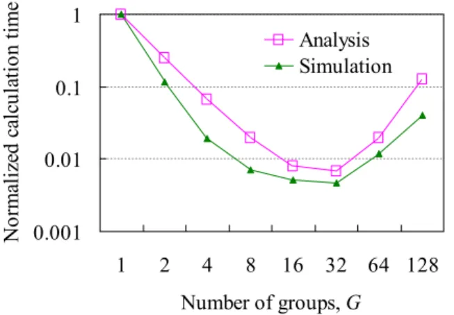
We evaluated the performance of the proposed method in terms of reducing calculation time and suppressing degra- dation of allocation performance for a simple full-mesh net- work. First, the calculation time of the proposed method normalized by that of the conventional method, which uses a well-known first-fit algorithm in a 256-node (about 65K- paths) network, is shown in Fig. 8, whereG=1 represents the conventional method. The results of theoretical anal- ysis and computer simulation have the same tendency and we clarified that the proposed method can reduce calcula- tion time by two orders of magnitude. We also verified that
“settingGto the integer around N3/5” can attain the mini- mum calculation time (when N is 256,Gshould be set to 32) of less than 1/100. In addition, we focus only on the paths in which allocation needs to be changed. In our pro- posed method, instead of reducing the computation time, allocation performance in terms of the schedule length of TSA decreases. We evaluated the allocation performance by computer simulation. Our proposed method can suppress the increase in schedule length to within around 10% of the
Fig. 8 Reduction in TSA calculation time in full-mesh, 256-node ring network model.
optimal solution, which is derived from the conventional method.
5. Conclusion
We proposed a virtual edge architecture using the OL2SW- NW, which exploits a WDM/TDM ring topology and is adopted for metro aggregation networks to save bandwidth resources while providing fast control for large-volume traf- fic of the IoT applications. In this architecture, a VNF cor- responds to a particular access node, and the migration of a VNF is limited to the K-th VNFs that contains a larger number of subscribers. This feature results in a reduction in the total number of variable bandwidth paths, enabling high-speed TSA control. This limitingK-th VNF migration leads to a 20% (=500/2500) reduction in the computation of VNF migration and a 21.6% (=54,000/250,000) reduction in the bandwidth management computation of logical paths.
In addition, corresponding to shorter-timescale traffic fluctuation with shorter delays, we proposed “hierarchical”
Time Slot Allocation (TSA) calculation for variable band- width path mechanism. We verified that setting group to the integer aroundN3/5can attain the minimum calculation time of less than 1/100. Consequently, this architecture realizes both scalable live migrations to save server resources and complete bandwidth control for all service flows for rapid service flow bandwidth demands of variable IoT traffic.
Acknowledgments
The authors are grateful to Kyota Hattori and Masahiro Nak- agawa for their helpful discussions on virtual network archi- tectures.
References
[1] http://www.soumu.go.jp/main_content/000364681.pdf
[2] X. Xiong, K. Zheng, R. Xu, W. Xian, and P. Chatzimisios, “Low power wide area machine-to-machine networks: Key techniques and prototype,” IEEE Commun. Mag., vol.53, no.9, pp.64–71, Sept.
2015.
[3] K. Fujii, “Wearable sensing devices for unobtrusive biomedical mon- itoring,” IEEE CPMT Symposium Japan 2015, pp.204–207, Nov.
2015.
[4] “Preparing for the New Wave: The IoT Era,” Feb. 2015. http://
www.ntt.co.jp/resources/whitepapers/pdf/WP_201502b.pdf [5] M. Omotani, T. Osaka, I. Kudo, A. Kuboniwa, C. Morioka, T. Ya-
mamoto, Y. Watanabe, A. Misawa, and T. Okamoto, “Edge router system that distributes traffic flexibly according to services,” NTT Technical Review, vol.14, no.5, May 2016.
[6] I. Redpath, D. Cooperson, and R. Kline, “Metro WDM networks develop an edge,” Proc. OFC/NFOFC 2006, NThC1, March 2006.
[7] K. Hattori, T. Homemoto, M. Nakagawa, N. Kimishima, M.
Katayama, and A. Misawa, “Optical layer-2 switch network with bufferless optical TDM and dynamic bandwidth allocation,” IEICE Trans. Electron., vol.E99-C, no.2, pp.189–202, Feb. 2016.
[8] ETSI, GS NFV002 v1.1.1 (2013-10) Network Functions Virtu- alization (NFV); Architectural Framework: http://www.etsi.org/
technologies-clusters/technologies/nfv
[9] A. Misawa, K. Mochizuki, H. Tsuchiya, M. Nakagawa, K. Hattori, M. Katayama, and J. Kani, “Virtual edge architecture with optical
bandwidth resource control,” IEICE Trans. Commun., vol.E99-B, no.8, pp.1805–1812, Aug. 2016.
[10] T. Tatsuta, N. Oota, N. Mike, and K. Kumozaki, “Design philosophy and performance of a GE-PON system for mass deployment,” J. Opt.
Netw., vol.6, no 6, pp.689–700, June 2007.
[11] IEEE Std 802.3.av, Oct. 2009.
[12] K. Hattori, M. Nakagawa, T. Matsuda, M. Katayama, and K. Koda,
“Bufferless bidirectional multi-ring networks with sharing an optical burst mode transceiver for any route,” IEICE Trans. Inf. & Syst., vol.E100-D, no.5, pp.948–962, May 2017.
[13] K. Mochizuki, H. Yamazaki, and A. Misawa, “Bandwidth guaranteed method to relocate virtual machines for edge cloud architecture,”
Proc. APNOMS, TS8-3, Sept. 2013.
[14] M. Nakagawa, K. Hattori, N. Kimishima, M. Katayama, and A.
Misawa, “Hierarchical time-slot allocation for dynamic bandwidth control in optical layer-2 switch network,” IEICE Trans. Commun., vol.E97-B, no.7, pp.1303–1312, July 2014.
[15] M. Nakagawa, K. Hattori, T. Matsuda, M. Katayama, and K. Koda,
“Dynamic subwavelength bandwidth protection using high-speed op- tical switches for optical metro network,” IEICE Trans. Commun., vol.E99-C, no.2, pp.203–211, Feb. 2016.
[16] B. Wen and K.M. Sivalingam, “Routing, wavelength and time-slot assignment in time division multiplexed wavelength-routed optical WDM networks,” Proc. IEEE INFOCOM, vol.3, pp.1442–1450, June 2002.
Akira Misawa received his B.E. and M.E.
degrees in electronics engineering and Ph.D. de- gree in information science and technology from Hokkaido University, Sapporo, Japan, in 1988, 1990, and 2016. In 1990, he joined the Nippon Telegraph and Telephone Corporation, Japan, where he has been engaged in research on pho- tonic switching systems, optical cross connect systems, and router system architecture. His re- search includes edge node architecture as a direc- tor of the Transport Service Platform Innovation Project at NTT Network Service Systems Laboratories. Recently he has been Professor of Chitose Institute of Science and Technology since 2017.
He is a member of IEEE/COMSOC and IEICE, from which he received the 1997 Young Engineers Award.
Masaru Katayama is a Senior Research Engineer and Supervisor at NTT Network Ser- vice Systems Laboratories in Musashino, Tokyo, Japan. He received his B.E. and M.E. degrees from Hokkaido University in 1990 and 1992.
In 1992, he joined Nippon Telegraph and Tele- phone Corporation (NTT) Laboratories. He has been engaged in research on high-performance IP packet processing systems with field pro- grammable hardware (such as FPGAs and net- work processors), and photonic network systems.
He has accumulated considerable experience in the development of a telecommunication-oriented FPGA, called “RPOTEUS-Lite,” and its de- veloping software systems. His current research interests are in a photonic layer-2 switching system based on TDM instead of MAC address and its control system. He is a member of IEICE and IEEE.