Effect of Osci lIatory Fields on dc Resistance in the Intermediate State of Superconducting Tantalum (II)
journal or
publication title
福井大学工学部研究報告
volume 22
number 2
page range 251‑256
year 1974‑09
URL http://hdl.handle.net/10098/4663
MEMOIRS OF THE FACULTY OF ENGINEERING FUKUI UNIVERSITY
VOL. 22 No.2 1974
Effect of Osci lIatory Fields on dc Resistance in the Intermediate State of Superconducting Tantalum Cn)
Masasi INOUE,* Hisao YAGI* and Toshiaki TATSUKAWA**
(Received March 22, 1974)
Effet de Champs Osci1latoires sur dc R2sistance dans l'Etat Intermediaire de Superconducteur Tantale (II)
Une feuille de tantale tournee helicoidal a ete utilise afin de rechercher des voltages resistants dans l' etat intermediare sur une application de un champ magnetique statique Ho (0-250 G) et un champ oscillatoire HI aux frequences 10 Hz-50 kHz. Tous deux champs produits par un aimant de type de Helmholtz, parallele
a
run 1'autre, furent appliques perpendiculairementa
1'echantillon helicoidal. Les resultats sont en accord qualitativement avec un modele existant que l' encherissement du voltage resistant est cause par un remous-courant oscillatoire que aide en surmontant la force epinglant. Une dependance des dc voltages de 1'intensite du champ et frequence fut aussi etudie.I. Introduction
In the intermediate or mixed state, under a suitable static magnetic field, a quan- tized magnetic flux penetrates into a superconductor of Type I or II. In this state the static electrical resistivity should vanish, since the conductor is in the supercon- ducting state. Application of an external electric or magnetic field to such a state causes the flux to move, resulting in various dissipative and galvanomagnetic effect in the superconductor such as flux-flow phenomena. The behavior in which the flux moves around the host depends on an existing repressive force; this is known as pinning force depending on materials. The influence of the flux pinning on the flux-flow phenomena in superconducting films or foils has lately been found to be reduced by the application of a small oscillatory magnetic field, causing an enhance- ment of the resistive voltage. Huebener et al.1,2) have shown that the effect depends sensively on the frequency of the oscillatory field and passes through a maximum at a certain frequency. They have suggested that the flux-flow-voltage enhancement is caused by the oscillatory eddy currents in the sample and that the variation with frequency can be understood from the eddy-current damping of the external-magnetic-
*Department of Applied Physics. **Experimental Institute for Low Temperature Physics.
field variation; the relaxation time 't' for magnetic flux penetration yields a maximum for 21t'JI't'=1.
In these experiments the sample shape is mostly simple such as flat film, foil or rod, and the applied fields are oriented in various ways, some being perpendicular or parallel to the plane of the film. On the contrary, we have employed a helically wound foil to study these effects in superconducting tantalum. In a previous work, 3)
the electrode for resistive-voltage measurements was quite simple and of two-terminal form, whereas in this study we have used a four-terminal method to meaSUle the induced voltages precisely. The resistive voltages were measured at 4.2 K as a function of oscillatory fields over the frequency 10 Hz-50 kHz.
II. Experimental
A commercial Ta foil (1 x 140mm2, 20 f.1. thick) was wound helically around a bakelite bobbin C8mm diameter, 13mm length). A gold wire of 0.2mm diameter was spot-welded to the foil at both ends for a current-electrode and at two appropriate positions for a voltage-electrode; this contact was found to be ohmic even under several heat-cycles between 4.2 K and room temperature. The static and oscillatory magnetic fields, parallel to each othel, were produced by a coupled Helmholtz-type magnet with O. 5mm copper wire; the inner coils for the oscillatory and the outer coils for the static fields, the frame used being made of bakelite. All other appara- tus were the same as in the previous work. 3)
The field strengths measured by a commercial gaussmeter are shown in Figs. 1
200
o
1500
Fig. 1. Champ magnetique statique Ho en fonction de dc courant 10 •
4.0
_ 3.0
j ~o
-£
1.0
°10L-~--~--L-~5~0--~~70~~~9~O--~
'. (rnA)
Fig. 2. Champ magnetique oscillatoire HI en fonction de ac courant 11
a
frequences differentes.La ligne marque par "open"
fut obtenu
a
100 Hz Iorsque Ie circuit de dc aimant fut ouvert, et les autres furent obtenus Iorsque Ie circuit fut ferme.and 2, respectively, for the static field Ho against dc current [0 and the oscillatory field Hl against ac current II measured with a preCision thermocouple-type ammeter at different frequencies. For [1
>
100 rnA, H1 depends also linearly on lit not shown here.253
III. Results and Discussions
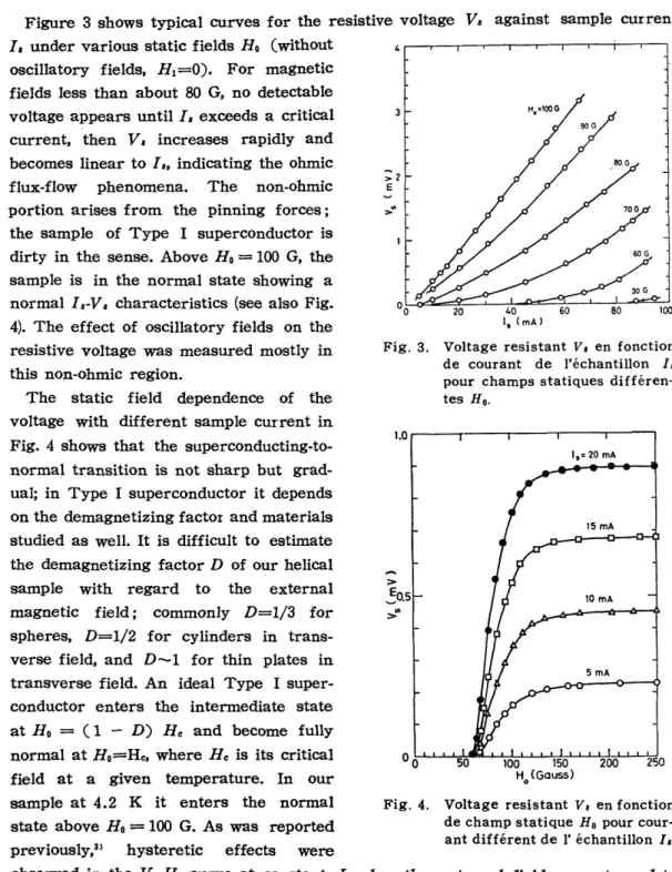
Figure 3 shows typical curves for the resistive voltage V. against sample current I, under various static fields Ho (without
oscillatory fields, H1=0). For magnetic fields less than about 80 G, no detectable voltage appears until I. exceeds a critical current, then V. increases rapidly and becomes linear to la, indicating the ohmic flux-flow phenomena. The non-ohmic portion arises from the pinning forces;
the sample of Type I superconductor is dirty in the sense. Above Ho
=
100 G, thesample is in the normal state showing a normal I ,-V, characteristics (see also Fig.
4). The effect of oscillatory fields on the resistive voltage was measured mostly in this non-ohmic region.
The static field dependence of the voltage with different sample current in Fig. 4 shows that the superconducting-to- normal transition is not sharp but grad- ual; in Type I superconductor it depends on the demagnetizing factor and materials studied as well. It is difficult to estimate the demagnetizing factor D of our helical sample with regard to the external magnetic field; commonly D=1/3 for spheres, D=1/2 for cylinders in trans- verse field, and D-1 for thin plates in transverse field. An ideal Type I super- conductor enters the intermediate state at Ho = (1 - D) He and become fully normal at Ho=He, where He is its critical field at a given temperature. In our sample at 4.2 K it enters the normal state above Ho = 100 G. As was reported previously,3) hysteretic effects were
>
..
Fig. 3. Voltage resistant V. en fonction de courant de l'echantillon I a
pour champs statiques differen- tes Ho.
1.0 r---r"---.---,---,.----.
>
~O.5
>'"
Fig. 4.
Is= 20 rnA
250
Voltage resistant V. en fonction de champ statique Ho pour cour- ant different de l' echantillon I •.
observed in the V,-Ho curve at constant I, when the external field was returned to zero f10m the saturation region.
The resistive voltage enhancement in oscillatory magnetic fields is illustrated in
Figs. 5-7; the data given here were 0.20r---r--r--,----,--,----,--,-.,..---,
obtained with a constant sample current Is=10 rnA close to the critical current.
In Fig. 5 we show the dependence of V 8 0.15
on the ac current I l a t various freq uen- cies of the oscillatory field for different values of Ho, where the abscissa also indicates the field intensity HI proportinal to II (Fig. 2). It can be seen that for low frequency
f <
1 kHz the voltage V 8 increases nonlinearly with increasing ac current II and tends to level off, whereas for high frequenciesf
5 and 10 kHz it rises linearly with II', The nonlinear dependence of VB on /1 (or HI) is demon- strated in Fig. 6 at frequency 100 Hz in a log-log scale; the upper scale gives the corresponding oscillatory field strength.In the vicinity of the critical condition, at which the resistive voltage begins to appear (that is, at Ho=58 G), the voltage VB is seen to increase quadratically with HI and then is likely to approach to
HI-Hl1l2 at higher fields; it is not conclu- sive from the figure which of them is a good expression and we here draw a
Hl1/2 dependence as indicated by a dotted line. As the static field increases, that is, with the increasing density of magnetic flux, the resistive voltage enhancement becomes less dependent on the intensity Hb approaching nearly to the H1-H11!2
line. The effect of the amplitude HI of the oscillatory field on the voltage enhancement can be understood qualita- tively along with the picture predicted by London. 4)
In Fig. 7 is shown the frequency depen-
500Hz
>
E
>"'0.10
~ H.-SSG
oil- .... .o .... H.=S4 G
200 I, (rnA)
Fig. 5. Voltage resistant Vs en fonction de ac courant 11 de l' aimant oscillatoire
a
frequences differ- entes. obtenus a Is=10mA.>
..
Fig. 6.
0.5 1 H, ( G )
2 5 10 20
i i i I I I J i I I I i i 11
15=10 mA, f =100 Hz
58G
Voltage resistant V 8 en fonction de ac courant 11
a
100 Hz pour champs statiques differents Ho.avec /s=10mA. Le haute echelle montre l' intensi te de champ oscilla toi reo
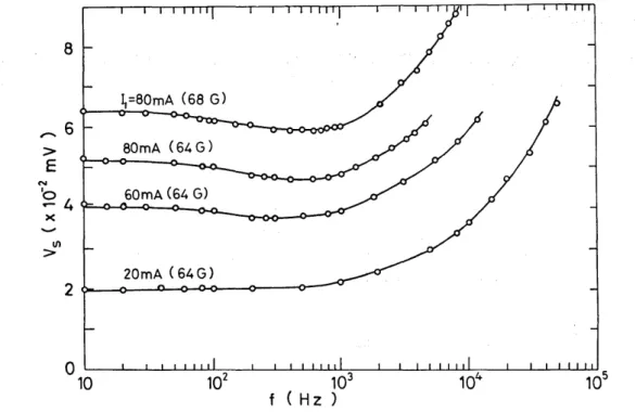
dence of the resistive voltage at various ac currents /1 or HI; the curves were obtained with two different static fields
CHo=
64 and 68 G). It should be noted that the actual intensity- of the oscillatory field varies with the frequency, as shown inFig. 2. However, Fig~ 7 indicates qualitatively the trend of Vs-I characteristics at constant value of HI; in the frequency range 10 Hz--- 1 kHz the voltage is almost
8
,...
6>
E
N
'0
- 4
)(
> II)
2
o
10I,=80mA (68 G)
60mA (64 G)
20mA (64G)
103 f (H z )
Fig 7. Voltage resistant V s en fonction de fn~~quences f de champ magnetique oscillatoire pour intensite different du champ statique, avec 18= lOrnA.
constant, while for higher frequencies it icreases as VB oc fl12.
On the other hand, a detailed study of such a meaSUl ement on Nb foilsIl and Pb films2l by Huebener et ale has shown that (i) the voltage passes through a maximum as a function of
I,
(ii) the frequencyf*
associated with the maximum voltage increases with Ho, and (iii) it is practically independent of the amplitude HI but varies only little with sample current. They have thought that the resistive-voltage enhancement in the presence of an oscillatory magnetic field is caused by the oscillatory eddy currents in the sample and that the variation of this effect with the frequency of the oscillatory field is determined by the relaxation time for the penetration into the specimen of an external magnetic field variation; a simplified treatment is given of the relaxation time 'r for magnetic flux penetration in the case of a thin film geometry with a demagnetizing factor close to one, using an energy-balance argument.Our experimental results do not show any maximum in the V
8-1
curve, which is considered presumably due to our sample geometry (helical form) relative to the external field. It is well recognized that the sample shape is an important factor in the study of magnetic-flux phenomena. We are planning to use a flat sheet of Ta foil instead of helical shape. Nevertheless, the general features presented here of the voltage enhancement can be understood qualitatively in terms of the current256
pictures such as depinning effect, flux-flow resistivity, eddy-current dissipation, and skin effect.
Acknowledgments
We acknowledge T. Shitaya (Matsushita Elec. Ind. Co., Osaka) for supply of the sample used in this work, O. Yamamoto and Y. Tsuyama for the assistance in the measurements.
References
1) R. P. Huebener, G. Kostorz, and V. A. Rowe: J. Low Temp. Phys. 4 (1971) 73.
2) R. P. Huebener, L. G. Stafford, and F. E. Aspen: Phys. Rev. B5 (1972) 3581.
3) M. Inoue, H. Yagi, and T. Tatsukawa : Memoirs Fac. Eng. Fukui Univ. 20 (1972) 139.
4) H. London: Phys. Letters 6 (1963) 162.
Note added in proof.
One of us (M. I.) would like to thank Dr. R. P. Huebener (Argonne National Lab.) for helpful comments on this work.