INVITED SURVEY PAPER
Survey of Cloud-Based Content Sharing Research: Taxonomy of System Models and Case Examples
Shinji SUGAWARA†a),Member
SUMMARY This paper illustrates various content sharing systems that take advantage of cloud’s storage and computational resources as well as their supporting conventional technologies. First, basic technology concepts supporting cloud-based systems from a client-server to cloud computing as well as their relationships and functional linkages are shown. Second, the taxonomy of cloud-based system models from the aspect of multiple clouds’ interoperability is explained. Interoperability can be categorized into provider-centric and client-centric scenarios. Each can be further divided into federated clouds, hybrid clouds, multi-clouds and aggregated service by broker. Third, practical cloud-based systems related to contents sharing are reported and their characteristics are discussed. Finally, future direction of cloud-based content sharing is suggested.
key words: content sharing, client-server, shared storage, peer-to-peer, grid computing, cloud computing, object storage, interoperability, federated cloud, hybrid cloud, multi-cloud, aggregated service by broker, provider centric, client centric
1. Introduction
Due to rapid advances of computers, communication de- vices, and communication networks, diverse and vast amounts of digital contents are exchanged over the Internet, enabling numerous users to enjoy the benefits of technol- ogy. To realize smooth and stress-free content provisioning, searching and retrieving, numerous content sharing systems and supporting technologies have been developed and im- plemented. Currently, cloud computing systems for content sharing, such as exchanging text messages, documents, pho- tos, voice, music, and videos, are important in our daily life, and many interesting systems have been implemented over the Internet.
According to an Internet traffic forecast issued by Cisco [1], global IP traffic in 2015 stands at 72.5 exabytes (EB) per month and will nearly triple by 2020, to reach 194.4 EB per month. On the other hand, the percentage of Con- tent Delivery Network (CDN) traffic in global IP traffic is expected to grow rapidly. CDN traffic in 2015 stands at 23.9 EB per month which is about one third of global IP, will grow to 104.0 EB which is more than half of global IP.
Cloud-based content sharing plays a major role of CDN, and its importance must be getting larger and larger in the next decade.
Manuscript received May 31, 2016.
Manuscript revised September 16, 2016.
Manuscript publicized October 21, 2016.
†The author is with the Department of Information and Com- munication Systems Engineering, Faculty of Engineering, Chiba Institute of Technology, Narashino-shi, 275-0016 Japan.
a) E-mail: [email protected] DOI: 10.1587/transcom.2016EBI0001
However, the concept of cloud computing is rather vague even now, and its definition is partially controversial.
Then, it is sometimes difficult even for the researchers in the computer and communications fields to truly understand the natures of numerous cloud-based content sharing systems working over the Internet. Thus we would like this survey to be some help for the researchers to organize their ideas or concepts on cloud-based content sharing systems.
The rest of this paper is organized into four sections. In Sect. 2, some basic technology concepts supporting cloud- based systems from client-server to cloud computing, includ- ing their relationships and functional linkages, are shown.
Section 3 introduces the taxonomy of cloud-based system models from the aspect of the interoperability of multiple clouds. In Sect. 4, practical cloud-based systems related to content sharing, are introduced, and their characteristics are briefly reported. Finally, summary of this survey is presented in Sect. 5 as well as some discussions on the characteristics of each cloud system models and actual system examples including their relationships. In addition, future directions of cloud-based content sharing are suggested.
2. Basic Concepts and Technologies of Computer Sys- tems Supporting Contents Sharing
This section provides several major conventional models of computer systems supporting content sharing over the Inter- net. Although the models are relatively simple and primitive, each plays a very important role. Especially in the situation where the system architecture is complicated in order to achieve a high efficiency in content sharing, the instances of these models are well served as part of actual cloud-based content sharing systems like the ones illustrated later.
Generally, every system of content sharing over the Internet must incorporate the following three-step process:
(i)publication, which makes the content available, (ii)user discovery, which allows users to discover sources of the content, and (iii)user delivery, which grants users access to the content [2],[3]. It is easy to confirm that many major content sharing systems perform all three of these steps.
We believe that the most common and basic model of all modern computer system architectures is the client-server, and the other major system architectures can be explained as derivatives realized during system extensions, large-scale integrations and/or simplification processes to meet users’
demands. In this section, we deal with the client-server system architecture and its functional derivatives as tech- Copyright©2017 The Institute of Electronics, Information and Communication Engineers
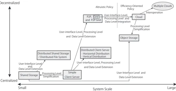
Fig. 1 Relationship among major computer systems concerning system scales and decentralization degrees.
nologies supporting content sharing.
2.1 Client-Server Systems
Because the client-server system is very simple but use- ful, it is one of the most basic and popular computa- tion/communication system models adopted by working sys- tems currently on the Internet. Typical examples used for content sharing systems are a Web server, an FTP server or a DNS server using protocols of HTTP (HTTPS), FTP, and DNS. A Web server and an FTP server are commonly used for thepublicationanduser deliverysteps in many content sharing systems, allowing contents to be preserved and read- ily downloaded anytime. On the other hand, a DNS server is used foruser discoveryto help search for the address of a target server which is assumed to possess the target content.
Generally, a simple client-server system provides cer- tain computational results to its users or client application processes according to their requests. Although there are differing opinions about the definition of this system, many people have advocated that the basic function of the client- server system consists of the following three levels[4]:
• User-interface level
• Processing level
• Data level
Considering these levels, the other major computer system models working over a large-scale network can be explained as derivatives of the above mentioned client-server system.
The relationship among major computer systems is shown in Fig. 1 focusing on their system scales and decentraliza- tion degrees. The existing complicated cloud-based systems mentioned later are combinations of the system models in the figure. For simplicity, we assume that the basic client-server system consists of two parts (i.e., a client and a server),
where the client includes some or all of the user-interface level, while the server assumes the remaining roles.
Thus, we see that a simple client-server system can be extended in all three function levels. In this extension, the system is enlarged to address the deficiency of total perfor- mance by replacing a single server with many processing units or servers. In this case, a centralized client-server sys- tem is changed into a distributed one, which consists of many separated processing units or servers, that are connected via communication links.
Typically this extension occurs in one of two ways:
vertical distributionorhorizontal distribution[4]. The char- acteristic feature of a vertical distribution is that it is achieved by placing logically different components of the system on physically different processing units or servers. For example, it is possible that whole function of a system is divided into three servers and each server is responsible for a different level. It should be noted that how to divide the three levels is flexible, and in principle, the three levels can be divided into as many servers as desired. However, each physically sepa- rated server must be logically different from the others. The system architecture divided inton(n≥2)parts is called the (physically)n-tiered architecture, where as the one that is not divided is called a single-tiered or monolithic architecture.
Meanwhile, in a horizontal distribution, a client or a server may be physically split into logically equivalent parts (i.e., part of a system (e.g., one ofntiers) can be replicated and the replicas share the task of the part’s role). In this case, each replica’s load can be adequate and balanced with others in certain situations. In addition, it is possible to handle rapid growth or even shrink service requests by changing the number of replicas, making the system scalable. This idea leads to the concepts ofPeer-to-Peerand acloud.
The rest of this section introduces six other major com- puter system models as elements of cloud-based content
sharing systems, which are illustrated later, linking exten- sion, large-scale integration, and simplification of the client- server system’s function levels.
2.2 Shared Storage/ Distributed File Systems
A lot of networked and distributed file systems exist asshared storage such as NFS [5], LOCUS [6], AFS [7], [8], and CODA [9]. These systems either use centralized servers (e.g., NFS) or a few distributed replicated file servers (e.g., CODA). Several server-less systems have been designed to achieve higher availability and scalability (e.g.,Farsite[10]
andKosha[11]). Additionally,GFS[12]is a distributed file system designed for data-intensive tasks, but it uses dedicated disks and is specialized for web searches.
Parallel file systems (e.g., GPFS [13], PVFS [14], Frangipani[15], andPetal[16]) target large datasets and are tightly integrated with supercomputers. Distributed logical disks[17] were later built from a decentralized collection of commodity storage appliances by extending ideas from Petal with regard to replication, volume management, and load balancing. Such systems handle replication at the disk segment level but not the dataset level.
Although there are many variations of these systems, they can roughly be divided into simple shared storage sys- tems, which mainly use centralized storage, and distributed storage systems, which distribute their file servers. The for- mer is a simplified model of a simple client-server, reducing the function of the processing level. The latter is an extended model of a shared storage system to increase the functions of the user-interface level and the data level as horizontal dis- tribution similar to an extension from a simple client-server to a distributed client-server to meet users’ or application processes’ requests.
Shared storage and distributed file systems were origi- nally used to supplement main servers while caching, main- taining, and controlling data sets rapidly and extensively. In this sense, thepublication anduser delivery steps are the main roles.
2.3 Peer-to-Peer Systems
Peer-to-Peer(P2P)systemsconsist of distributed nodes and Internet-based applications. Each node is called apeerbe- cause depending on the circumstance, it plays the role of the client or the server, and works in the system on even ground with the other nodes. In this type of system, resources of autonomous participants (e.g., computational power, data storage, network bandwidth, etc.) are connected to provide services (e.g., data/content sharing, distributed computing, user communication/collaboration, etc.) to peers in a de- centralized mode. P2P technologies are typically applied on the Internet’s edge or in ad-hoc networks. P2P systems are often characterized with the following features: Decentral- ization,Scalability,Anonymity,Self-organization, andFault Tolerance.
P2P systems can be roughly classified as either pure
and hybrid. A pure approach lacks a centralized server, and contents shared in the system should be searched by a flooding-based queries transmission (inunstructured P2P), a Distributed Hash Table(DHT) (instructured P2P), etc.
Gnutella [18]andFreenet[19]are good examples of pure P2P systems. In a hybrid approach, the server is referenced first to access meta-information and then communication is carried out between peers. Napster[20]andBitTorrent [21]are examples of hybrid P2P systems. Thesuper-peer approach is an intermediate method. An example of this is KaZaa[22]. In KaZaa, a super-peer owns some information that may not exist in the peers; therefore, if a peer cannot find certain information, it asks super-peers whether they have the information. P2P systems are mainly applied in collaborative content exchanges and file/content management[23].
P2P system is an extension of a simple client-server at the user-interface level, processing level, and data level in common with an extension to a distributed client-server.
The main difference from a distributed client-server is that a peer in the P2P system has some autonomy. P2P provides a very flexible structure, but sometimes may be destabilized.
From the view point of the three necessary processes for content sharing, all are included as system’s functions. For example in the case of pure P2P, content storage is equipped by each peer forpublication, while flooding and peers’ struc- ture according to DHT are available for bothuser discovery anduser delivery.
2.4 Grid Computing
Grid computing is the predecessor of cloud computing al- lowing resource sharing using a dedicated infrastructure to establish a large, distributed computing platform with cross- organizational boundaries[24]–[26]. Grid nodes share ap- plications and resources through a virtualization mechanism across an organization. Grid computing has emerged to help solve large-scale computational problems via high perfor- mance sharing resources.
The architecture of a grid generally consists of five layers: fabric,connectivity,resource,collective, andappli- cationlayers. The fabric layer provides access to various re- sources (e.g., compute, storage, and network resources). The connectivity layer defines core communications and authen- tication protocols for easy and secure network transactions.
The resource layer defines protocols for publication, discov- ery, negotiation, monitoring, accounting, and payment of sharing operations for individual resources. The collective layer monitors and captures interactions across collections of resources and directory services. Finally, the applica- tion layer includes applications of users, on top of the above protocols and API (Application Programming Interface)s.
Grid computing is also an extension of a simple client- server because its user-interface level, processing level, and data level are like an extension to P2P. The fact that the three necessary processes for content sharing are included in the system is also the same as the P2P. These features are common with theP2P gridmentioned below.
2.5 P2P Grid Computing
P2P grid computing[27]combines the features of P2P and grid, with in-and-out flexibility and fast search mechanisms.
The resources of the system are characterized by the col- laborator peers, including clients and/or servers, in a more scalable system than traditional grid computing. P2P grid computing has the same capabilities as traditional grids and autonomous P2P systems. Additionally, it supports numer- ous peers or sites that can be incorporated in the infrastruc- ture of the grid.
In P2P grid, large-scale computational grids are built based on edge-resources (e.g., desktop PCs) with a built-in fault-tolerance. The system offers scalability and improved resource availability compared to grid computing. The full decentralization feature of the P2P grid prevents the nodes from exchanging content and control messages, which main- tains system scalability. In addition, full decentralization prohibits nodes from considering the metadata received by others as trustworthy.
All nodes in the hybrid system are categorized into two types: grid nodes and P2P nodes. The grid nodes are con- nected to help distribute grid resources such as computing cycles, data storage, etc. The grid component of the P2P grid can provide the basic grid services, such as task man- agement, resources scheduling, file operations, and system administration. The P2P nodes are not involved in this grid component.
2.6 Cloud Computing
Cloud computingis a key concept in this paper. The defini- tion of a cloud remains debatable[24],[28]. However, herein we use the following definition: a cloud is large-scale dis- tributed computing driven by economies of scale, in which a pool of abstracted, virtualized, dynamically-scalable, man- aged computational power, storage, platforms, and services are delivered on demand to external customers over the In- ternet[24].
The important points in this definition are:
• Cloud computing is massively scalable.
• Cloud computing can be encapsulated as an abstract en- tity that delivers different levels of services to customers outside the cloud.
• Cloud computing is driven by economies of scale.
• Services can be dynamically configured via virtualiza- tion or other approaches and delivered on demand.
Cloud computing and grid computing are similar con- cepts because the cloud evolved from the grid and relies on the grid as its backbone and for infrastructure support. The essence of this evolution is attributed to a shift in focus from an infrastructure that delivers storage and computational re- sources (grid) to one that is a more abstract resource aimed at economic effects (cloud)[24].
From this viewpoint, cloud computing is the large-scale
integration of a grid computing system’s software and hard- ware at all three function levels. Similar to grid computing, the three necessary processes for content sharing are also available. In addition, cloud computing works economically (i.e., it is designed according to an efficiency-oriented pol- icy), which is a clear difference from P2P and grid computing that are sometimes driven by an altruistic policy.
2.7 Object Storage
Object storageis a large-scale storage architecture in which preserved data are treated as objects that differ from file systems, which manage data as files in a hierarchical struc- ture. Each object consists of the data itself, metadata, and a unique identifier. Data in object storage can be used directly by application processes just like an interface, accessed with the use of the identifier searching in the namespace, and managed by replication and distribution at the object-level granularity.
As a system design policy, numerous physical storages are aggregated and abstracted in object storage systems, and appear to have a huge capacity of storage from users and application processes. This architecture allows this model to provide a relatively inexpensive and scalable service.
Typical examples of object storage are AWS S3 (Sim- ple Storage Service)[29], Microsoft Azure[30], and Google Cloud Storage [31], that are provided by cloud service venders, while examples of open source developments in- clude Swift [32], [33], GlusterFS [34], [35], and Ceph [36],[37].
Object storage is both an extension of shared storage at the user-interface level and data level as well as simplified model of cloud computing at the processing level. Addition- ally, because this system model is used to cache or preserve many kinds of data, including unstructured data and cold data, which is seldom accessed,publicationanduser deliv- erysteps seem to be its main role for content sharing.
3. Taxonomy of Cloud-Based Contents Sharing System Models
This section illustrates typical models of contents sharing architectures using cloud systems, from the viewpoint of cloud interoperability[38].
The most simple system architecture is a single cloud.
However, much more complicated systems are needed for content sharing over the Internet these days, and if we con- sider to implement such a system, using multiple clouds is a reasonable decision, and in this case, cloud interoperability is a very important concept. Cloud interoperability has many merits, including:
• Scalability and high resource availability[39],[40]
• Avoiding vender lock-in[41]
• Geographic distribution and low-latency access[42]
• Cost efficiency and saving energy[41]
Armbrust et al. mentioned that cloud computing refers
Fig. 2 Classification of cloud interoperability scenarios.
to both the applications delivered as services over the Inter- net as well as the hardware and systems software in the data centers that provide such services[41]. In this definition, the data center hardware and software are called a cloud, and their services are generally provided for profit. Apublic cloud is one available to the public in apay-as-you-goman- ner. On the other hand, aprivatecloud is one that belongs to a business or an organization and is not available to the public. A typical cloud environment includes a hundreds of independent, heterogeneous, private, and public clouds[43].
The main stakeholders in cloud computing arecloud users andCloud Providers (CPs). Cloud users are either software/application Service Providers (SPs) who offer a service to consumers or end users who use the cloud services directly. Because SPs offer economical services using the resources provided by CPs, CPs indirectly provide the utility computing services required by a variety of parties. This hierarchy results numerous combinations of CPs and cloud users which include SPs and end users, and gives rise to a number of plausible scenarios between clouds[44].
Because interconnections naturally occur among clouds, clouds must be interoperable. Figure 2 illustrates several scenarios of cloud interoperability. They can be roughly divided into two categories: provider-centricand client-centricinteroperability. If cloud interoperability re- quires CPs to adopt and implement standard interfaces, pro- tocols, formats, and architectural components that facilitate collaboration, it is called provider-centric interoperability.
Provider-centric scenarios are categorized further asfeder- atedandhybrid cloudscenarios. On the other hand, in client- centric interoperability, interoperability is not supported by CPs and cloud customers are required to initiate it by them- selves or via third-party brokers. Client-centric scenarios are also categorized further asmulti-cloudandaggregated service by broker [38]scenarios. The rest of this section illustrates each particular scenario in detail.
3.1 Federated Clouds
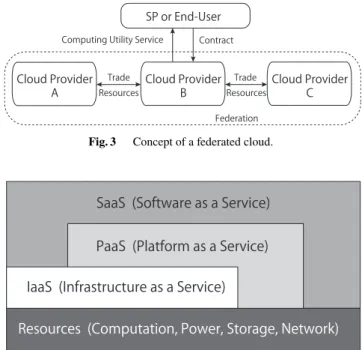
In this kind of system, the SP establishes a contract with a CP, which is a member of a federation. A group of cloud providers are federated and trade their surplus resources among each other to gain economies of scale, efficient use of their assets, and expanded capabilities[43]. The computing utility service is delivered to SPs using resources by one or multiple CPs. The SP may be unaware of the federation
Fig. 3 Concept of a federated cloud.
Fig. 4 Concept of a cloud service stack.
because its contract is with a single cloud provider. The concept of this system is illustrated in Fig. 3.
Cloud services are sometimes categorized into three levels [41]: SaaS(Software as a Service),PaaS (Platform as a Service) andIaaS(Infrastructure as a Service). These service levels form a stacked structure (Fig. 4). This cate- gorization is mainly from the viewpoint of CP’s providing environment to users, and different from the one discussed here, however in provider-centric situation, namely, in an en- vironment where CPs have the initiative to offer the system architecture options to users or SPs, interconnection, i.e., federation in this case, among clouds at different cloud stack layers, may occur.
If an interconnection occur between clouds at, for ex- ample, SaaS and PaaS, this is called adelegationorvertical federation. This type of interconnection is thought to have a rather smooth implementation because role-sharing be- tween the upper layer and the lower layer is clear. On the other hand, if the interconnection occurs between clouds at the same level (e.g., PaaS and PaaS), this is called ahori- zontal federation. This type of interconnection is thought to face many more implementation hurdles.
In a client-centric situation, namely, in an environment where users or SPs have the initiative to form the system architecture by themselves using resources provided by a number of clouds, it is also possible for users or SPs to select and combine clouds at different cloud stack layers for some special effects. This topic will be mentioned in 3.3.
Another concept, which is similar to the cloud federa- tion, is anIntercloud. In many works, these terms are used interchangeably. However they differ slightly. The main difference is that an Intercloud is based on the future stan- dard and open interfaces, while a federation uses a provider version of interfaces. Therefore, federated cloud can be
Fig. 5 Concept of a hybrid cloud.
considered as a prerequisite toward the final goal of the In- tercloud.
3.2 Hybrid Clouds
In the hybrid cloud architecture, an organization that owns a private cloud moves part of its operations to external CPs.
The organization can also sell its idle capacity to other providers during periods of low load. This extension of a private cloud (on-premises) to combine local resources with resources from remote public CPs (third-party) is called hy- brid cloud. The concept of this system is illustrated in Fig. 5.
In this kind of system, SPs or end-user applications can scale out through both private and public clouds when the local infrastructure is insufficient. Furthermore, this system can be extended if the organization offers capacity from its private cloud to others when that capacity exceeds the re- quirements for internal operations. This creates a system that performs economically.
Although hybrid clouds and federated clouds are both categorized in provider centric scenarios and have similar ar- chitectures, there are clear differences. In a federated cloud, multiple clouds, regardless whether each of them is a private or public, try to form a flat structured, high capability entity together to realize an efficient use of resources and to avoid a deficiency of utility provided to users or SPs. Although both have the same goal, a hybrid cloud is a mixture of private and public clouds, and in a common scenario, the organization owning a private cloud enters into a contract with a user or an SP to provide computing utility service, and occasion- ally seeks help from a public cloud that anyone can use its capability.
A hybrid cloud system has typical architectural pat- terns, which are illustrated in[45]. In this article, four typ- ical architectures are introduced:Static placement,Assisted replication,Automigration, andDynamic migration. Addi- tionally, another article discusses the economics of hybrid cloud systems and shows the economic benefits of using a hybrid cloud by comparing it with pure private cloud and pure public cloud[46].
3.3 Multi-Clouds
In this architecture, SPs or end-users are responsible to man- age resources across multiple clouds. Service deployment,
Fig. 6 Concept of a multi-cloud.
Fig. 7 Concept of an aggregated service by broker.
negotiation with CPs, and monitoring CPs during service operations are executed by the SP or end-user applications.
In this case, the SP may require using an adapter layer with different APIs to execute services on various clouds [38].
The important point for employing this architecture is that a separate layer controls everything regarding aggregation and integration of the clouds, and is completely separate from the CPs. Figure 6 illustrates the basic concept of this system.
In the case of aggregating clouds at different stack lay- ers for special effects, the adapter layer must absorb the difference, as mentioned in 3.1.
3.4 Aggregated Service by Broker
If we can assume another stakeholder (i.e., a broker), an- other type of architecture can be designed. Its basic concept is illustrated in Fig. 7. In this type of system, the broker ag- gregates services from multiple CPs and offers an integrated service to the SPs or users. That is, a third-party abstracts the deployment and management of the components. SPs or users benefit greatly from this architecture because the broker provides a single entry point to multiple clouds. In this kind of system, CPs may also be required to install some internal components to support aggregated services by a trusted broker[38].
This system architecture is a one where the adapter layer of multi cloud is picked out from the user’s or SPs’ function entity and becomes another independent entity. Then the part of this system consisting of a broker and clouds looks like a single cloud at highest stack layer of all the clouds from the user or SP’s viewpoint.
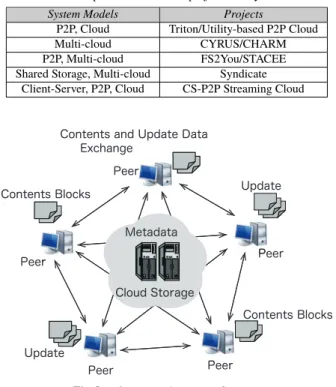
Table 1 Correspondences between projects and system models.
System Models Projects
P2P, Cloud Triton/Utility-based P2P Cloud
Multi-cloud CYRUS/CHARM
P2P, Multi-cloud FS2You/STACEE
Shared Storage, Multi-cloud Syndicate Client-Server, P2P, Cloud CS-P2P Streaming Cloud
Fig. 8 System architecture of triton.
4. Case Studies
In this section, we introduce actual projects of cloud systems.
Examples are selected in terms of potency for contents shar- ing. Because each one is a mixture or hybrid of cloud models and conventional contents sharing architectures, we examine each in detail from the viewpoint of system taxonomy. Ta- ble 1 depicts the correspondence between the projects and basic or cloud-based system models.
4.1 Triton
Triton[47]is a peer assisted single cloud storage system with a hybrid architecture of P2P and a cloud. Numerous users who have some contents to share with others are intercon- nected by a P2P network and collaborate on data in the cloud resources. Thus, they exchange split blocks of a shared con- tent item with each other without serious congestion due to the benefit of a P2P network. Fig. 8 illustrates the system architecture of Triton.
As for contents update, instead of waiting until all the updates are propagated in the cloud’s internal servers, and thus risking to access to stale content item, users (i.e. peers) in this system start to push the updated content items between themselves by exploiting direct communication channels. To maintain consistency of updated shared contents, operations in Triton are based on a state machine replication protocol.
The state machine approach[48],[49]is a general method for implementing a fault-tolerant service by replicating servers and coordinating clients’ interactions with server replicas.
A cloud is used as a coordination rendezvous, which
stores only the meta information about the shared contents, such as a list of peers and a Merkle Tree (i.e., hash tree) calculated by the content file blocks to track the file updates.
A peer who wants to obtain a file retrieves the information about the hash tree that composes the blocks and a list of the peers who have the blocks of the desired content item.
4.2 P2P Cloud Hybrid for Utility-Based Contents Sharing (Utility-Based P2P Cloud)
One of the services that a cloud provides is online storage, which is classified as IaaS. One good example is Amazon S3 (Simple Storage Service) [75]. Online storage can be used through the Internet and there is virtually no capacity limitation as long as the user pays. Tomimori et al. proposed a content sharing method according to contents utility func- tion in hybrid P2P network under the environment where storages of both peers and cloud system are available[76].
Content replication is executed similar to the ERCT- based method[77], and the system calculates the utility value of each content item shared in the system network according to the contents’ reference frequency and capacity.
Each content item is relocated within a certain period from a peer’s storage to cloud’s storage or vice versa, ac- cording to the utility value.
Difference between Triton and Utility-based P2P Cloud These systems are similar from the view point of the system configurations, each of which includes both P2P and cloud, and therefore, they are categorized together in the same class in Table 1. However, the design concept and intended purpose are completely different.
4.3 CYRUS
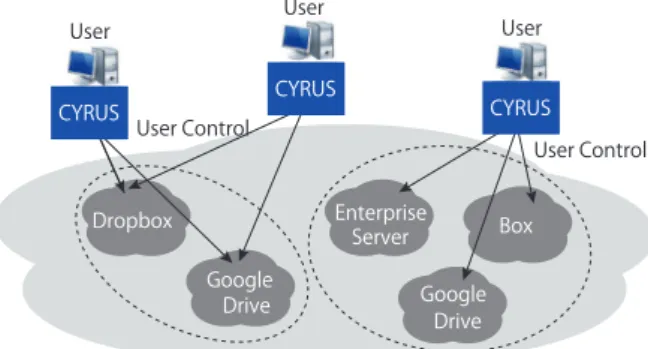
CYRUS[51]is a distributed, client defined architecture that integrates multiple autonomous Cloud Storage Providers (CSPs) into one unified cloud, allowing individual users to specify their desired performance levels and share files or contents. CYRUS ensures user privacy and reliability by scattering files into smaller pieces across multiple CSPs, so that no CSP can read user’s data. In addition, CSPs adopted in this system are selected by an algorithm to minimize the latency for downloading the shared contents or data. To accommodate multiple autonomous users’ preference, the system allows the users to upload their updated contents or files simultaneously, and detects conflicts, if any, after the fact from the client.
CYRUS does not treat CSPs as peers nor does it as- sume that users directly communicate with each other. In- stead each CSP, which is treated as a single node, becomes an autonomous storage resource separately controlled by the user (Fig. 9). This distributed user-controlled architecture enforces privacy and reliability by dividing the user’s con- tents or files into small pieces and redundantly scattering these pieces to multiple CSPs. Thus, attackers must obtain
Fig. 9 System architecture of CYRUS.
data from multiple CSPs to steal a file or a content item. On the other hand, the files are easily recovered if some of CSPs fail. File pieces can be uploaded and downloaded in parallel to reduce latency. Because the user controls the file distri- bution, users can choose how many CSPs to adopt, where to distribute the file pieces so as to define customized privacy, reliability, and latency.
CYRUS has three main functions:
• Integrating multiple clouds
As explained above, CYRUS scatters file pieces to mul- tiple CSPs so that no single CSP can reconstruct a user’s data. The file pieces are stored more than necessary in redundant manner for easy file recovery. This idea is from the(t,n) secret sharing scheme [52], which di- vides user data intonshares, where each share is stored on a different CSP. Secret Sharing divides and encodes the data in such a way that reconstructing any part of the original data requires at leastt of the file shares.
Takingt<nensures reliability, and otherwise, ensures that multiple CSPs are required to recover user data.
Users can reconstruct the file using the shares from any tCSPs.
• Scaling multiple users
To download files, users must know the locations of the file’s shares. Thus, a separate metadata file for each file stored on the cloud should be maintained;
when a user uploads a file, it records the share locations in this metadata. The metadata is stored in a logical tree at CSPs and users are simultaneously maintaining local copies of the metadata tree for efficiency. Each user can synchronize the local copies to track updated share and file locations. The tree structure also allows CYRUS to handle conflicting file updates. Users do not lock a file while while modifying it. Instead users can upload conflicting file versions as different nodes on the metadata tree. The tree is then traversed to find and resolve file conflicts.
• Optimizing cost and performance
CYRUS reduces users’ cost by limiting the amount of data stored on CSPs. Before scattering a file, it is divided into smaller discrete chunks. Unique chunks are then divided into shares using secret sharing. The
Fig. 10 Mapping shares to CSPs.
shares are finally scattered to the CSPs (Fig. 10). Since different files can use the same chunks, deduplication reduces the total amount of data stored in CSPs, con- serving storage capacity. Users can choose the number of shares to upload in order to satisfy reliability and privacy constraints (i.e., n and t for secret sharing).
Adjusting these parameters allows CYRUS to adapt to changes in cloud conditions and user preferences. After choosingn, users select the CSPs so that they do not share a cloud platform, and this minimizes the latency of shares’ downloading.
CYRUS is not the first to recognize the merit of the
“cloud of clouds” approach. DepSky[53]also controls mul- tiple CSPs from the user, but it does not necessarily address practical problems in large-scale deployment.
Other similar works integrate multiple CSPs using proxy servers [54]–[58]. The proxy can scatter and gather user data to and from multiple CSPs, providing transparent access for users. Although the proxy server is a data sharing point among multiple clients, allowing greater deduplication efficiency, it is also a SPOF (single point of failure).
Cloud integration from users has been proposed in [53], [59]–[62]. However, CYRUS provides a customiz- able framework that sets reliability and privacy levels while optimizing users’ admissible delays in accessing and storing files.
4.4 CHARM
CHARM [65] is a system with a multi-cloud data-hosting scheme, which selects several suitable clouds and an appro- priate redundancy strategy to store data while minimizing monetary costs and maximizing guaranteed availability. The system also has a transition process to redistribute data ac- cording to the variations of data access patterns and pricing clouds.
Existing cloud services exhibit great heterogeneities in terms of both working performance and pricing policies be- cause they build their respective infrastructure and continu- ally upgrade it with newly emerging gears. They also design different architectures and apply various techniques to make their services competitive. Such system diversity can be observed across cloud vendors[66].
Due to numerous cloud vendors and their heterogeneous
Fig. 11 Concept of CHARM using multi-cloud compared with single cloud implementation.
performances or policies, customers must decide which cloud(s) are suitable for storing their contents or data and which hosting strategy is the most economical. If a customer places his/her data into a single cloud and simply trusts to luck, the so-called“vendor lock-in risk” may occur. The vendor lock-in risk arises in the situation such as data migra- tion to another cloud vendor due to price adjustments of the employed cloud vendor, unexpected bankruptcy of the cloud vendor, uncontrollable data unavailability, etc. Therefore, multi-cloud data-hosting, which distributes data across mul- tiple clouds to enhance redundancy and reduce the vendor lock-in risk, has received wide attention recently.
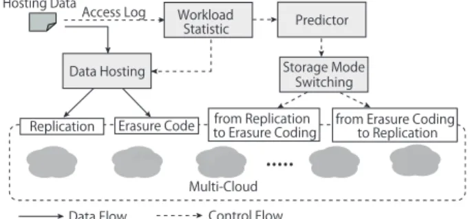
The concept of a multi-cloud in CHARM is illustrated in Fig. 11. The “proxy” component plays a key role by redi- recting requests from client applications and coordinating data distribution among multiple clouds. Figure 12 depicts the proxy part in detail. There are main four components in CHARM:Data Hosting,Storage Mode Switching (SMS), Workload Statistic, andPredictor. Their functions are ex- plained briefly below.
• Workload Statistic collects and tackles access logs to guide the placement of data, and sends statistic infor- mation to Predictor, which guides the action of SMS.
• Data Hosting stores data using replication orerasure coding[67]according to the size and access frequency of the data. To provide high availability and reliability while introducing low storage overhead,erasure cod- ing, which is based on the “Reed-Solomon code”, has been widely applied to storage systems.
• Storage Mode Switching (SMS) decides whether the storage mode for certain data should be changed from replication to erasure coding or vice versa according to the output of Predictor.
• Predictor predicts the future access frequency of files. Numerous quality prediction algorithms ex- ist. CHARM adopts the weighted moving average ap- proach.
The prevalence of multi clouds can be explained in three folds. First, a few researches have examined multi-cloud sys- tems. DepSky[53]guarantees data availability and security based on multiple clouds, allowing critical data (e.g., medical and financial data) to be securely stored. RACS[54]deploys erasure coding among different clouds in order to reduce the
Fig. 12 System architecture of CHARM (proxy part).
vender lock-in risk and monetary costs. Second, new types of cloud vendors (e.g.,DuraCloud[68]andCloud Foundly [69]) have emerged and rapidly grown to provide real ser- vices based on multiple clouds. Third, new development tools like Apachelib cloud [70]provide a unified interface above different clouds, which facilitates migrating services among clouds.
However, critical problems remain: (i) how to choose appropriate clouds to minimize monetary costs in the pres- ence of heterogeneous pricing policies, and (ii) how to meet the specific availability requirements of different services.
CHARM tries to address these two problems.
Difference between CYRUS and CHARM
Although CYRUS and CHARM are both categorized into Multi-cloud system, the former is mainly designed for minimizing the latency in accessing and storing files as well as providing customizable reliability and privacy levels to the users, whereas the latter seems mainly to try to minimize monetary costs.
4.5 FS2You
FS2You[63]is a peer-assisted semi-persistent online storage system. Generally, P2P file sharing systems do not provide guarantees on shared file availability, while server-based on- line storage system can make such guarantees at the pro- hibitive cost of server bandwidth and storage. The design objective of FS2You is to achieve a reasonable and balanced tradeoff between these extreme system models. Although there is no clear description, the servers forming FS2You (i.e., “online storage” stated in [63]) seem to be a cloud system or something similar.
Figure 13 illustrates the hybrid system architecture of FS2You. This system consists of four main components:
Directory Server,Tracking Server,Replication Server, and Peers.
• Directory Server
A directory server keeps the information of all the files or contents shared in this system, including the file IDs and the hash values (each file ID is linked with the hash value of the corresponding file).
• Tracking Server
Fig. 13 System architecture of FS2You.
This server maintains the participating peers’ informa- tion for each file.
• Replication Server
This server keeps contents shared in this system accord- ing to the system’s server strategy.
• Peers
There are two types of peers in the system: (i) those that upload files to servers (i.e.,uploading peers) and (ii) those that download files (i.e.,downloading peers).
In Fig. 13, arrows (1), (2), and (3) represent the interac- tion between a peer and servers for uploading new content.
Arrows (4), (5), and (6) represent the interaction between peers and tracking server to maintain the overlay. Arrow (7) represents the gossip communication and file block sharing among peers. Arrows (8) and (9) represent a peer requesting help from a replication server when it is difficult for the peer to find or retrieve the necessary file from the other peers.
To upload a file, a peer computes the hash value of the file and issues a request(s) to the directory server. The directory server determines whether the file is new, and then it redirects the file to one of the replication servers. Relevant information is updated in the tracking server and the URL for this file is generated for other peers to retrieve the file.
Each file is divided into fixed size blocks of 256 KB.
ABlock Map(BM) is introduced to specify the availability of blocks at each peer[64]. The periodic exchange of BMs among peers enables them to locate the required blocks.
Each peer can retrieve distinct blocks from active partners simultaneously.
One interesting point of this system’s file replication strategy is that the system allows peers to be more actively involved in exchanging popular file than the servers, and it tries to allocate more server resources to unpopular files stored in fewer peers. Generally, each fileiin this system is assigned a reference index Hi, which monitors the ratio between uploaded file sizes and file access frequencies. The reference indexHiis calculated per day asHi=Si/Fiwhere Si is the size of fileiandFi is its daily access frequency. In FS2You, ifHi is low, the file is either small or popular, and such files remain persistent in the servers. Files with higher Hi are removed from the servers. To avoid excessive use
Fig. 14 System architecture of STACEE.
of server storage, large sized files can be stored only if they have substantial user interests and popularity. This policy is similar to the system described in 4.2.
4.6 STACEE
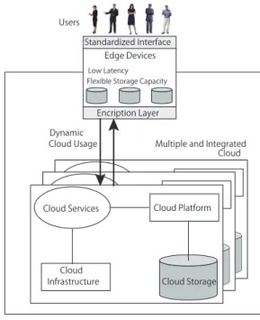
STACEE[71]is a storage cloud system using edge devices provisioning their resources in P2P manner, thus this system is categorized as both multi-cloud and P2P cloud simulta- neously. The term “edge device” originates from telecom- munications and refers to routers, routing switches, or multi- plexers. However, in this system, it mainly means the devices that are much closer to end users (e.g., mobile phones, PCs, set-top-boxes, networked storage devices, etc.). Combining all end-user edge devices may result in a scalable, very flexi- ble storage capability that keeps data comparatively close to the user, increasing availability, while reducing latency. This system aims at Quality of Service (QoS)-aware scheduling in a P2P storage cloud. It is built with edge devices by de- signing an optimization scheme that minimizes energy from a system perspective while simultaneously maximizing user satisfaction from the individual user perspective. Figure 14 illustrates the system architecture.
In this system, multiple clouds exist, and each one incor- porates edge devices for data storage. Edge devices access the services being offered within the cloud through an en- cryption layer. An edge device’s moving from a cloud to another inside its boundary, allows dynamic cloud usage, which can be realized on the edge devices themselves. This also facilitates the integration of multiple clouds enabling applications to not only run on a single cloud but on multiple ones.
As shown in Fig. 14, each cloud consists of the follow- ing main components:
• Cloud Storage
This includes physical or virtualized storage.
• Cloud Platform
This component facilitates the deployment of applica- tions in such way that costs and complexity of man- agement the underlying hardware and software is re- duced (i.e., application framework such as Ruby-on- Rails, .Net Framework, Python Django, etc.).
• Cloud Services
This part comprehends the services needed to deliver cloud storage over the Internet in real time (e.g., queuing services).
• Cloud Infrastructure
This facilitates infrastructure as a service (IaaS) by delivering virtualized platforms (e.g., Eucalyptus, Hadoop, Nimbus[72], etc.).
This cloud network can be dynamically expanded by the ad-hoc addition of further edge devices. Various search strategies can be used to locate data (a number of approaches exist within the P2P research literature to support data dis- covery and query routing). A structured network topology enables a quicker discovery than flooding-based approaches, which may result in a longer discovery time and latency.
Because edge devices may join and leave an ad-hoc network (i.e., P2P network integrated with the multi-cloud), it is necessary to determine which request is processed on which edge device. The level of commitment of the edge devices (i.e., guaranteed uptime of the devices) may vary, and therefore, has an impact on any discovery strategy being supported.
A P2P cloud implementation also has many limitations.
(i) The system may be unstable if a high churn rate of peers (i.e., peers join in or drop off from the network at a high frequency) is likely. (ii) The stability of edge devices may have significant variability (i.e., some devices may be very stable, while others are very unstable). (iii) Device properties may also vary significantly (e.g., energy demands of devices, storage capacity, etc.). This system tries to overcome these limitations.
Difference between FS2You and STACEE
FS2You and STACEE are both categorized into the same sort of the systems with P2P and Multi-cloud, and their system configurations and usages are also similar. However, the former is mainly designed for the progress of shared file availability with reasonable cost, whereas the latter is designed for the improvement of QoS for content retrieval.
FS2You uses multiple clouds, to be sure, bu each cloud plays a specific role of its own, and seems to be vertical role- sharing, whereas the STACEE consists of some independent cloud components standing in parallel.
4.7 Syndicate
Syndicate[50]is a wide-area storage system that abstracts a
Fig. 15 Application architecture with and without a syndicate.
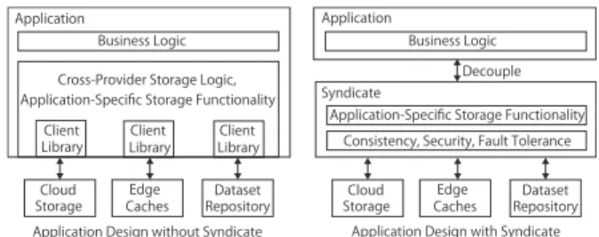
coherent storage from already deployed commodity compo- nents such as cloud storage, edge caches, and other dataset providers. The uniqueness of this system is that it not only offers consistent semantics across multiple providers of datasets, but also supplies a flexible programming model to applications, so they can define their own provider-agnostic storage functionality. This means that Syndicate decou- ples applications from providers, and allows appellations to choose the providers based on how well they enhance the data or the contents’ locality and durability, instead of whether they provide the necessary features.
In general, contents or data providers offer two kinds of utility benefits: data durability and access locality. Cloud storage and dataset providers improve durability by repli- cating contents or data to geographically distributed data centers, while edge caching providers improve locality by placing temporary replicas of contents or data at sites closer to users who consume them than the original contents servers (i.e., lowering contents retrieval latency and increasing band- width).
Utility benefits can be aggregated. Generally, multiple providers yield more utility than a single one, and improve- ments to one provider enhance the system’s overall utility.
However, making such improvements is non-trivial because each provider has a different API with unique functional semantics in the application design of the conventional dis- tributed contents or data sharing systems. The system devel- opers must design the application with coupling its storage logic to provider implementations (Fig. 15 left).
The main idea of Syndicate is to avoid this coupling and to be wide-area software-defined storage service that runs on top of the unmodified contents or data providers (Fig. 15 right). It provides an extensible interface for implementing domain-specific storage functionality in a provider-agnostic way, while automatically addressing common cross-provider consistency, security, and fault-tolerance requirements. Us- ing Syndicate lets system developers create a storage service for their applications with an aggregated utility of multi- ple underlying providers without having to build and deploy a whole storage service from the ground up. Therefore, Syndicate offers virtual cloud storage through provider com- position (Fig. 16).
Syndicate must distinguish among the application’s data records in order to apply domain-specific storage function- ality. Additionally, it must allow the application to structure and search its data records efficiently in a way that is not cou-
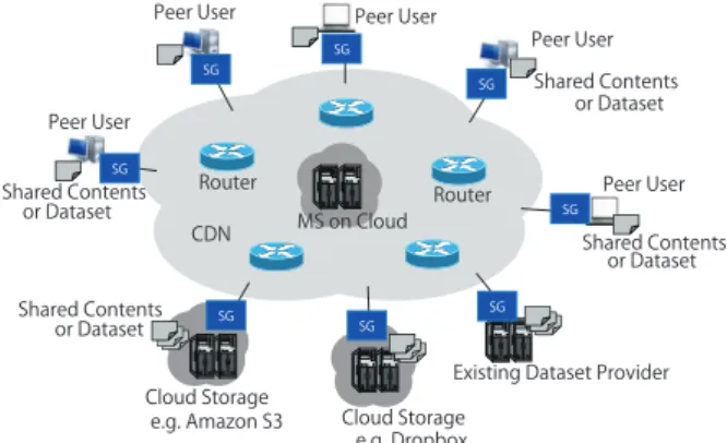
Fig. 16 System architecture of syndicate.
pled with the underlying provider’s semantics. To achieve this, Syndicate defines three kinds of data abstractions: ob- jects,directories, andVolumes.
Objects store record data or contents, as well as meta- data to control the storage functionality. They are organized hierarchically by directories, which realizes efficient organi- zation and searchability by application. A Volume binds a rooted tree of directories to a set of providers and a set of principals (a Volume’s owner etc.). Within a Volume, object data can be distributed across one or more providers, and accessed by one or more principals.
To provide these abstractions to applications, Syndicate providesSyndicate Gateways(SGs) andMetadata Services (MSs). SGs have three variants based on how it interfaces with external providers:
• User SG
Interfaces with edge caches for an application endpoint
• Replica SG
Interfaces with cloud storage providers
• Acquisition SG
Interfaces with dataset providers
MSs help SGs coordinate globally. They maintain the authoritative state of each Volume’s metadata. Additionally, they help the system scale, tolerate faults, and maintain con- sistent data. A MS binds each SG to one Volume, and helps SGs discover their peer SGs.
In a typical deployment, an application uses one MS, and places data in objects distributed across one or more Volumes. Application endpoints run User SGs locally to access Volume data, and the developer provisions other SGs to attach cloud storage and external datasets.
4.8 CS-P2P Streaming Cloud
Trajkovska et al. proposed a multimedia streaming cloud using a hybrid structure of a client-server (CS) and a P2P network[73]. In this system, servers on clouds are connected to clients and working as a CS system. Simultaneously peers are connected to the clients as a P2P network. All work together as one system in both a centralized and a distributed
Fig. 17 System architecture of CS-P2P streaming cloud.
manner. To take advantage of the cloud paradigm and make multimedia streaming more efficient, APIs are introduced in the cloud. The APIs contain a built-in function for automatic QoS calculations, allowing the QoS parameters such as band width, jitter, and latency, to be negotiated among a cloud service provider and its potential clients.
Before this research, Fouquet et al. proposed a P2P- based distributed application-layer multicast scheme for a video streaming tree[74]. In this scheme, a distribution tree topology is formed in the network, and some nodes play the roles of relay servers and controlling peers. They also discussed its integration with the cloud (i.e., they suggested that the important nodes should be replaced with clouds to stabilize the system). However, latency and the bandwidth issue were not sufficiently discussed.
Trajkovska et al., seemed to be inspired by the Fou- quet’s research, and think that the cloud paradigm is the key for bringing back the CS topology in multimedia communi- cations. Expanding the cloud paradigm for P2P streaming support could benefit both cloud service providers and end users.
Figure 17 illustrates a general view of of the proposed architecture containing multimedia streaming servers. This system contains some streaming service levels. The First level clientsare directly connected to the server. Similarly, higher level clients are defined. When a first class client logs in, it consults a Web server with API and chooses one among the three types of price packets (e.g., Gold, Silver andBronze). Then, it initiates a contract directly with the provider of the service for desired streaming quality.
Similarly, higher level clients consult the API functions and obtain an information list with the QoS status for all connected clients and then determine which client to con- nect. By doing this, they agree on a lower streaming quality (determined according to the price model for higher level customers) and make a contract with a first or higher level customer instead of the provider. In addition, it is possible for peers to connect to higher level clients who offer their ser- vice for free. In this way, the streaming topology is organized in a tree based manner.
The service provider has direct centralized management for the contract politics among all types of customers. It also controls the streaming and the stored content on the server with the possibility of creating a contract with an external server for single or short-term streaming. This may cause growth in the viewing demands.
Such cooperation with the service provider acting as a mediator among third party servers and its own clients contributes to business as more streaming contents become available. The owner of an external streaming server profits from the cooperation with a cloud service provider. Addi- tionally, this system offers a stable service that relies on a scalable cloud computing platform offering a higher band- width, lower latency, better load balancing, scalability, and robustness.
5. Overview, Discussion and Future Directions
This paper illustrates various content sharing systems that take advantage of cloud storage and cloud computing tech- nologies as well as related conventional basic concepts and technologies supporting content sharing.
First, we highlight some basic concepts of modern com- puter systems in Sect. 2. We tracked the functional link- ages among them from a client-server through shared stor- age/distributed file system, P2P, grid computing, and P2P grid to reach cloud computing and object storage. In addi- tion, their relationships are discussed. If the client-server system is the standard, then the other systems can be consid- ered as derivatives. Although this notion is not necessarily correct in terms of the development history or evolution pro- cess, we show a perspective of the relationships and func- tional linkages among major concepts in modern computer systems. Each of which is an important concept to reach the height of today’s various cloud-based content sharing systems.
Second, based on the above mentioned basic technolo- gies, we illustrate the taxonomy of cloud systems, which are especially useful for contents sharing in terms of cloud in- teroperability. We discuss federated clouds, hybrid clouds, multi-clouds, and aggregated service by broker in Sect. 3.
The former two models are categorized into provider-centric, while latter two are considered client-centric scenarios. Mo- tivations for interoperability can be easily presented such as scalability, vendor lock-in avoidance, low latency, cost efficiency, etc.
If a cloud-based system needs to enlarge its scale of service, a scale-out strategy rather than scale-up is used in general regardless of its system model as well as type of cloud interoperability, because cloud is better suited for horizontal distribution for the case of its function enhancement, and can scale out efficiently with improving cost-performance ratio. One of the cloud system’s major horizontal scale-out approaches is interoperation of multiple clouds.
Generally in the interoperation of multiple clouds, the system can avoid the problem ofidle capacity(where the cloud’s resources are not fully utilized all the time) and
the problem ofpeaks in demand(where the cloud is over- loaded for a certain period) by sharing the resources with other clouds, which also reduces the system’s total operation costs. In the provider-centric scenario, operations running in a cloud can be migrated to another cloud. This is a clear accommodation method, and achieves maximum system ca- pability with minimum resources.
In principle, operation migration may be available in any cloud system model. However, it seems to be difficult to migrate processes from one cloud to another in client- centric scenarios because each cloud is clearly separated and the processes should migrate through SP, user, or broker’s area. Even if different communication channels among the clouds can be used, the SP or broker should give all the directions for the migration. In the model of hybrid cloud mentioned in 3.2, which is categorized as a provider-centric scenario, a private cloud with the initiative of a service can realize a migration operation positively.
When the multiple clouds interoperation is expanded geographically, it can use the electricity of the cheapest price by taking advantage of time-zone differences. Additionally, if the cloud’s datacenter can be allocated in a cold weather region, the cooling power can be reduced. Then the sys- tem expansion due to the cloud interoperation can reduce costs regardless of the system model. Similarly, this kind of geographical expansion is also useful for a low latency of service. If data centers scattered around the world, it is not difficult for the CP to satisfy the QoS (Quality of Service) of geographically dispersed service customers.
The problem of vender lock-in is serious for cloud users.
This problem is recognized from the users or the SPs’ side.
It is difficult for either to resolve it independently, especially in systems categorized as provider-centric scenario, because cloud services are provided under the initiative of CPs, which tend to take priority of the “terms of use” in the scenario. A multiple cloud system of client-centric scenarios, in which a customer (i.e., an SP or a user) can individually utilizes each cloud depending on the situation similar to CHARM (mentioned in 4.4), must be adopted to avoid the vendor lock-in problem.
Third, we introduce some practical cloud-based sys- tems, which can be used for contents sharing such as Triton, Syndicate, CYRUS, FS2You, CHARM, STACEE, CS-P2P Streaming Cloud and P2P-Cloud Hybrid for Utility Based Contents Sharing. Each can be classified into one, or several of the above-mentioned categories of system models. All these systems can be complicated, but they have interesting functions.
According to Celesti et al., the evolution of cloud com- puting can be hypothesized in three sequential phases:mono- lithic,vertical supply chain, andhorizontal federation[43].
In the monolithic stage, cloud providers are based on their proprietary architectures that create islands of cloud. In the vertical supply chain stage, some cloud providers leverage services from other provider, e.g., a SaaS provider deploys services of an IaaS provider as its own to serve its customers.
In horizontal federation, different sized cloud providers fed-
erate themselves to gain benefits of a cloud federation, e.g., a fully utilized IaaS provider may use resources in an underuti- lized provider to accommodate more VM (Virtual Machine) requests.
Most of the cloud-based systems picked up in this sur- vey have the architecture of multi-cloud. Although multi- cloud system seems to be included in the horizontal federa- tion in the general meaning, if the hypothesis noted above is true, cutting-edge cloud based content sharing systems have already reached the final stage that Celesti et al. mentioned.
As a future direction, it is important that cloud-based content sharing is fused with systems or technologies based on the content- (or information-) centric paradigm[78]as well as with systems based on the conventional end-to-end (i.e., host-centric) paradigm. There are numerous expec- tations for the advancement of cloud computing in many fields, however from the viewpoint of content sharing, it must be valuable for the clouds to keep on playing a major role to provide users the above mentioned three-step process:
publication,user discovery, anduser deliveryin any circum- stances. If clouds cache huge and unpopular content items, which are not suitable for caching in the network, content exchange over the Internet may be more affluent and rich, taking advantage of content-centric paradigm. We believe a great potential of cloud-based content sharing systems which continue to provide significant benefits to the network users even in the future.
References
[1] White paper: Cisco VNI Forecast and Methodology, 2015–2020, http://www.cisco.com/c/en/us/solutions/collateral/service-provider/
visual-networking-index-vni/complete-white-paper-c11-481360.html, [Online].
[2] G. Tyson, A. Mauthe, S. Kaune, P. Grace, A. Taweel, and T. Plagemann, “Juno: A middleware platform for supporting delvery- centric applications,” ACM Trans. Internet Technol., vol.12, no.2, pp.1–28, Dec. 2012.
[3] H. Rajaei and N. Hakami, “P2P grid technology for virtual class- rooms and laboratories,” Proc. 16th Communications and Network- ing Symposium (CNS’13), article no.11, April 2013.
[4] A.S. Tanenbaum and M.V. Steen, Distributed Systems, Pearson Ed- ucation, 2007.
[5] B. Nowicki, “NFS: Network file system protocol specification,” Net- working Working Group, RFC1094, 1989.
[6] G. Popek and B.J. Walker, The LOCUS Distributed System Archi- tecture, MIT Press, 1985.
[7] J.H. Howard, “An overview of the andrew file system,” Proc. Winter 1988 USENIX Conference, pp.23–26, 1988.
[8] J.H. Morris, M. Satyanarayanan, M.H. Conner, J.H. Howard, D.S.
Rosenthal, and F.D. Smith, “Andrew: A distributed personal comput- ing environment,” Commun. ACM, vol.29, no.3, pp.184–201, March 1986.
[9] M. Satyanarayanan, J.J. Kistler, P. Kumar, M.E. Okasaki, E.H. Siegel, and D.C. Steere, “Andrew: A distributed personal computing envi- ronment,” IEEE Trans. Comput., vol.39, no.4, pp.447–459, April 1990.
[10] A. Adya, W.J. Bolosky, M. Castro, R. Chaiken, G. Cermak, J.R.
Douceur, J. Howell, J.R. Lorch, M. Theimer, and R.P. Wattenhofer,
“FARSITE: Federated, available, and reliable storage for an incom- pletely trusted environment,” Proc. 5th Symposium on Operating Systems Design and Implementation (OSDI), pp.1–14, USENIX,
Dec. 2002.
[11] A.R. Butt, T.A. Johnson, Y. Zheng, and Y.C. Hu, “Kosha: A peer- to-peer enhancement for the network file system,” Proc. ACM/IEEE Conference on Supercomputing, ACM/IEEE, Nov. 2004.
[12] S. Ghemawat, H. Gobioff, and S.T. Leung, “The google file system,”
Proc. Nineteenth ACM Symposium on Operating Systems Principles (SOSP’03), pp.29–43, ACM, 2003.
[13] F. Schmuck and R. Haskin, “GPFS: A shared-disk file system for large computing clusters,” Proc. 1st USENIX Conference on File and Storage Technologies (FAST’02), article no.19, 2002.
[14] P.H. Carns, W.B.L. III, R.B. Ross, and R. Thakur, “PVFS: A parallel file system for linux clusters,” Proc. 4th Annual Linux Showcase and Conference, USENIX Association, Oct. 2000.
[15] C.A. Thekkath, T. Mann, and E.K. Lee, “Frangipani: A scalable dis- tributed file system,” Proc. Sixteenth ACM Symposium on Operating Systems Principles (SOSP ’97), pp.224–237, ACM, 1997.
[16] E.K. Lee and C.A. Thekkath, “Petal: Distributed virtual disks,” Proc.
7th International Conference on Architectural Support for Program- ming Languages and Operating Systems, pp.84–92, ACM, 1996.
[17] S. Frølund, A. Merchant, Y. Saito, S. Spence, and A. Veitch, “Fab:
Enterprise storage systems on a shoestring,” Proc. 9th Conference on Hot Topics in Operating Systems (HOTOS’03), vol.9, pp.169–174, 2003.
[18] M. Portmann, P. Sookavatana, S. Ardon, and A. Seneviratne, “The cost of peer discovery and searching in the gnutella peer-to-peer file sharing protocol,” Proc. 9th International Conference on Networks, pp.263–268, IEEE, Oct. 2001.
[19] I. Clarke, O. Sandberg, B. Wiley, and T.W. Hong, “Freenet: A distributed anonymous information storage and retrieval system,”
International Workshop on Designing Privacy Enhancing Technolo- gies: Design Issues in Anonymity and Unobservability, pp.46–66, Springer-Verlag New York, 2001.
[20] P. Golle, K. Leyton-Brown, and I. Mironov, “Incentives for sharing in peer-to-peer networks,” Proc. 3rd ACM Conference on Electronic Commerce (EC’01), pp.264–267, ACM, 2001.
[21] B. Cohen, “Incentives build robustness in bittorrent,” Proc. 1st Work- shop on Economics of Peer-to-Peer Systems, Berkeley, CA, USA, June 2003.
[22] J. Liang, R. Kumar, and K.W. Ross, “The kazaa overlay: A measure- ment study,” Computer Networks, vol.50, no.6, pp.842–858, 2005.
[23] D.S. Milojicic, V. Kalogeraki, R. Lukose, K. Nagaraja, J. Pruyne, B. Richard, S. Rollins, and Z. Xu, Peer-to-peer computing, Hewlett- Packard Company, 2002.
[24] I. Foster, Y. Zhao, I. Raicu, and S. Lu, “Cloud computing and grid computing 360-degree compared,” Proc. Grid Computing Environ- ments Workshop, IEEE, pp.1–10, Nov. 2008.
[25] I. Foster and C. Kesselman, The Grid 2: Blueprint for a New Com- puting Infrastructure, Morgan Kaufmann Publishers, 2003.
[26] B. Jacob, M. Brown, K. Fukui, and N. Trivedi, Introduction to Grid Computing, IBM International Technical Support Organiza- tion, 2005.
[27] N. Andrade, F. Brasileiro, W. Cirne, and M. Mowbray, “Automatic grid assembly by promoting collaboration in peer-to-peer grids,” J.
Parallel Distr. Com., vol.67, no.8, pp.957–966, Aug. 2007.
[28] J. Geelan, “Twenty experts define cloud computing,” @CloudExpo Journal (Online), Jan. 2009.
[29] Amazon Simple Storage Service, https://aws.amazon.com, [Online].
[30] Microsoft Azure, https://azure.microsoft.com/en-us/, [Online].
[31] Google Cloud Platform, https://cloud.google.com/storage/, [Online].
[32] L.F. Cabrera and D.D.E. Long, “Swift: A storage architecture for large objects,” Proc. 11th IEEE Symposium on Mass Storage Sys- tems, pp.123–128, 1991.
[33] SWIFT, https://www.openstack.org/software/releases/mitaka/compo nents/swift, [Online].
[34] R. Noronha and D.K. Panda, “IMCa: A high performance cash- ing front-end for glusterfs on infiniband,” Proc. 37th International Conference on Parallel Processing (ICPP’08), pp.462–469, 2008.