Japan Advanced Institute of Science and Technology
JAIST Repository
https://dspace.jaist.ac.jp/Title Synchronizing model refactoring for web applications
Author(s) My Viet, Tran Citation
Issue Date 2010-09
Type Thesis or Dissertation
Text version author
URL http://hdl.handle.net/10119/9141
Rights
Description Supervisor:Professor Koichiro Ochimizu, 情報科学 研究科, 修士
Synchronizing model refactoring for web applications
By Tran My Viet
A thesis submitted to
School of Information Science,
Japan Advanced Institute of Science and Technology,
in partial fulfillment of the requirements
for the degree of
Master of Information Science
Graduate Program in Information Science
Written under the direction of
Professor Koichiro Ochimizu
Synchronizing model refactoring for web applications
By Tran My Viet (0810206)
A thesis submitted to
School of Information Science,
Japan Advanced Institute of Science and Technology,
in partial fulfillment of the requirements
for the degree of
Master of Information Science
Graduate Program in Information Science
Written under the direction of
Professor Koichiro Ochimizu
and approved by
Professor Koichiro Ochimizu
Associate Professor Masato Suzuki
Professor Mizuhito Ogawa
August, 2010 (Submitted)
1 | P a g e
Acknowledgements
First and foremost, I would like to thank my supervisor - professor Koichiro Ochimizu, for his guidance through the course of study in JAIST, Japan. His invaluable advices and support have carried me through difficulties and joy during my study in Japan. He has made me interested in science and doing research. My study could not have been completed without him.
Secondly, I would like to acknowledge the friendship and fun with my colleagues at JAIST, Japan. Besides, I also would like to express my grateful to staffs and officers at JAIST, Japan who have made this research practical.
Thirdly, I would like to acknowledge Vietnamese and Japanese governments for their financial support. I would like to thank the Secondary School of Security II and the University of Science HCMC for their support in completing procedures and first year of this course in Vietnam.
Finally and most importantly, I would like to thank my family for their unconditional love and support through the course of study and throughout my life.
My Viet Tran, JAIST, Japan, Aug. 2010.
2 | P a g e
Abstract
Software engineering community is interested in models for developing software systems and developing web applications. Many approaches for developing web applications have been pursued, each usually contains three or four models. For example, in WebML approach, there are three models, namely content navigation model and presentation model; in UWE approach, there are four models, namely content model, navigation, presentation model and process model. One of the most feasible techniques is the web model refactoring technique since it supports us to restructure the model in order to improve some quality attributes of the model with preserving the behavior. However, when model refactoring is implemented, it usually causes inconsistent in the system. In order to make the system consistent, synchronization is necessitated. In this study, model synchronization is realized by explicit correspondences at model level and by transformation rules using triple graph grammars. Then algorithms are constructed and a Magic Draw UML plug-in tool is built for synchronizing systematically and automatically.
3 | P a g e
Contents
Acknowledgements...1 Abstract ...2 Contents ...3 List of Figures ...4 List of Tables ...4 Chapter 1 – Introduction ...5Chapter 2 - Model Synchronization ...8
2.1 Web modeling with UWE ...8
2.2. Relationships between model elements ... 11
2.3. Correspondences ... 12
2.4 Transformation rules using triple graph grammars ... 14
2.4.1. Models and meta models ... 15
2.4.2. Graph grammars ... 17
Chapter 3 - The synchronization of UWE’s content model and navigation model ... 20
3.1. Specification of explicit correspondences ... 20
3.2. UWE Model Synchronization ... 22
3.2.1. Rule 1 (Renaming rule) ... 22
3.2.2. Rule 2 (Adding rule) ... 23
3.2.3. Rule 3 (Deleting rule) ... 25
3.2.4. Rule 4 (checking valid index rule) ... 26
Chapter 4 - Experiments and Results ... 27
4.1. Algorithms for operational transformation rules... 27
4.1.1. Algorithms for renaming rule ... 30
4.1.2. Algorithms for adding rule ... 30
4.1.3. Algorithms for deleting rule ... 31
4.1.4. Algorithms for checking valid index rule ... 32
4.2. Plug-in tool of transformation rules using Java ... 34
4.3. Practical Evaluation ... 36
Chapter 5 - Conclusions and future work ... 38
Bibliography ... 39
Appendix 1... 41
1. Presentation Package ... 41
2. Process Package ... 50
4 | P a g e
List of Figures
Fig.1.1. Original index display [2] ...5
Fig.1.2. Index display enriched with more information from Fig.1.1 [2]...6
Fig.2.1. UML class meta model [7] ...8
Fig.2.2.Navigation meta model [6] ...9
Fig.2.3. The content model of Simple Website [15] ... 10
Fig.2.4. The navigation model of the Simple Website [15] ... 10
Fig.2.5. Relationship of the navigation meta model and UML class ... 11
Fig.2.6. Correspondence meta model [20]... 13
Fig.2.7. A transformation rule [22] ... 15
Fig.2.8. A Petri net model [24]... 16
Fig.2.9. A meta-model for Petri nets [24] ... 16
Fig.2.10. Petri net as an object diagram [24] ... 17
Fig.2.11. A graph grammar rule [24] ... 17
Fig.2.12. The Petri net after applying the rule [24] ... 19
Fig.2.13. Short hand form for the graph grammar [24] ... 19
Fig.3.1. "same name" correspondence model of Simple Website ... 20
Fig.3.2. "valid index" correspondence model of Simple Website ... 21
Fig.3.3. "renaming" transformation rule ... 22
Fig.3.4. Applying renaming rule to change the name of content class “Article” to “SE_Article” ... 23
Fig.3.5. After applying renaming rule in Fig.3.4 ... 23
Fig.3.6. "Adding" transformation rule ... 24
Fig.3.7. Adding "Article" class applying adding rule ... 24
Fig.3.8. Correspondence "Article" is established after applying adding rule ... 25
Fig.3.9. “Deleting” transformation rule ... 25
Fig.3.10. Delete "Article" content class using rule in Fig.3.9 ... 26
Fig.3.11. After deleting content class "Article" using deleting rule ... 26
Fig.4.1. The content class Article is renamed to SE_Article, the renaming tool renames the correspondence navigation class ... 34
Fig.4.2. When the content class “Author” is added to content model with composite association, the tool will create the new navigation Author class. ... 35
Fig.4.3. When the content class “Article” is deleted, the tool will delete the correspondence class in navigation model. ... 36
Fig.4. 4. When user needs to verify the “valid index” the tool will run and notify the user. ... 36
List of Tables
Table 1. The effectiveness of proposed rules on the examined models... 375 | P a g e
Chapter 1 – Introduction
Separating system into multi models is a useful technique for developing web applications. In this technique, the system is separated into individual concern which is known as model that focuses on each aspect of the web applications. However, the individual concerns are not independent since there exist relationships among them. Therefore, the consistency among models must be maintained in web application development.
In each cycle of web application development, it is necessary to modify models to evolve them. The common modifications are adding, deleting, and editing elements. One of the modification techniques is web model refactoring technique. In web model refactoring technique, we can modify the models while preserve the behavior of web applications [1]. Web model refactoring is getting more and more popular in software engineering, especially in the perspective of rapidly developing web applications. For example, Fig.1.1 is original index appearance of a website. If the website is evolved, information is added to each entry of the index including the CD picture, price, rating, sale information, links to list of sellers, year of edition, etc. After evolvement, the appearance of the website is shown in Fig.1.2.
Fig.1.1. Original index display [2]
It is observed from Figs. 1.1 and 1.2 that the set of possible operational semantics and the navigability, are preserved while the models are changed, affecting the consistency of the system. In order to maintain the consistency among models, synchronizing model refactoring is necessary.
6 | P a g e
Fig.1.2. Index display enriched with more information from Fig.1.1 [2]
Model synchronization is the problem interested by many researchers. Alejandra Garrido et al [2] proposed the web model refactoring technique. They defined refactorings on the navigation models and presentation models. Although this technique is useful in web modification but, it can make models inconsistent. Synchronization is identified as a crucial factor to improve the consistency problem. Similarly, Tom Mens et al [3] also observed that model synchronization is a challenging problem in order to implement the model refactoring technique. In order to solve this problem, Daniel Ruiz-Gonz´alez et al [4] proposed two approaches. The first approach which is called the intensional approach, deals with model synchronization problem at meta model level by using relationship among meta model elements. The second approach which is named as extensional approach, deals with model synchronization problem by using techniques that focus on relationship among model elements.
On the one hand, there exist many model driven web engineering (MDWE) approaches such as WebML [8], UWE [6], UWA [9], WSDM [10], OOWS [11], OOHDM [12], etc for designing web applications. After requirements are selected, web applications are usually designed in several models such as content, navigation, presentation, process models. Among existing MDWE approaches, UML-based Web Engineering approach (UWE) is a well-known methodology. UWE defines four basic meta models which are content, navigation, process and presentation meta models, on a web system for structuring its respective models. Moreover, the profile for UWE meta models is also provided in
7 | P a g e
reference [13]. However, UWE approach does not provide mechanisms for synchronizing. Thus, this thesis focuses on synchronization techniques for UWE models.
On the other hand, intensional and extensional approaches have its own advantage and disadvantage. The advantage of the first one is that whole of one’s model can be transformed to another model. For example, the block model is transformed to UML class model [5]. Therefore, synchronization problem can be solved by applying transformation rules again and again in some ways. Holger Giese and Robert Wagner [5] proposed some increments based on bidirectional transformation rules using triple graph grammars. Their improvements increased the efficient execution of transformation rules. However, the disadvantage of this approach is that it does not always exist a transformation between complicate meta models like UWE meta models. The advantage of the extensional approach is that if we provide enough information for explicit correspondences among specific model elements, changes can be propagated from one model to another model. An example of this approach is to provide correspondences with tracing information using OCL [6]. Meanwhile, the disadvantage of this approach is that, we have to specify explicit correspondences between specific models which is a tedious task.
The thesis adopts mainly explicit approach by using operational transformation rules based on explicit correspondences. In this technique, the relationship between content model and navigation model is first examined in the context of UWE [6] approach. A correspondence model that specifies explicit correspondences is then proposed to represent these relationships. Next, operational transformation rules and algorithms for synchronization are proposed to synchronize these models. Finally, a Magic Draw UML [14] plug-in tool is developed to implement the transformation rules automatically and systematically based on the algorithms.
The thesis is organized in 5 Chapters. Chapter 1 presents some introduction on the development of synchronization problem and limitations of the available methods in the literature. Based on which the scopes of this thesis is proposed. Techniques for synchronization are detailed in Chapter 2. Chapter 3 specifies the applications of these techniques for synchronizing between content model and navigation model in the context of UWE approach. Chapter 4 presents some experiments in applying these techniques to synchronize content model and navigation model systematically and automatically. Some conclusions obtained from this study as well as directions for further development of complete synchronization tool are presented in Chapter 5.
8 | P a g e
Chapter 2 - Model Synchronization
2.1 Web modeling with UWE
UML-based Web Engineering (UWE) [6] is Model-Driven Web Engineering (MDWE) methodology for web application development. In UWE, the system design is separated into content model, navigation model, presentation model, and process model. Each of the model concerns with one aspect of the system.
The first model is content model which does not differ from UML class model as shown in Fig.2.1. As normal, each class contains properties and operations. Thus, standard UML model elements for structure modeling as classes, associations are used.
Fig.2.1. UML class meta model [7]
The second model is the navigation model whose meta model is represented in Fig.2.2. A pair of abstract meta classes Node and Link and the associations between these elements are the backbone of the navigation meta model. In addition, NavigationClass and ProcessClass with the related Navigation Link and ProcessLink as well as Menu and the access primitive Index, GuidedTour and Query are sets of subclasses of Node and Link provide the web domain specific meta classes for building the navigation model.
9 | P a g e
Fig.2.2.Navigation meta model [6]
Because the scope of this thesis relates to content model and navigation model of UWE, so the details of the other meta models are described in the appendix 1. Next, the
Simple Website [15] is selected as a running example to illustrate the proposed technique.
The example is described as follow:
- The system will offer Project page as a home page with an introductory text, an index to a set of “Article” pages, and a link to an "Acknowledgement" page. The index consists of a set of entries, each composes of a name and a brief description. The Acknowledgement section contains just text.
- Each of the “Article” pages that can be accessed from the home page consists of an introductory text, an index to its sections, and a fixed set of sections ("Requirements", "Solutions", "Comparison", "Contributors" and "References"). Each of these sections contains text, and possible references to external pages. - It is possible to navigate from the home page to the rest of the pages, and from
them back to the home page. Within a Web page, it is possible to navigate from the index of a section to the index of another section, and vice versa from them back to the top of the page.
10 | P a g e
Fig.2.3. The content model of Simple Website [15]
Fig.2.4. The navigation model of the Simple Website [15]
11 | P a g e
This Chapter only concentrates on the content model and navigation model of web applications. The content model of Simple Website is described in Fig.2.3 whereas the navigation model of the Simple Website is shown in Fig.2.4.
2.2. Relationships between model elements
In model driven architecture (MDA) approaches, the system is separated into several models. Each of these models concerns one aspect of the system. However, these models are not completely independent from each others. There always exist relationships among them. As introduced in section 2.1, UWE is a MDA approach, so there must be relationships among their models. Relationships exist among concrete models’ elements. This section will investigate the relationships between content model and navigation model of UWE.
Relationship between content model and navigation model is briefly shown in Fig.2.5. Each node of navigation model relates to some content classes. Each navigation property is also related some content class property. Each link in navigation model is inherited from UML association. More detail is described next parts.
Fig.2.5. Relationship of the navigation meta model and UML class
Firstly, nodes in navigation model represent the navigation of a web page. Each node has to contain some data for presenting or processing. Meanwhile, the data is contained in content model in the form of classes. Thus, for convenient, people usually put the name of the content class on the navigation node which relates to its data. Then, relationship “same name” is established between the content class and navigation node. For example, in Simple Website of section 2.1, the nodes Project, Article, Section have “same name” relationships respectively to the correspondence classes in content model.
12 | P a g e
Secondly, when index node is used in navigation such as ArticleIndex of Simple
Website, it needs to navigate to a target node. Therefore, this target node must have a multi
property and contains some data. Thus, target node owns “same name” relationship to a class in content model. For instance, the target node in Fig.2.4 is Article. Moreover, there must be a source class which requests the index class. If this source class contains some data, it will own “same name” relation. If this source node does not contain data, it can be process node or something else. In this case, it is called middle nodes. However, the source of these middle nodes must contains some data to send request to middle nodes, so it owns “same name” relation. For example, the source class in this example is Project. If all of these conditions are satisfied, a “valid index” relationship is established.
“Same name” and “valid index” are the key relationships between content model and navigation model. These relationships are also suggested in reference [4] in the form of correspondence types. This thesis proposes a synchronization technique based on these two relationships.
2.3. Correspondences
Correspondence is a statement by which some terms or linguistic constructs in the specification of a model are associated with terms or constructs in the specification of a second model. Correspondences do not form any part of the models, but provide statements expressing their semantic relationships [16]. Besides, correspondence also specifies the relationships between the elements, together with the constraints to guarantee the consistency among these elements. The role of correspondences in model synchronization problem has attracted many researchers. This section presents two forms of correspondence the correspondence at meta model and the correspondence at model level.
Correspondences at meta model level are defined based on relationships between types of model elements, i.e., between meta model elements and out of individual model elements. This approach has been realized by several authors. Akehurst et al in [17] used correspondences for relating concepts from different meta models. Dijkman [18] also used relations and consistency rules in his framework for preserving consistency among meta models. The fact that change propagations can be considered as particular cases of model transformations, suggests the use of model transformation languages as a good solution to the problem of representing meta model correspondences. However, the problem is that at
13 | P a g e
the meta level it is not that simple and elegant to determine which particular objects should be related.
Fig.2.6. Correspondence meta model [20]
Correspondence at model level specifies relationship among individual model elements. For instance, if models are expressed as UML models, the UML 2 language defines abstraction dependencies, possibly constrained by OCL statements, as the natural mechanism to model a relationship that relates two elements or sets of elements [19]. An alternative approach to represent correspondences has been defined by ISO/IEC and ITU-T in the context of the UML4ODP standardization project [20]. The UML4ODP correspondence meta model is shown in Fig.2.6.
In this approach, a correspondence specification is composed of a set of correspondence rules and a set of correspondence links. It describes consistency relationships between terms belonging to two models. In ODP, a term is a linguistic construct which is used to refer to a model element. When a correspondence rule and a correspondence link are related, the constraint in the correspondence rule must be enforced by the set of terms referenced by the correspondence link. In UML4ODP, a correspondence rule is expressed by a constraint that must be enforced by a set of terms belonging to two models. A correspondence link is established between two models. Each end of the correspondence link is called a correspondence endpoint, which is composed of terms involving in the consistency relationship. One of the major benefits of this modeling correspondences is that it combines the abilities of previous approaches: allowing not only the establishment of correspondences that express simple relationships (e.g., traces) between multiple elements, but also expressing the correspondences which need to be
Correspondence model model
Correspondence Rule Expression: Constraint Correspondence Link Correspondence Endpoint Term 0..* 2 0..* 0..* 2 1 .. *
14 | P a g e
modeled as constraints between the sets of related elements. This approach works well for relating individual elements in two models although it does not allow simultaneously relating sets of elements in each meta model, something required in some situations.
In this thesis, a technique of using explicit correspondence at model level is proposed. Correspondence models represent relationships among individual elements. This technique uses strings for presenting correspondences and the detail will be presented in chapter 3.
2.4 Transformation rules using triple graph grammars
Graphs play an important role in many applications of computer science [21]. In model-driven architecture, graphs are realized by their model similar characteristics. For example, a graph includes nodes and edges meanwhile a model includes classes and associations. Operations used in graph are insert, delete and modify. These operations are similar to operations used in model engineering namely add, delete and modify. Because of these similarities, graphs can be used to represent models. Moreover, methodologies dealing with graph problems can be applied to models. Triple graph grammars are a formalism for the specification of complex interdependencies between graph-like data structures [21].
Using transformation rules based on triple graph grammars is considered as a technique for synchronization. Fig.2.7 is an example of a transformation rule based on triple graph grammars. The meaning of this rule is that when a block of the left model is added, a correspondence corrBlock is added to corresponding model and a UML class clazz is added to the right model. The technique of model synchronization using transformation rules is realized by several authors. In [23], the problem of model synchronization using triple graph grammars is discussed. Graphs are employed to depict the conceptual view of software models. Meanwhile, model transformations are viewed in terms of basic graph transformations such as node insertions and deletions. Based on this view, a set of transformations applied to one model is traced and propagated to the other by choosing, from a set of possible transformation paths, a path that maximizes underlying model dependencies. However, the problem of how we can choose a maximized dependency path is not proposed. In [22], the improvements for executing transformation rules using triple graph grammars at meta model level is studied. The efficient execution of transformation rules is evolved. However, the problem of how to apply their increments in
15 | P a g e
specific approach like UWE where it is difficult to construct transformation rules at meta model level has not been realized.
Fig.2.7. A transformation rule [22]
In short, using triple graph grammars for representing transformation rules become an important technique for synchronization purpose. However, the technique for establishing transformation rules based on graph grammars has not been well studied. Thus, the issue will be detailed in the following section based on the study of the authors in reference [24]. Moreover, the application of this technique in UWE methodology is detailed in chapter 3.
2.4.1. Models and meta models
Triple Graph Grammars [TGGs] have been introduced by Andy Schurr in 1994 as a technique for representing model transformation [21]. The idea of triple graph grammars is represented as follow:
A simple Petri net model is shown in Fig.2.8. It consists of places, transitions, and arcs, where the places are graphically represented as circles, the transitions as squares, and the arcs as arrows. Moreover, some places contain a token, which is graphically represented by a black dot inside the corresponding place. This model conforms to the meta model in Fig.2.9.
The meaning of the meta model in Fig.2.9 is: A Petri net consists of nodes and arcs, where a node can be either a transition or a place; all these concepts are represented as classes in the class diagram. The class Node is abstract, since a concrete node needs to be a transition or a place. An arc connects two nodes, which is represented by the two associations between the classes Node and Arc. In Petri nets, it is not allowed to have an arc between two places or between two transitions; this condition is expressed by the OCL constraint for the class Arc. The association
16 | P a g e
between the class Place and the class Token indicates the tokens belonging to each place.
Fig.2.8. A Petri net model [24]
Fig.2.9. A meta-model for Petri nets [24]
Actually, Fig.2.8 shows a Petri net in its graphical representation, which is often called its concrete syntax. In UML, a Petri net can be represented as an object diagram. The object diagram corresponding to the Petri net of Fig.2.8 is shown in Fig.2.10. Of course, this is not very readable anymore, since arcs are now explicitly shown as objects. The type of each object is indicated by the name of the class following a colon. The relation to other objects is indicated by links. This form of representation of a Petri net model is called a model in abstract syntax. And this will be the models on which transformations, and in particular our TGG-transformations, work. Clearly, object diagrams are some version of typed graphs, which is the reason for applying techniques from graph grammars for model transformation.
17 | P a g e
Fig.2.10. Petri net as an object diagram [24] 2.4.2. Graph grammars
In order to present the mechanism of TGGs, graph grammars need to be discussed first. In this discussion, there is a restriction that is graph grammars without deletion rules. The graphs to be transformed will be object diagrams. Fig.2.11 shows a simple graph grammar rule for the Petri net example. Basically, it consists of a pair of object diagrams. The first object diagram is the left-hand side of the graph grammar rule. In this example, it consists of three objects: two places p, q and one token d with a link to the first place p. These elements occur in the right-hand side of the graph grammar again, which is represented by the second object diagram. The use of the same names p, q and d, indicates which the elements have occurred in the left-hand side already. In addition, there are a new transition and two new arcs, which connect the transition to the two places. Basically, the rule says that we can add a transition between two places, if the source place has a token.
18 | P a g e
The semantics of a graph grammar rule is similar to classical grammars in formal languages. A graph grammar rule can be applied to some graphs. Therefore, the graph grammar rule from Fig.2.11 is applicable to the object diagram in Fig.2.10. In order to apply the rule at a particular position in this object diagram, the nodes and the links of the left-hand side of the rule are mapped to the objects and links of the object diagram. In this example, node p of the graph grammar is mapped to object p3 of the object diagram, node d to object d2, and node q to object p4; the link between p and d in the rule is mapped to the link between p3 and d2 in the object diagram. Of course, the types of the objects must match and all links, which are in the left-hand side of the rule, must be between the corresponding nodes in the object diagram. Then, this mapping is called matching left-hand side of the rule to the object diagram. Note that the given match is only one out of six other possible matchings. If a matching mapping is found, we can apply the graph grammar rule in this mapping which means that new copies are inserted for all the objects and links which occur in the right-hand side of the rule, but not in left-hand side of the rule, where the context of the mapping is kept. In this example, this means that the transition t4 and the arcs a9 and a10 along with the corresponding links are introduced as shown in Fig.2.12. Applying a graph grammar rule changes an object diagram in a similar way the application of a string grammar rule changes a character string. The rule could be applied over and over again with different or even the same matchings, introducing more and more elements.
Note that in this grammar rule, the right-hand side contains all the elements that occurred in the left-hand side. This is called a non-deleting rule. Non-deleting rules can be represented in a more concise way. For instance, Fig.2.13 shows the short hand form for the rule from Fig.2.11. The black objects and links represent the elements that occur on both sides of the graph grammar rule; the green objects and links, which in addition are labeled with ++, represent the elements occurring on the right-hand side of the rule only. The labels ++ emphasize that there are nodes to be added to the object diagram once the black nodes are matched in the original object diagram and the rule is applied.
19 | P a g e
Fig.2.12. The Petri net after applying the rule [24]
Fig.2.13. Short hand form for the graph grammar rule [24]
This interpretation of transformation rule in Fig.2.7 is in accordance with the graph grammar interpretation. Thus, transformation rules between models can be established based on correspondence model. This technique is applied in next chapter to construct operational transformation rules for synchronization.
20 | P a g e
Chapter 3 -
The synchronization of UWE’s content model and navigation model
3.1. Specification of explicit correspondences
As introduced in section 2.2, the relationships “same name” and “valid index” are considered as basis for synchronization. In addition, from section 2.3 it is known that correspondences do not form part of any one of the models, but provide statements which express their semantic relationships. Thus, this chapter proposes the presentation of explicit correspondences for these two relationships as follow:
String data type is used to store the name of navigation node which has the
relationship “same name” with the content class. For example, in Simple Website [15], there are three correspondences: “Acknowledgement”, “Project”, and “Article”. A text file with each String per line is used to store these correspondences. Triple graph grammars can be used to represent graphically these correspondences. For example, the “same name” correspondence model of Simple
Website is in the middle between two dash lanes shown in Fig.3.1.
Fig.3.1. "same name" correspondence model of Simple Website
source target crm:CorrespondenceModel nm: NavigationModel cm:ContentModel <<content class>> name: Acknowledgement <<navigation class>> name: Acknowledgement “Acknowledgement” source target <<content class>> name: Project <<navigation class>> name: Project target source “Project” <<content class>> name: Article <<navigation class>> name: Article target source “Article”
21 | P a g e
These correspondences conform to meta model described in Fig.2.6 where each string corresponds to a correspondence link. Meanwhile, correspondence endpoints and terms are implicit represent. For instance, in Fig.3.1, string “Acknowledgement” represents a correspondence link, its respective content class and navigation class are the endpoints and each endpoint in this case has only one term.
As “same name” correspondence model above, strings are also used to represent the “valid index” correspondences so that they conform to meta model in Fig.2.6. Each string represents one “valid index” correspondence in the following format:
“valid index” string = “targetClassName – indexName– first middleName –
second middleName – … – sourceClassName” The sourceClassName is the name of the source class on the directed path to index
node.
The targetClassName is the name of the target class of the index node.
The middleName is the name of the node on the directed path from source class to index node.
The indexName is the name of the index node.
In which, source class and target class must have “same name” relationship.
Using triple graph grammars to present “valid index” correspondence model of Simple
Website is shown in the two dash lanes of Fig.3.2:
Fig.3.2. "valid index" correspondence model of Simple Website
source target
crm:CorrespondenceModel nm: NavigationModel cm:ContentModel
“Article – ArticleIndex – Project” source source source source <<content class>> name: Article <<navigation class>> name: Article <<content class>> name: Project <<navigation class>> name: Project
22 | P a g e
In Fig.3.2, the string “Article – ArticleIndex – Project” represents correspondence link. Project, Article content classes are the one endpoint. Project, Article navigation classes are the other endpoint. In this case, each endpoint has two terms. For example, the two terms of the first endpoint are Project class and Article class.
3.2. UWE Model Synchronization
In order to synchronize content model and navigation model of UWE methodology, the operational transformation rules are proposed. The rules are based on the “same name”, correspondence model and operations that can change the model such as renaming, adding, and deleting. In addition, the rule for checking correction of “valid index” correspondences is also proposed.
3.2.1. Rule 1 (Renaming rule)
Definition: if the name of a class in content model is changed and there exist a
class with the “same name” in navigation model, its name will be modified in order to maintain the “same name” relationship.
Using triple graph grammars, the rule can be represented as shown in Fig.3.3.
Fig.3.3. "renaming" transformation rule
In Fig.3.3, the black part is the original state where there are a left model – content model, a right model – navigation model, and a correspondence model. In addition, a
++ ++ source target crm:CorrespondenceModel nm: NavigationModel cm:ContentModel :ContentClass :NavigationClass target source :String newName:String ++ ++ newName:String ++ ++ newName:String ++
23 | P a g e
content class relates to a navigation class and their relationship is represented by a string in correspondence model. The green part with ++ marks means that, when a newName replaces the name of the content class, this newName replaces the correspondence string and also replaces the name of the respective navigation class. Applying this rule to Simple
Website to change the class name “Article” to “SE_Article” is shown in Fig.3.4. After the rule is implemented, the new correspondence “SE_Article” replaces the old correspondence “Article”.
Fig.3.4. Applying renaming rule to change the name of content class “Article” to “SE_Article” After applying the rule, the name “SE_Article” replaces the name “Article” of the content class. Of course, the correspondence string and the navigation class name are also replaced respectively.
Fig.3.5. After applying renaming rule in Fig.3.4 3.2.2. Rule 2 (Adding rule)
Definition: if a class with a composite association is added to content model, then a
class with the “same name” will be added to navigation model.
source target crm:CorrespondenceModel nm: NavigationModel cm:ContentModel <<content class>> name: Article :NavigationClass name: Article target source :String “SE_Article” ++ ++ “SE_Article” ++ ++ “SE_Article” ++ ++ ++ crm:CorrespondenceModel nm: NavigationModel
cm:ContentModel source target
<<content class>> name: SE_Article <<navigation class>> name: SE_Article target source “SE_Article”
24 | P a g e
In Fig.3.6, the black part is the original state of models, content model on the left, navigation model on the right and correspondence model in the middle. In other part of this figure, the green part with ++ marks means that when a content model with a composite association is added to content model, a navigation class with the same name will be added to navigation model and a “same name” correspondence is established.
Fig.3.6. "Adding" transformation rule
An example for this rule is to add Article with a composite association to content model as shown in Fig.3.7. The Article navigation class is added and correspondence string “Article” is added to its model.
Fig.3.7. Adding "Article" class applying adding rule
crm:CorrespondenceModel nm: NavigationModel
parentCl:ContentModel source target
:String ++ ++ target ++ source :NavigationClass ++ ++ :ContentClass ++ ++ ++ : CompositeAssociation ++ crm:CorrespondenceModel nm: NavigationModel
parentCl:ContentClass source target
<<content class>> name: Article ++ ++ comp: CompositeAssociation ++ <<navigation class>> name: Article “Article” ++ ++ target ++ source ++ ++
25 | P a g e
Fig.3.8. Correspondence "Article" is established after applying adding rule 3.2.3. Rule 3 (Deleting rule)
Definition: if a class in content model is deleted and there exist a class with the
“same name” in navigation model, then the “same name” class in navigation model, all associations come from and come to it and all classes inherited from it will be deleted.
The rule in triple graph grammars form is shown in Fig.3.9. As usual, the black part is the original part which contains a content model on the left, a navigation model on the right and the middle is a correspondence model. The normal green with ++ marks is changed to red with – – marks implies that the elements of models will be reduced. The meaning of the rule is that when a “same name” content class is deleted from content model, a navigation class along with its associations and inherited classes will be deleted. Of course, the respective correspondence string will be deleted, too.
Fig.3.9. “Deleting” transformation rule
: Association[] – –
crm:CorrespondenceModel nm: NavigationModel
cm:ContentModel source target
– – – – – – :String – – – – :ContentClass – – :NavigationClass – – : Association[] – – – – : InheritedNavigationClass[] – – – – – – crm:CorrespondenceModel nm: NavigationModel
cm:ContentModel source target
<<content class>> name: Article <<navigation class>> name: Article target source “Article”
26 | P a g e
Fig.3.10. Delete "Article" content class using rule in Fig.3.9
Applying this rule for deleting “Article” content class of Simple Website is shown in Fig.3.10. In this case, the content Article class with its six associations is deleted from content model so that the navigation Article class with its four associations and respective correspondence string “Article” are also deleted.
After the rule is implemented, the content class “Article” and its associations, the navigation class “Article” and its associations, the correspondence string “Article” is deleted from respective models. The remaining part after deleting is shown in Fig.3.11.
Fig.3.11. After deleting content class "Article" using deleting rule 3.2.4. Rule 4 (checking valid index rule)
Definition: if there is an index class in navigation model, then there will be a target
class classNB which has a multi association with this index class and a source classNA on the paths to this index class so that classNA, classNB have “same name” classes classCA, classCB, respectively, in content model and classCA, classCB have a multi association.
The graphical representation of the “valid index” correspondence is shown in Fig.3.2. This rule is not a transformation rule. It is used to check whether “valid index” correspondences are correct. This task is performed by using an algorithm which is detailed in the next chapter.
– –
crm:CorrespondenceModel nm: NavigationModel
cm:ContentModel source target
– – – – “Article” – – – – <<content class>> name: Article – – <<navigation class>> name: Article – – asso: Association[4] – – – – – – asso: Association[6] – – crm:CorrespondenceModel nm: NavigationModel
27 | P a g e
Chapter 4 - Experiments and Results
4.1. Algorithms for operational transformation rules
In order to implement the operational transformation rules described in chapter 3, algorithms for these rules need to be proposed and will be represented in this section.
Assume that transformation rules are applied on a synchronized system. After running time, the system needs to be improved and operations such as adding, deleting, renaming are implemented. These operations affect the models of the system. Therefore, the consistency among models can be broken. Thus, the models need to be synchronized immediately.
The synchronization process starts with establishing correspondence models. Then, operations such as adding, deleting, and renaming are performed. By establishing correspondence models and algorithms for transformation rules, synchronization tool is implemented so that the consistency is maintained.
The first task of synchronization process is to establish “same name” correspondence model, since all the transformation rules are based on this model. The algorithm for establishing this model is described as follow:
1. Start from a content model cm and navigation model nm which are synchronized, an array of pointers navCrr is used alongside with “same name” string correspondence model snc
2. For each content class conCls in content model: (a) For each class navCls in navigation model,
(b) If there exists a “same name” class conCls in cm, a correspondence between conCls and navCls is established by adding a string of the name of conCls into correspondence model snc and the pointer of navCls is also added to navCrr.
28 | P a g e
void generatingSameNameCrrModel(ContentModel cn, NavigationModel nm,
String[] snc, NavigationClass[] navCrr ){ int i = 0;
while(!cm.hasNext()){
Element elm = cm.next();
if(isContentClass(elm){
ContentClass conCls = elm;
boolean naviCrrFound = false;
nm.restart();//Search from begining
while(!naviCrrFound && nm.hasNext()){
Element elm = nm.next();
if(isNavigationClass(elm)){
NavigationClass naviCls = elm;
if(conCls.getName(). compareTo(naviCls.getName()) == 0){ naviCrrFound = true; snc[i] = conCls.getName(); navCrr[i] = naviCls; i++; } } } } } }
Next, “valid index” correspondence model is generated from synchronized system with the proposed algorithm described as follow:
1. Start from a content model cm and navigation model nm which are synchronized, an array of pointers navCrr is used alongside with “same name” string correspondence model snc and an empty string “valid index” correspondence model vic;
2. For each index of navigation class indexCls in navigation model: (a) Find the target class and add its name to current string of vic (b) Find the middle class and add its name to current string of vic
29 | P a g e
(c) Find the source class and add its name to current string of vic (d) Create new “valid index” string in vic
void generatingValidIndexCrrModel(ContentModel cn, NavigationModel nm,
String[] snc, NavigationClass[] navCrr ){ String vldIndex = “”;
while(!nm.hasNext()){
Element elm = nm.next();
if(isIndexClass(elm)){//an index class
IndexClass indexCls = elm; vldIndex = indexCls.getName();
NavigationClass targetCls = getTargetClass(nm, indexCls); insertTargetCls(vldIndex, target.getName());
//find the middle and source classes
getValidIndex(cm, nm, snc, navCrr, vic, vldIndex, indexCls); }
} }
void getValidIndex (ContentModel cn, NavigationModel nm, String[] snc,
NavigationClass[] navCrr, String[] vic, String vldIndex, IndexClass indexCls){ //recursive
for each directed association direasso to indexCls{
Element elm = sourceOf(direasso) String name = elm.getName();
if(isSameName(snc, name) ){//element is the source
insertSourceCls(vldIndex, name); append(vic, vldIndex);
}else{
insertMiddle(vldIndex, name); //element is the middle getValidIndex(cm, nm, snc, navCrr, vic, vldIndex,
indexCls); }
} }
30 | P a g e
After having the “same name” and the “valid index” correspondence models,
renaming, adding, and deleting rules are implemented automatically. The algorithms for
these rules are described in the next sections. 4.1.1. Algorithms for renaming rule
The input of this rule is new content class name newName. The scenario of this rule is when the name of “same name” content class which is called oldName, is replaced by
newName. The algorithm is based on the rule in Fig.3.3 and described as follow.
1. Start with ContentModel cm, NavigationModel nm, an array of pointers navCrr is used alongside with “same name” string correspondence collection snc, String
newName, oldName.
2. Content class name is changed by user. 3. For each string samename in snc.
If samename equal to oldName then replace samename with newName and replace the name of correspondence navigation class in navCrr with newName. Algorithm in Java pseudo-code is described as follow:
void renamingRule(ContentModel cm, NavigationModel nm, String[] snc,
NavigationClass[] navCrr, String oldName, String newName){
int i = 0; boolean found = false; while(snc.line[i] != EOF && !found){
if(oldName.compareTo(snc.line[i]) == 0){ found = true; replace(snc.line[i], newName); replace(navCrr[i].name, newName); } i++; } }
4.1.2. Algorithms for adding rule
This rule is performed when a new content class is added to content model. If the added class is one end of a composite association then a navigation class is added to navigation model and “same name” correspondence between these new classes is established. The algorithm of this rule is based on its graphical presentation in Fig.3.6 and proposed as follow:
31 | P a g e
1. Start with ContentModel cm, NavigationModel nm, String[] snc, NavigationClass[]
navCrr, CotentClass newConCls.
2. Content class newConCls is added to content model by user. 3. For each association of newConCls
If association is composite then
(a) Add new navigation class newNaviCls with the name of newConCls (b) Add name of newConCls to snc
(c) Add the address of newNaviClss to navCrr array
void addingRule(ContentModel cm, NavigationModel nm, String[] snc,
NavigationClass[] navCrr, ContentClass newConCls){
int i = 0; boolean found = false;
Association[] assoList = newConCls.getAssociation();
while(!isEmpty(assoList) && !found){ if(isComposite(assoList[i])){
found = true;
String conClsName = newConCls.getName(); append(snc, conClsName);
nm.addElement(new NavigationClass(conClsName)); }
} }
4.1.3. Algorithms for deleting rule
This rule is implemented when a content class is deleted from content model. If deleted class is “same name” corresponding to a navigation class, then the navigation class, all its inherited classes and correspondence string will be deleted. The proposed algorithm of this rule is presented as follow based on its graphical presentation in Fig.3.9:
1. Start with ContentModel cm, NavigationModel nm, String[] snc, NavigationClass[]
navCrr, CotentClass deletedConCls.
2. deletedConCls is deleted by user.
32 | P a g e
if this string equal to the name of deletedConCls, then (a) Delete this string.
(b) Delete corresponding pointer in navCrr.
(c) Rearrange string correspondence model snc and corresponding array
navCrr.
The algorithm in Java pseudo code is proposed as follow:
void deletingRule(ContentModel cm, NavigationModel nm, String[] snc,
NavigationClass[] navCrr, ContentClass deletedConCls){
int i = 0; boolean found = false; while(snc.line[i] != EOF && !found){
if(deletedConCls.getName().compareTo(snc.line[i]) == 0){ found = true; remove(snc,i); remove(navCrr, i); rearrange(snc); rearrange(navCrr); } i++; } }
4.1.4. Algorithms for checking valid index rule
After operations such as renaming, adding, and deleting, navigation index node can be affected and needs to be checked for validations. The algorithm to implement this rule is described as follow.
1. Start with ContentModel cm, NavigationModel nm, SameNameCorrespondence String[] snc, NavigationClass[] navCrr, ValidIndexCorrespondence String[] vic. 2. Navigation model is changed by user
3. For each index node indexCls of nm a. If indexCls is valid then
33 | P a g e
Update vic ii. Else
Add indexCls to vic b. Else
i. Mark indexCls with label “INVALIDINDEX” ii. If indexCls is in vic then
Delete from vic
The proposed algorithm is presented by Java pseudo-code as follow:
void UpdateValidIndex(ContentModel cm, NavigationModel nm, String[] snc,
NavigationClass[] naviCrr, String[] vic){
while(nm.hasNext()){
Element elm = nm.next();
if(isIndexCls(elm)){
IndexClass indexCls = elm;
if(getTargetCls(indexCls))
if((String[] vldIdxList = isValidIndex(cm, nm,
snc, naviCrr, vic, indexCls))
!= null) if(isInVIC(indexCls)) updateVIC(vldIdxList); else add2VIC(vldIdxList); else mark(INVALIDINDEX); } } }
boolean isValidIndex(ContentModel cm, NavigationModel nm, String[] snc,
NavigationClass[] naviCrr, String[] vic, String[] vldIndexList, IndexClass indexCls){
int i = 0;
String vldIndex = getName(indexCls);
for each directed association direasso to indexCls{
34 | P a g e String name = getName(elm);
if(isSameName(name)){ //element is the source
insertSource(vldIndex, name); vldIndexList[i++] = vldIndex; }else{
insertMiddle(vldIndex, name);
return isValidIndex(cm, nm, snc, naviCrr, vic,
vldIndexList, elm) } } return null; }
Having these algorithms, a tool for implementing these rules is built. Next section introduces the tool in detail.
4.2. Plug-in tool of transformation rules using Java
The objective of this study is to build an automatic tool to catch the changing events, namely renaming, adding, and deleting events, which correspond to the proposed rules,. The performance of the built transformation rules is summarized as follow:
Fig.4.1. The content class Article is renamed to SE_Article, the renaming tool renames the correspondence navigation class
35 | P a g e
The performance of renaming rule is shown in Fig.4.1. In this situation, the name of the content class “Article” is renamed to “SE_Article” and the event “Property change” is activated. Then, the tool checks the “same name” correspondence model and finds the respective class in navigation model. Finally, the name of navigation class “Article” is changed to “SE_Article”.
The performance of the adding rule is presented in Fig.4.2. The content class “Author” with composite association is added and the “property change” is activated. Then the tool will create the class “Author” in navigation model.
Fig.4.2. When the content class “Author” is added to content model with composite association, the tool will create the new navigation Author class.
The performance of deleting rule is depicted in Fig.4.3. The class “Acknowledgement” in content model is deleted. Then the “property change” event is activated. Next, the tool deletes the “Acknowledgement” class in navigation model.
The performance of the checking valid index rule is summarized in Fig.4. 4. This module implement checking valid index for indexes which are not contain in correspondence model. The notification will appear in two cases, namely “NO invalid indexes” or “INVALIDINDEX”
36 | P a g e
Fig.4.3. When the content class “Article” is deleted, the tool will delete the correspondence class in navigation model.
Fig.4. 4. When user needs to verify the “valid index” the tool will run and notify the user. The tool performs renaming, adding, deleting rules automatically. The checking valid index rule is implemented when it is requested to perform. The tool is built on Java Eclipse with open API of Magic Draw UML version 16.0.
4.3. Practical Evaluation
In order to evaluate the effectiveness of proposed rules, content model and naviation model of Ochimizu lab home page were constructed. These models are shown in
37 | P a g e
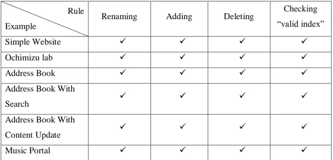
appendix 2. Moreover, these rules are also applied on some other examples from [25]. The results of the application are shown in table 1.
Rule Example
Renaming Adding Deleting Checking “valid index”
Simple Website
Ochimizu lab
Address Book
Address Book With
Search
Address Book With
Content Update
Music Portal
Table 1. The effectiveness of proposed rules on the examined models
The mark shows that the rule is valid on respective example and mark vice versal. It is true that the rules have worked on all of these examples.
38 | P a g e
Chapter 5 - Conclusions and future work
In conclusion, this study has examined some of the primary relationships between content model and navigation model used in UWE approach. Besides, the technique of representing explicit correspondences is proposed. Next, operational transformation rules have been constructed using the triple graph grammars. These rules are based on operations that users usually do such as renaming, adding, and deleting. Finally, an automatic plug-in tool has been proposed to illustrate the constructed rules.
Although the thesis has proposed a solution for synchronizing content model and navigation model of UWE approach, room for further development of a complete solution for synchronizing all models in UWE is available. First, other relationships than the relationship between content and navigation model such as the relationship among navigation model presentation model and process model should be investigated to construct a completely correspondence model. In addition, transformation rules can be built for the technique of constructing rule. Besides, a complete tool needs to be compiled to solve the synchronization problem systematically and automatically.
39 | P a g e
Bibliography
[1] Model Refactorings through Rule Based In-consistency Resolution. Ragnhild Van Der Straeten, Maja DHondt. 2006, In Proceedings of the 2006 ACM symposium on Applied computing.
[2] Model refactoring in web applications. Alejandra Garrido, Gustavo Rossi and Daminano Distante. Paris, France : WSE 2007 The 9th IEEE Symposium on Web Site Evolution Co-Located with ICSM, 2007.
[3] Challenges in Model Refactoring. Tom Mens and Gabriele Taentzer and Dirk Müller. s.l. : In: Proc. 1st Workshop on Refactoring Tools University of Berlin, 2007.
[4] Viewpoint Synchronization of UWE Models. Daniel Ruiz-Gonz´alez, Nora Koch, Christian Kroiss, Jos´e-Ra´ul Romero, and Antonio Vallecillo. San Sebastián, Spain : Proceeding in the Fifth International Workshop on Model-Driven Web Engineering (MDWE 2009) San Sebastián, June 22, 2009.
[5] From model transformation to incremental bidirectional model synchronization. Holger Giese and Robert Wagner. s.l. : Springer-verlag, 2008.
[6] Christian Kroiß and Nora Koch. The UWE Metamodel and Profile – User Guide and Reference Version 1.0. s.l. : Technical Report 0802- Germany, 2008.
[7] Unified Modeling Language version 2.0. OMG, 2005
[7] Towards Automatic Model Synchronization from Model Transformations. Y. Xiong, D. Liu, Z. Hu, H. Zhao, M. Takeichi, and H. Mei. s.l. : In ASE '07: Proceedings of the twenty-second IEEE/ACM international conference on Automated software engineering, 2007.
[8] Web Modeling Language (WebML): a Modeling Language for Designing Web Sites. Ceri, S., Fraternali, P., Bongio, A. s.l. : Proc WWW9 Conference, Amsterdam, NL, May 2000 (also in Computer Networks, 33 (2000), pp. 137-157).
[9] Ubiquitous Web Applications. UWA Consortium. Prague, Czech Republic : Proceedings of the eBusiness and eWork Conference, 2002.
[10] WSDM: A User-Centered Design Method for Web Sites. De Troyer O., Leune C. s.l. : Computer Networks and ISDN systems, Proc. of the 7th Int. WWW Conf. Elsevier, 1998.
[11] An Object-Oriented Approach to Automate Web Applications Development. Pastor, O., Abrahao, S.M., Fons, J. Munich, Germany : Proceedings of EC-Web 2001, 2001.
[12] An Object Oriented Approach to Web-Based Application Design. Theory and Practice of Object Systems. Schwabe, D., Rossi, G. s.l. : Wiley and Sons, 1998, Vol. 4(4).
[13] München, LMU – Ludwig-Maximilians-Universität. publicationsMetamodelAndProfile.html. http://uwe.pst.ifi.lmu.de. [Online]
40 | P a g e
[15] LMU – Ludwig-Maximilians-Universität München. exampleSimpleWebsite.html. http://uwe.pst.ifi.lmu.de/. [Online]
[16] Black Cats and Coloured Birds What do ViewpointCorrespondences Do? Linington, P. Maryland, USA : In Proc. of WODPEC 2007 , Oct. 2007.
[17] A relational approach to defining and implementing transformations between meta models. D. Akehurst, S. Kent, and O. Patrascoiu. 2003, Vol. Software and Systems modeling (SoSyM). [18] Consistency in Multi-Viewpoint Architectural . R.Dijkman. s.l. : University of Twente, 2006. [19] Realizing correspondences in multi-viewpoint specifications. Romero, J.R., Vallecillo, A. s.l. : In: Proc. of EDOC 2009, Auckland, New Zealand, IEEE CS Press, 2009.
[20] ISO/IEC. Information technology – Open distributed processing – Use of UML for ODP system specifications. s.l. : ISO and ITU-T, 2008. ISO/IEC IS 19793, ITU-T X.906.
[21] Specification of graph translators with triple graph grammars. Schurr, A. Herrsching, Germany : 20th International Workshop, June 1994.
[22] Incremental Model Synchronization with Triple Graph Grammars. H. Giese and R. Wagner. Genova, Italy : In Proc. Of the 9th International Conference on Model Driven Engineering Languages and Systems (MoDELS), Oct. 2006, Vol. volume 4199 of LNCS.
[23] Model Synchronization as a Problem of Maximizing Model Dependencies. Igor Ivkovic, Kostas Kontogiannis. s.l. : Proceedings of the International Conference on Information Technology, 2004. [24] Triple Graph Grammars: Concepts, Extensions, Implementations, and Application Scenarios. Paderborn, Germany : Department of Computer Science, June 2007.
41 | P a g e
Appendix 1
1. Presentation Package
The presentation model provides an abstract view on the user interface (UI) of a web application. It is based on the navigation model. The presentation model abstracts from concrete aspects of the UI, like the use of colors, fonts, and where the UI elements are placed on the web page; instead, the presentation model describes the basic structure of the user interface, i.e., which UI elements (e.g. text, images, anchors, forms) are used to present the navigation nodes (see Figure 1 and Figure 2). Also, the UI elements do not represent concrete components of any presentation technology but rather describe what functionality is required at that particular point in the user interface. This could simply mean that a text or image has to be displayed or for example that the user should be enabled to trigger a transition in the navigation model. In the last case, it is clear that an
Anchor would be used in the UWE presentation model, but UWE does not define how the
anchor should be rendered in the final web application. This could of course be just an anchor element of HTML (<a>), but also a button or even an embedded flash applet could serve the purpose.
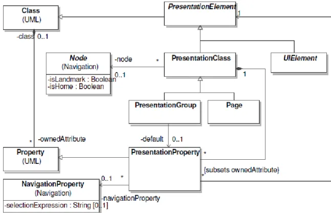
The basic elements of a presentation model are the presentation classes, which are directly based on nodes from the navigation model, i.e. navigation classes, menus, access primitives, and process classes. Presentation classes can contain other presentation elements. This is accomplished through presentation properties that use the included
presentation elements as type. In the case of UI elements, like text or image, the
presentation property is associated with a navigation property that contains the content to be rendered.
The inclusion of presentation classes into other presentation classes or pages leads to a tree of presentation classes that are shown together. This means that the links between their corresponding navigation nodes are effectively “followed automatically”. On the other hand, if two presentation classes do not belong to the same inclusion tree, then the link between their navigation nodes has to be triggered by user action.
In contrast to presentation classes and pages, a presentation group defines a set of
presentation classes that are shown alternatively, depending on navigation. In the sense of
42 | P a g e
Figure 1. The Backbone of the Presentation Package
Figure 2. Presentation Elements 1.1 Class Descriptions
43 | P a g e PresentationElement is the abstract super class of all model elements of the presentation
package.
Generalizations
Class (from UML)
Attributes
No additional attributes.
Associations
No additional associations. 1.1.2 PresentationClass
A presentation class defines the combination of presentation elements that show the contents of a navigation node. If the associated navigation node is reached, the complete composed content of the corresponding inclusion tree is shown.
Generalizations
PresentationElement on page 13 of reference [6]. Attributes
No additional attributes. Associations
node : Node [0..1] The navigation node that is rendered by the presentation class.
presentationProperty : PresentationProperty [*] {subsets ownedAttribute}
The collection of presentation properties that constitute the content of the
presentation class.