Masayoshi AIKAWA†a),Fellow andEisuke NISHIYAMA††b),Member
SUMMARY This paper describes very compact MIC magic-Ts and their integration with planar array antennas to realize the advanced antenna modules. The orthogonal transmission modes are effectively used to ar- range the preferable port layout of magic-Ts. This flexible port layout of magic-Ts is a practical feature for integration with planar array antennas.
The integration of magic-Ts and planar array antennas can easily create advanced functions. A couple of array antennas based on the integration advantages are introduced to materialize this technical concept. This in- tegration approach is of big worth to originate various kinds of advanced antennas and the wireless modules in the ubiquitous society.
key words:magic-T, planar antenna, array antenna, RF signal processing, integration, MIC
1. Introduction
This paper describes very compact MIC 180 deg. hybrid cir- cuits (called “magic-T” for short in this paper), and the inte- gration with planar array antennas to create advanced wire- less modules. Originally, a rectangular metallic waveguide hybrid circuit has been called “magic-T”. In the MIC tech- nology, a rat-race circuit and a phase-inverted hybrid ring [1] are known well as the MIC 180 deg. hybrid circuits. In addition to them, MIC magic-Ts are another kind of 180 deg. hybrid circuits that are composed of an in-phase com- biner/divider and an out-of-phase combiner/divider [2]. The attention here is focused on the essential features of the com- pact MIC magic-Ts to be integrated effectively with planar array antennas.
The planar array antennas have been progressing, be- cause they are small volume, light weight and very suitable to be integrated with semi-conductor devices and ICs [3], [4]. Moreover, they can be mass-produced at low cost, be- cause of the use of printed circuit technology. Moreover, various kinds of reconfigurable antennas have been investi- gated in recent years for the increasing demands of various wireless modules in the ubiquitous society [5]–[7].
MIC magic-Ts are nothing more than 180 deg. hybrid circuits. However, the integration with array antennas can create advanced and more functional antennas due to the multiplier effect of the integration. The authors took notice of the correlative RF signals on each array antenna element.
Needless to say, the correlative signals are very usual on Manuscript received May 25, 2012.
†The author is a professor emeritus of Saga University, Saga- shi, 840-8502 Japan.
††The author is with Saga University, Saga-shi, 840-8502 Japan.
a) E-mail: [email protected] b) E-mail: [email protected]
DOI: 10.1587/transele.E95.C.1560
a planar array antenna. The correlative RF signals, more specifically, the same amplitude signals with some phase difference, in-phase signals or out-of-phase signals, orthog- onal signals etc. are very suitable and effective for the di- rect RF signal processing for advanced array antennas. The magic-Ts can play the important and main roles for process- ing or preprocessing the correlated RF signals.
This paper firstly investigates the MIC magic-Ts from the viewpoint of both the circuit configuration and their cir- cuitry functions. As a result, very compact magic-Ts using the orthogonal transmission modes are introduced as well as their vectorial transformation. They are practically essential points to be integrated with planar array antennas. Espe- cially, their port layout and the compactness are regarded of major importance on the supposition that they are inte- grated with planar array antennas. In addition, the vectorial transformation of magic-Ts is also of importance from the point of view of RF signal processing. This vectorial trans- formation is very effective for processing the correlative RF signals on array antenna elements. Finally, a couple of ar- ray antennas based on the integration concept are schemat- ically presented to demonstrate the practical advantages of the concerned integration.
2. Magic-T and the Integration with Planar Array An- tenna
2.1 MIC Magic-T [2]
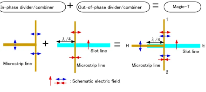
Magic-Ts are fundamentally composed of two kinds of com- biner/dividers, that is, an “in-phase combiner/divider” and an “out-of-phase combiner/divider”. That is generally the basic principle of 180 deg. hybrid circuits such as the con- ventional rectangular metallic waveguide Magic-T, rat-race circuit and phase-inverted hybrid ring, etc. Figure 1 shows
Fig. 1 Basic configuration of compact MIC magic-T.
Copyright c2012 The Institute of Electronics, Information and Communication Engineers
“Port E”, “Port H”, and “Port 1” & “Port 2”, respectively.
As shown in this figure, in addition to the in-phase combiner/divider (microstrip line T-branch), an out-of- phase combiner/divider is essential to compose a magic- T. In Fig. 1, RF signal input at Port E is divided out of phase to Port 1 and 2 via the slot-microstrip T-branch. On the other hand, RF signal input at Port H is divided in phase to Port 1 and 2 via the microstrip T-branch. There is no coupling between the two RF signals in principle, be- cause they are modally orthogonal to each other. Therefore, the in-phase dividing/combining and the out-of-phase divid- ing/combining are independently possible in a very wide frequency band [2]. They are also very precise vectorial transformations, “vectorial sum” and “vectorial difference”
operations for dual RF signals due to the symmetric config- uration.
The out-of-phase combiner/divider necessarily needs a balanced-mode transmission line such as slot line, coupled microstrip lines, coplanar waveguide (CPW) or the modi- fied coplanar waveguide. Figure 2 shows the cross sections of the CPW and the modified CPW. As for the coplanar waveguide and the modified coplanar waveguide, they can transmit the orthogonal transmission modes, so-called “odd- mode” and “even-mode”. This is possible by their symmet- ric structure of three conductor lines. As the odd mode is regarded as a kind of the balanced mode, the orthogonal modes can be used to form the various kinds of magic-Ts.
As shown in Fig. 2, the coplanar waveguide can be consid- ered to be a coupled slot line. The modified coplanar wave- guide can be also considered to be a coupled transmission line of a microstrip line and a slot line. The capability to transmit the orthogonal modes is very useful to arrange the port layout flexibly.
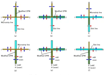
Figure 3 shows a couple of compact MIC magic-Ts. As for the types (a)∼(c), Port E and Port H are located at the opposite side to each other with respect to the Port 1 and 2. On the other hand, the types (d)∼(f) use the modified CPW as the orthogonal transmission modes. Consequently, their Ports E and H can be located on the same side with respect to the Port 1 and 2, as shown in this figure. This latter port layout is occasionally very effective to be integrated in practical microwave circuits planar array antennas.
Fig. 3 Compact MIC magic-Ts.
2.2 Compact MIC Magic-T and the Application to the Ar- ray Antenna
Magic-Ts described above are so compact and simple that they are very suitable to be integrated with planar array an- tennas. The remarkable features of the MIC magic-Ts are as follows,
(i) Dual RF signals can be processed individually with no coupling in principle due to the orthogonal mode be- havior.
(ii) The vectorial sum and the vectorial difference opera- tions can be very accurately done in high frequency band up to millimeter-wave band.
(iii) The design of magic-Ts is highly flexible, especially for the port layout and the kind of transmission lines.
(iv) The frequency characteristics are very wide, because the limit factor in these magic-Ts is mainly a quarter wavelength stub as shown in Fig. 1 and Fig. 3.
By the way, planar array antennas have been progress- ing in recent years for the increasing various demands in the ubiquitous society. It is caused by the above-mentioned features of small volume, lightweight, low cost and easy in- tegration with semiconductor devises and ICs. The main subject of this paper is the integration of the planar array antenna and the magic-T. The authors focused their concen- tration to the following points,
(i) Four features above of magic-Ts are very suitable and effective to process the correlative RF signals on array antenna elements.
(ii) Very compact magic-Ts shown in Fig. 3 are also very suitable for the integration with planar array antenna.
In the investigation, the authors took notice of the cor- relative RF signals on array antenna elements, namely, same amplitude signals, in-phase or out-of-phase signals, orthog- onal signals etc. The magic-Ts can be the most appropriate for processing or preprocessing these correlative RF signals.
As a result, the remarkable advantages of the integration can
Fig. 4 The advantages of the integration and their applications.
be found. They are outlined in Fig. 4 including the conse- quent application examples. Magic-Ts are mere 180 deg.
hybrid circuits. However, the integration with planar array antennas can create advanced functions and performances.
The practical advantages are as follows:
(1) Dual RF signals can be individually processed on the array antenna due to the orthogonal transmission mode behavior.
(2) The composing and decomposing of RF signals are ac- curately possible in a very wide frequency band, includ- ing DC in certain cases.
(3) Especially, the composing of the same amplitude RF signals into the orthogonal signals is practically effec- tive. The reverse decomposing is also useful in RF sig- nal processing on the array antenna.
(4) A magic-T is an excellent microwave “hybrid coil”
which are generally used in lower frequency bands. As a result, balanced type functional circuits such as double- balanced modulators are easily realized in microwave and millimeter-wave bands.
From the viewpoint of the applications to array anten- nas, the first advantage (1) is very effective to realize dual- band antenna, polarization diversity antenna and dual polar- ization transceiver, etc. The advantages (2) and (3) are also very attractive for the integration with array antennas such as beam steering array antenna, arrival angle sensing antenna, wide directivity angle rectenna, orthogonal polarization de- tection antenna, etc. In these applications, the crucial point is the vectorial transformation of the RF signals on array antenna elements. The vectorial sum and the vectorial dif- ference of RF signals can be operated very precisely and simultaneously in microwave and millimeter-wave bands, and vice versa. Therefore, this bilateral operation is use- ful especially to realize advanced array antenna such as a phased array antenna or various kinds of wireless sensors.
The schematic configurations and the basic behaviors of the array antennas integrated with magic-Ts are schematically described in the following section.
Fig. 5 Orthogonal polarization array antenna.
3. Array Antenna Integrated with Magic-T
As mentioned above, magic-Ts have noticeable features to be integrated with planar array antennas. In this section, several integration examples are schematically explained to demonstrate the promising and diversified potentiality of the integration.
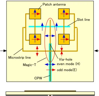
3.1 Orthogonal Polarization Array Antenna [8], [9]
Figure 5 shows an orthogonal polarization array antenna, where a magic-T is used as a RF power combiner/divider in the feed circuit. As the magic-T is composed of the or- thogonal transmission line, dual RF signals can be fed to the CPW individually. The even mode signal and the odd mode signal on the CPW correspond to the vertical polar- ization and the horizontal polarization, respectively as indi- cated by the arrows of the schematic RF signals. In the case of a transmitting antenna, the even mode signal and the odd mode signal are divided to the slot line and the microstrip line, respectively.
Figure 6 is also an orthogonal polarization slot ring ar- ray antenna, which is formed on a two-layer substrate. In this array antenna, two magic-Ts are perpendicularly located on layer 1 and layer 3, respectively. They provide their own port E (slot line) to each other, and then the dual RF signals can be fed with no coupling due to the effective use of the orthogonal transmission modes in the feed circuit.
3.2 Orthogonal Polarization Switchable Array Antenna [10]–[12]
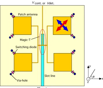
Figure 7 shows an orthogonal linear polarization switchable array antenna, where the magic-T is used to compose the
Fig. 6 Orthogonal polarization slot-ring array antenna.
Fig. 7 Orthogonal linear polarization switchable array antenna.
RF signal on the slot line and the diode switching voltage (Vcont.). The diodes loaded at the corners of the patch ele- ments are ON/OFF switched by theVcont., and then the po- larization angleφis orthogonally switched to+45 deg. or
−45 deg. linear polarizations. Needless to say, it can also receive the orthogonally polarized RF signal selectively.
Moreover, this array antenna can be used as an orthogonal linear polarization detection antenna, where the diodes di- rectly detect RF signals and the detected output is available atVdet.port.
3.3 Arrival Angle Sensing Array Antenna [13]
This is one of the typical applications to demonstrate the integration advantages, where the array antenna effectively
Fig. 8 Arrival angle sensing array antenna.
uses both the correlative RF signals on antenna elements and the precise vectorial operations of magic-Ts. In general, the received RF signals on each antenna element have the same amplitude with some different phase. The phase dif- ference is dependent mainly on the arrival angle. It is caused by the special coherency of uniform electromagnetic waves.
Figures 8(a), (b) and (c) show an arrival angle sensing ar- ray antenna, the RF signal processing flow and the vectorial expression, respectively. In this array antenna, two magic- Ts transform the received RF signals (#1, #2) into Σand Δsignals which are orthogonal to each other as shown in Fig. 8(c). The arrival angle on y-z plane can be simply cal- culated by the power ratio “Δ/Σ” and the antenna directivity, that is based on the monopulse radar principle. Moreover, this array can be used as a rectenna, which has a wide-angle directivity to use the vector sum together with the vector difference operations of the magic-T.
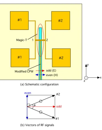
3.4 Beam Steering Array Antenna [14]
The reverse signal flow of the arrival angle sensing behavior shown in Fig. 8 is also true, because magic-Ts are passive and bilateral circuits. It means that the arrival angle sensing array antenna can be also used as a beam steering array an- tenna. Figure 9 shows the basic configuration of the array
Fig. 9 Beam steering array antenna.
antenna. In this case, the orthogonal RF signals (indicated by “even” and “odd”) are fed to an orthogonal mode trans- mission line (the modified CPW), and are composed into the same amplitude signals (#1, #2) with phase differenceφby the magic-T, as shown in Fig. 9(b). The phase differenceφ for the beam steering can be easily controlled by the RF sig- nal power ratio “even/odd”. These orthogonal RF signals (“even”, “odd”) can be easily generated by using a magic-T and a phase shifter on the reverse signal flow.
3.5 Double-Balanced RF Multiplier and Polarization De- tection Array Antenna [15], [16]
A magic-T is functionally equivalent with a “hybrid-coils”
that are generally used in lower frequency bands. On the other hand, balanced RF signals, namely out-of phase sig- nals can be naturally obtained in array antenna by using the mirror symmetric array antenna [17]. Therefore, a balanced RF multiplier on an array antenna can be very suitable cir- cuit for the RF signal processing.
For example, the orthogonal polarization detection ar- ray antenna can be simply achieved as shown in Fig. 10.
This figure shows a ring-coupled double-balanced multiplier and the application to an orthogonal linear polarization de- tection array antenna. The multiplier is composed of four compact magic-Ts and four diodes. The arrows in this fig- ure indicate the received RF signals including their relative phase relations. The multiplied output of the vertical and the horizontal RF signals is available at the center terminal
Fig. 10 Orthogonal polarization detection array antenna and the double-balanced RF multiplier.
of the multiplier based on the conventional ring-modulator principle. The balanced RF signals obtained on array anten- nas are practically suitable for the RF signal processing by such a balanced-type microwave circuit.
4. Conclusion
This paper described very compact MIC magic-Ts from the viewpoint of the port layout and the vectorial operation, and their integration with planar array antennas. The orthogonal transmission modes are effectively used to arrange the Port E and Port H at the same side with respect to the other two ports (Port 1 & Port 2). This particular port layout of magic- Ts is one of the practical features in integration with planar array antennas. In addition, the vectorial transformation of magic-Ts is also of importance for the direct RF signal pro- cessing. This vectorial transformation is very effective to enhance the functions of the array antenna and the wireless module.
The integration of magic-Ts and planar array antennas can create practical advantages that are very effective to de- velop the advanced array antennas. A couple of application
[4] Special Issue on Microstrip Antennas, IEEE Trans. Antennas Propag., Jan. 1981.
[5] F. Yang and Y. Rahmat-Samii, “Patch antennas with switching slots (PASS) in wireless communications: Concepts, designs, and appli- cations,” IEEE Trans. Antennas Propag. Mag., vol.47, no.2, pp.13–
29, 2005.
[6] Y. Zhang, B.Z. Wang, X.S. Yang, and W. Wu, “A fractal Hilbert mi- crostrip antenna with reconfigurable radiation patterns,” Proc. 2005 IEEE AP-S, vol.3A, pp.254–257, 2005.
[7] S.S. Yang, A.A. Kishk, and K.F. Lee, “Frequency reconfigurable U-slot microstrip patch antenna,” IEEE Antennas Wireless Propag.
Lett., vol.7, pp.127–129, 2008.
[8] F. Feng, E. Nishiyama, and M. Aikawa, “Linear polarization switch- able ring-slot array antenna using single-pole double-throw switch circuit,” IET Research Journal Microwave, Antennas and Propaga- tion, vol.5, no.2, pp.142–148, Jan. 2011.
[9] F. Feng, E. Nishiyama, and M. Aikawa, “Broad-band circularly polarized ring-slot array antenna for simultaneous use of the or- thogonal polarizations,” IEICE Trans. Electron., vol.E93-C, no.7, pp.1105–1110, July 2010.
[10] T. Onishi, Md. A. Hossain, E. Nishiyama, and M. Aikawa, “Polar- ization switchable microstrip array antenna using both-sided MIC technology,” 64th Joint Conference of Electrical and Electronics En- gineers in Kyushu, 10-1A-09, Sept. 2011.
[11] E. Nishiyama, M. Aikawa, and S. Sasaki, “Polarization switchable slot-ring array antenna,” IET Research Journals-Microwaves, An- tenna and Propagation, vol.2, no.3, pp.236–241, April 2008.
[12] Y. Ushijima, E. Nishiyama, and M. Aikawa, “A multi-element lin- early dual polarized microstrip array antenna with orthogonal feed circuit,” IEICE Trans. Commun. (Japanese Edition), vol.J94-B, no.9, pp.1181–1189, Sept. 2011.
[13] H. Sakai, E. Nishiyama, and M. Aikawa, “A study on arrival an- gle estimating array antenna,” IET Technical Report, vol.36, no.3, BCT2012-19, Jan. 2012.
[14] S. Mine, E. Nishiyama, and M. Aikawa, “Study on beam control- lable antenna by orthogonal excitation,” Proc. 2006 International Symposium on Antenna and Propagation, Singapore, Nov. 2006.
[15] S. Yoshimura, Y. Ushijima, E. Nishiyama, and M. Aikawa, “Mi- crostrip array antenna for orthogonal linear polarization discrimina- tion,” Proc. International Symposium on Antenna and Propagation, WeD1-2, Oct. 2011.
[16] M.A. Hossain, S. Yoshimura, E. Nishiyama, and M. Aikawa, “Planar array antenna for orthogonal circular polarization detection,” IEICE Technical Report, A·P2011-69, Sept. 2011.
[17] K. Egashira, E. Nishiyama, and M. Aikawa, “Planar array antenna using both-sided MIC’s feeder circuits,” IEICE Trans. Commun.
(Japanese Edition), vol.J86-B, no.5, pp.798–804, May 2003.
Techniques Society.
Eisuke Nishiyama was born in Saga, Japan.
He graduated from the department of Electron- ics, Saga University, in 1987, completed the M.S. program in 1989, and become a member of the technical staffthere. He has been a re- search associate since 1997. His research inter- est is planar antennas. He holds a Dr. Eng. de- gree, and is a member of IEEE.