5 Center for Liberal Arts and Sciences
No. 55(2020), 5–9
1. Introduction
To measure dose rates, we usually use a dosimeter with an ionization chamber and measure the incident dose for the object in several photon-counting energy-dispersive X-ray computed tomography scanners [1-4].
The energy dependence of sensitivity is small using the chamber, and several chambers [5,6] were developed corresponding to the radiographic objectives. However, the chamber-type dosimeter was expensive, and we developed several dosimeters using silicon photodiodes.
We constructed a semiconductor dosimeter with two photodiodes [7], and one diode is used to compensate for the energy dependence of the dosimeter. In this regard, the energy dependence of the ionization chamber is low, and it is easy to construct an ionization gap on the electric substrate instead of the chamber. In addition, the
a
Department of Physics, Iwate Medical University, 1-1-1 Idaidori, Yahaba, Iwate 028-3694, Japan
b
Department of Clinical Genetics, School of Medicine, Iwate Medical University, 2-1-1 Idaidori, Yahaba, Iwate 028-3694, Japan
c
Department of Radiology, School of Medicine, Iwate Medical University, 2-1-1 Idaidori, Yahaba, Iwate 028-3694, Japan
Eiichi SATO
a, Makoto ICHIKAWA
b, Taishi CHIBA
c, Yasuyuki ODA
a, Sohei YOSHIDA
c, Satoshi YAMAGUCHI
c, Kunihiro YOSHIOKA
cX-ray-dose-rate measurement using an ionization gap and a digital voltmeter
Abstract
To measure X-ray dose rate, we developed a dosimeter with an ionization gap. The ionization currents fl owing through the gap are converted into voltages using a current-to-voltage amplifi er and amplifi ed by a voltage-to-voltage amplifier. The amplifier output was measured using a digital voltmeter with a 1-s-timeconstant integrator for smoothing. The standard dose rate was measured using a readily available dosimeter with an ionization chamber and had a value of 103 μGy/s at a tube current of 1.0 mA and a tube voltage of 100 kV. Next, the absolute dose rate of the ionization gap was determined by one- point calibration at the same current and voltage conditions. Using the ionization gap, the dose rate was proportional to the tube current and was in proportion to the 2.8th power of the tube voltage.
(Accepted December 4, 2020)
Keywords:ionization gap, X-ray dose rate, digital voltmeter, operational amplifi er, noise reduction
6
amplifi er circuits in the photodiode dosimeter can be used to construct the ionization-gap dosimeter.
The major objectives of our research are as follows: to construct an ionization gap on the amplifier substrate, to reduce electric noises, and to measure the dose rate using a digital voltmeter. Therefore, we constructed an X-ray dosimeter with an ionization gap and measured the dose rates with changes in the tube current and voltage.
2. Experimental methods
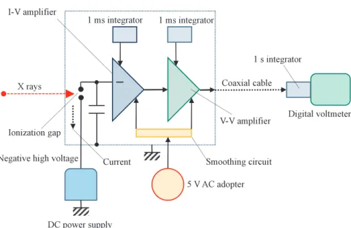
Figure 1 shows the block diagram including the electric circuit of an X-ray dosimeter using an ionization gap. The X rays are irradiated to the ionization gap, the ionization current fl owing through the gap is converted into voltage using a current-to-voltage (I-V) amplifi er with a 1-ms-timeconstant integrator, and the I-V output is amplified by a voltage-to-voltage (V-V) amplifier with a 1-ms integrator. Subsequently, the V-V output proportional to the dose rate is input to a digital voltmeter (Advantest, ADCE7351E). The applied voltages for the ionization gap were –100 and –200 V and were supplied using a DC power supply. The DC output of 5.0 V was supplied to dual operational amplifi er (Texas Instruments, LMC662) through a smoothing circuit. To reduce electric noises, we used a 1 nF ceramic condenser. Two amplifi ers and the ionization gap were set in a 1.5-mm- thickness aluminum (Al) box placed 1.0 m from the X-ray source.
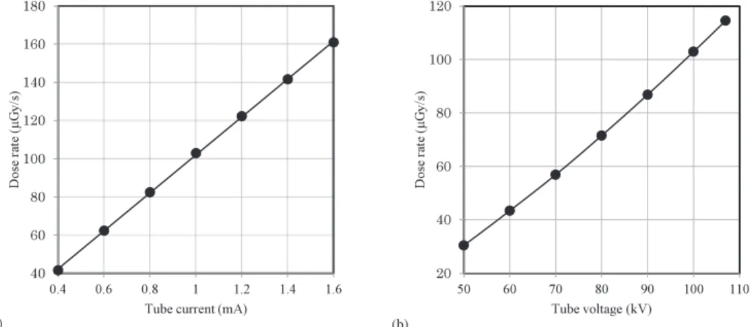
The absolute dose rate was determined using a dosimeter (Toyo Medic, RAMTEC 1000 plus) with an ionization chamber (Scanditronix, DC300) placed 1.0 m from the X-ray source. The ionization-gap was also set to 1.0 m from the source, and the dose rate was determined by one-point calibration at a tube current of 1.0 mA and a tube voltage of 100 kV.
Fig. 1 Block diagram including the electric circuit of the dosimeter with an ionization gap.
7 3. Results
The standard-absolute dose rates are shown in Fig. 2. The dose rate was proportional to the tube current, and the rate at a current of 1.0 mA and a voltage of 100 kV was 103 μGy/s [Fig. 2(a)]. The X-ray dose rate from a glass-window tube increased in proportion to the 1.7th power of the tube voltage using the rates of 50 and 100 kV [Fig. 2(b)].
Fig. 3 indicates the tube current dependence of the amplifier output and dose rate obtained using the ionization gap. The output was proportional to the tube current, and the offset voltage of 847 mV was determined by the intercept of the linear function at a tube current of 0 A [Fig. 3(a)]. Next, the dose rate increased in proportion to the tube current [Fig. 3(b)] and was 103 μGy/s at a tube current of 1.0 mA and a tube voltage of 100 kV.
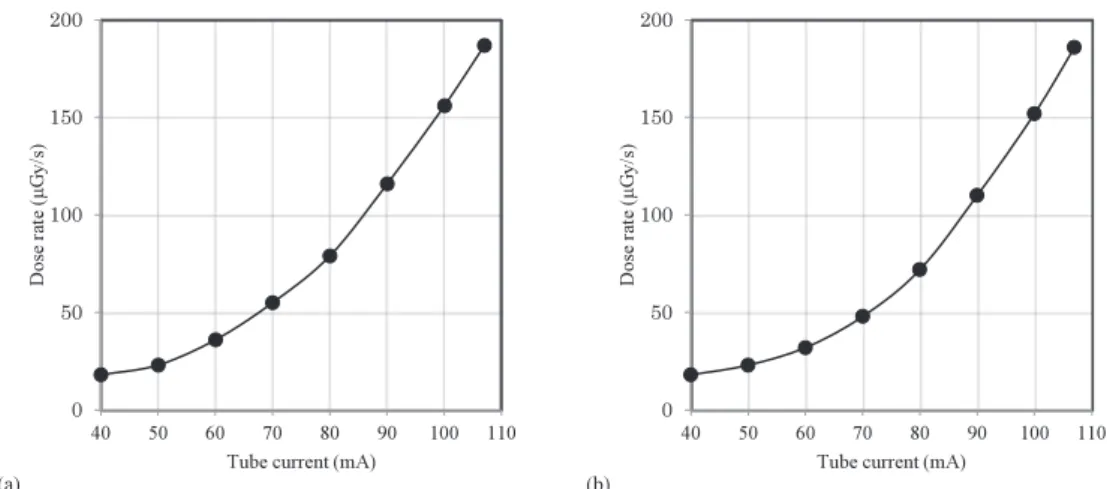
The tube voltage dependence of the dose rates measured using the ionization gap is shown in Fig. 4. At an applied voltage of –200 V, the dose rate increased in proportion to about the 2.8th power of the tube voltage using the rates at tube voltages of 50 and 100 kV [Fig. 4(a)]. At an applied voltage of –100 V, the dose rates Fig. 2 X-ray dose rates measured using a dosimeter with an ionization chamber. (a) Tube current dependence of the dose rate at a
tube voltage of 100 kV and (b) tube voltage dependence of the dose rate at a tube current of 1.0 mA.
Fig. 3 Variations of the amplifi er output and the dose rate with changes in the tube current at a tube voltage of 100 kV and an applied voltage of –200 V. (a) Amplifi er outputs and (b) calibrated dose rates.
8
showed the same characteristics [Fig. 4(b)].
4. Discussion
We used the ionization gap instead of the chamber and measured the dose rate. We measured the comparatively low rates of 103 μGy/s at a tube current of 1.0 mA and a tube voltage of 100 kV. Compared with a readily available I-V amplifi er, the 100 MΩ resistance in the I-V amplifi er for converting ionization current into voltage was small, and the resistance can easily be increased to 1 GΩ.
Using the ionization chamber, the dose rate was proportional to the 1.7th power of the tube voltage, since the chamber was high-sensitivity to low-energy photons. In contrast, the ionization gap could not detect low- energy photons easily due to the 1.5-mm-thickness Al shield box. And therefore, the dose rate increased in proportion to the 2.8th power of the tube voltage.
The offset voltage of the amplifi er system was 847 mV, and the offset should be minimized to increase the sensitivity. Next, we are constructing a parallel ionization gap and are interested in the sensitivity variations with changes in the parallel-gap length.
In conjunction with the microcomputer, a long USB cable and a PC, a convenient dosimeter using an ionization gap can be constructed. Therefore, this ionization-gap dosimeter can be used for physical experiments in medical university, except for high-precision dosimetry.
5. Conclusions
We constructed an X-ray dosimeter with an ionization gap and measured the dose rate with changes in the tube current and voltage. The dose rate was proportional to the tube current at a tube voltage of 100 kV. The rate increased in proportion to the 2.8th power of the tube voltage at a tube current of 1.0 mA. The dose rate seldom varied at applied gap voltages beyond 100 V.
Acknowledgments
This work was supported by Grants from JSPS (17K10371, 17K09068, 17K01424, and 17H00607). This was also supported by a Grant-in-Aid for Strategic Medical Science Research (S1491001 and 2014-2018) from
Fig. 4 X-ray dose rates with changes in the tube voltage at a tube current of 1.0 mA (a) at an applied voltage of –200 V and (b) an applied voltage of –100 V.
9 the Ministry of Education, Culture, Sports, Science and Technology of Japan.
References
[1] Sato, E., Kosuge, Y., Yamanome, H., Mikata, A., Miura, T., Oda, Y., Ishii, T., Hagiwara, O., Matsukiyo, H., Watanabe, M., Kusachi, S., “Investigation of dual-energy X-ray photon counting using a cadmium telluride detector with dual-energy selection electronics,” Rad. Phys. Chem. 130, 385–390 (2017).
[2] Matsukiyo, H., Sato, E., Oda, Y., Ishii, T., Yamaguchi, S., Sato, Y, Hagiwara, O., Enomoto, T., Watanabe, M., Kusachi, S., “Investigation of quad-energy photon counting for X-ray computed tomography using a cadmium telluride detector,” Appl. Radiat. Isot. 130, 54–59 (2017).
[3] Moriyama, H., Sato, E., Oda, Y., Yoshida, S., Hagiwara, O., Enomoto, T., Watanabe, M.: Measurement of humanbody-window spectra using a white power light-emitting diode and its application to high-spatial- resolution computed tomography. Proc. SPIE 11073, 1107321-1–6 (2019).
[4] Yoshida, S. , Sato, E ., Oda, Y ., Yoshioka, K ., Moriyama, H ., Watanabe, M.: Triple-sensitivity high-spatial- resolution X-ray computed tomography using a cadmium-telluride detector and its beam-hardening effect.
Appl. Radiat. Isot. 159, 109089 (2020).
[5] AlMasri, H., Funyu, A., Kakinohana, Y., Murayama, S., “Investigation of thermal and temporal responses of ionization chambers in radiation dosimetry,” Rad. Phys. Tech. 5, 172–177 (2012).
[6] Kato, T., Arai, K., Sagara, T., Kato, R., Yamazaki, Y., Oyama, S., “Patient-specific quality assurance for proton depth dose distribution using a multi-layer ionization chamber in a single-ring wobbling method,”
Rad. Phys. Tech. 12, 305–311 (2019).
[7] Sato, E., Oda, Y., Sagae, M., Yoshida, S., Yamaguchi, S., Sato, Y., Moriyama, H., Hagiwara, O., Matsukiyo, H., Enomoto, T., Watanabe, M., Kusachi, S., “High-sensitivity compact dosimeter using two silicon X-ray diode,” Ann. Rep. Iwate Med. Univ. Center Lib. Arts Sci. 53, 7–12 (2018).