PAPER
Special Section on the Architectures, Protocols, and Applications for the Future InternetA Dynamic Channel Switching for ROD-SAN
Daiki NOBAYASHI†a), Yutaka FUKUDA†, Kazuya TSUKAMOTO†,andTakeshi IKENAGA†,Members
SUMMARY Wireless sensor and actuator networks (WSANs) are ex- pected to become key technologies supporting machine-to-machine (M2M) communication in the Internet of things (IoT) era. However, sensors must be able to provide high demand response (DR) levels despite severely lim- ited battery power. Therefore, as part of efforts to achieve a high DR, we are working on research and development related to radio-on-demand sensor and actuator networks (ROD-SANs). ROD-SAN nodes are equipped with wake-up receivers that allow all nodes to stay in sleep mode for a long pe- riod of time, and transmit only after the receiver receives a wake-up signal.
In addition, sender nodes can direct the receiver nodes to switch commu- nication channels because the wake-up signal also includes information on the channel to use for communication between each other. However, as the number of nodes utilizing the same channel increases, frequent packet col- lisions occur, thereby degrading response performance. To reduce packet collisions, we propose an own-channel-utilization based channel switching (OCS) scheme, which is a modification of the average-channel-utilization based switching (ACS) as our previous works. The OCS scheme decides whether or not to switch channels based on a probability value that con- siders not only average-channel utilization of nearby nodes but also own- channel utilization. This approach permits node switching to other chan- nels by considering the overall utilization states of all channels. In this paper, based on simulations, we show that our scheme can improve the delivery ratio by approximately 15% rather than ACS scheme.
key words: wireless sensor and actuator networks, ROD-SAN, channel switching
1. Introduction
Wireless sensor and actuator networks (WSANs) are ex- pected to become key technologies supporting machine-to- machine (M2M) communication in the Internet of things (IoT) era. In use, WSANs often form multi-hop networks because it is necessary to collect an assortment of data pack- ets over broad areas. For example, in the electric power industry, WSANs are often applied to smart grids, which control energy based on information obtained by smart me- ters. However, since it is important to achieve a demand re- sponse (DR) level that balances energy supply[1]in smart grids, WSANs must be capable of implementing rapid con- trol changes. Additionally, power saving is also an impor- tant factor because WSAN sensors must collect and manage various data under severely restricted battery power condi- tions. Therefore, WSANs need the ability to provide both high response performance and power saving functions si- multaneously.
Manuscript received August 16, 2018.
Manuscript revised December 17, 2018.
Manuscript publicized February 21, 2019.
†The authors are with the Kyushu Institute of Technology, Kitakyushu-shi, 804–8550 Japan.
a) E-mail: [email protected] DOI: 10.1587/transinf.2018NTP0007
In duty cycling, which is currently the most popu- lar power saving scheme in WSAN management, sensors periodically cycle through active and sleep states, thereby drastically improving power saving by holding sensors in sleep mode whenever possible[2]–[5]. However, even as power saving performance is improved, long sleep inter- vals can significantly decrease response performance. In other words, duty cycling schemes attempt to trade-offthe problems of power saving and response performance. On the other hand, the use of multiple channels is an effective way to achieve high response performance levels in wire- less sensor networks (WSNs)[6]–[12]. Although all these schemes can improve response performance, they do not consider asynchronous communication which requires addi- tional procedures in WSANs, such as when the control side of a WSAN suddenly sends a control message to actuators.
To appropriately balance power saving and high re- sponse performance, we are working on research and de- velopment of radio-on-demand sensor and actuator network (ROD-SAN) technology[13],[14]. All ROD-SAN nodes are equipped with a wake-up receiver and normally stay in sleep mode until activated by a wake-up signal. Since this wake-up receiver performs at ultra-low power, power con- servation is improved. In other words, a ROD-SAN node can reduce the power consumption and accumulates surplus energy by operating on-demand between an active mode and a sleep mode compared with duty-cycling. Moreover, our previous studies showed that our scheme can extend the net- work lifetime while providing quick response by the actua- tion commands[15].
Additionally, the wake-up signal can also include node identification and communication channel information[15].
As a result, when necessary, a pair of sender and receiver nodes can switch to other channels after sending and re- ceiving their individual wake-up signals. However, frequent packet collisions often occur even in the case of ROD-SANs that can flexibly change channels. One factor that is respon- sible for this problem is that multiple ROD-SAN nodes, op- erating autonomously, can select the same channel simulta- neously. The other is that, with the growth and spreading of IoT technology, various communication standards have resulted in overcrowding of signals in the same frequency band. Wide range communication using low-power wide area (LPWA) technologies affect not only ROD-SAN sys- tems, but also the majority of other wireless communication networks, and thereby increase the likelihood of packet col- lisions. Therefore, it is clear that an efficient channel switch- Copyright c2019 The Institute of Electronics, Information and Communication Engineers
ing scheme based on ROD-SAN technology can be expected to reduce the frequency of packet collisions.
In our previous studies, we proposed an average- channel-utilization-based channel switching (ACS) scheme[15], and evaluated the performance of multi-hop communication using that scheme[16]. In our ACS scheme, a sender node can change channels stochastically based on the utilization rate of each channel and the average utiliza- tion of all available channels. More specifically, sender nodes that are connected to channels experiencing high uti- lization will stochastically switch to low utilization chan- nels, thereby reducing the potential for packet collisions.
However, since the ACS scheme does not take into consid- eration the influence on the channel after the sender node switches, such switching operations can actually destabilize the destination channel and cause further performance dete- rioration.
In the present paper, we propose an own-channel- utilization-based channel switching (OCS) scheme, which is a modified version of the previous method[15]. An impor- tant characteristic of the proposed scheme is that wake-up receiver has the ability to monitor data frame transmissions on all channels. The OCS scheme measures the utilization of each channel using the wake-up receiver, and the sender node then calculates the average channel utilization ratio for all channels before transmitting data packets. Each node then calculates a probability based on the average channel utilization ratio and own channel utilization ratio to avoid imposing a significantly high load on a particular channel, and decides autonomously whether to switch channels based on this calculation. Since sender nodes select channels that will not exceed average channel utilization levels, each node can use all channels equally, and concentration on a specific channel is avoided. In this paper, we will demonstrate the ef- fectiveness of our scheme by reporting on the results of sim- ulations conducted to evaluate communication performance in terms of delivery ratio and fair use of each channel.
The remainder of this paper is organized as follows.
In Sect. 2, we provide an overview of the ROD-SAN and describe the wake-up receiver, which is the most important element of ROD-SAN technology. In Sect. 3, we introduce related studies on channel reassignment, and then present an outline of the proposed scheme in Sect. 4. In Sect. 5, we show the simulation results obtained through the proposed scheme. Finally, in Sect. 6, we give our conclusions.
2. Radio-onDemand Sensor and Actuator Networks (ROD-SAN)
We have developed and implemented the ROD technolo- gies[13], [17] based on the IEEE 802.11 standard. Our scheme can achieve both power saving and high responsive- ness by running a sleeping access points (APs) with a wake- up receiver in order to perform wake-ups using a signal of existing wireless LAN. Therefore, the ROD technology pro- posed previously is applied to WSAN (i.e., ROD-SAN tech- nology)[14]. In this section, we describe how to extend the
basic concept of ROD technologies to ROD-SAN.
2.1 Extension for ROD-SAN from ROD Technologies We developed a wake-up receiver operating in the 920 MHz frequency band. The characteristics of the ROD-SAN tech- nology are as follows:
• The wake-up receiver is dedicated to detecting the data frame length.
• The wake-up receiver can operate at very low power consumption (0.5 mW or less).
• The wake-up receiver can detect the wake-up signal on the entire 920 MHz bands.
• The node can transmit the wake-up signal on any chan- nel (without synchronization between a sender and a receiver.)
• A sleeping node equipped with a wake-up receiver switches to active mode whenever a wake-up signal is received from the sender.
• The wake-up signal includes the ID of the activating node, and is constructed of three frames. The wake-up receiver can determine this ID based on the length of the three frames.
• To send the wake-up signal, the node does not need a particular module, but instead uses the originally sup- plied transmission module (only a firmware update is necessary).
Note that there are many approaches using wake-up radio in order to achieve communication on demand[18]. ROD- SAN always consumes ultra-low power for wake-up re- ceiver, but ROD-SAN can achieve higher responsiveness than existing wake-up approaches combining duty cycle.
Furthermore, because the existing approaches requires an interface for transmitting the wake-up radio, the ROD-SAN which does not require it has the potential for scalability.
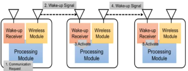
Figure 1 shows the ROD-SAN wake-up processing procedure. First, if a communication request occurs at a sender, that sender transmits a wake-up signal to the tar- get receiver that is in sleep mode. When the wake-up re- ceiver on the target receiver detects the wake-up signal, it in- structs the processing module to switch to active mode, and the node then transmits an acknowledgment of the wake- up instruction to the sender node. When the sender node receives the acknowledgment from the target node, it then transmits the data packets. After these communication pro- cedures have been completed, both the sender and receiver
Fig. 1 Wake-up processing.
can switch back to sleep mode. By repeating this pro- cess, ROD-SAN can achieve both power saving and high re- sponse performance levels even in multi-hop environments.
Since the power saving performance of ROD-SAN is evalu- ated by[14], it is omitted in this paper.
2.2 Challenges for ROD-SAN
ROD-SAN nodes can reduce needless power consumption by the use of a wake-up receiver, and can achieve a quick response to communication by on-demand access.
However, ROD-SAN may cause a performance degra- dation for packet delivery when a significant number of nodes are located within a small area, such as a smart town.
This means that packet losses and transmission delays can increase due to multiple packet collisions between sensors and actuators. Additionally, ROD-SAN nodes should use the carrier sense multiple access with collision avoidance (CSMA-CA) scheme because the nodes frequently switch between active and sleep modes as a response to requests from the sender node. As a result, frequent retransmissions occur due to the multiple packet collisions, and sensors ex- perience needless consume power as the number of retrans- missions increases.
Therefore, we focus on a channel switching scheme us- ing multiple channels for ROD-SANs to reduce packet col- lisions.
3. Related Works
A number of channel assignment schemes that use multiple channels to solve interference-related performance degrada- tion problems have been proposed[19]–[21]. However, it is difficult for WSANs to use multiple channels simultane- ously because their sensors typically have only one commu- nication interface. Thus, channel assignment schemes that utilize centralized and distributed approaches to scheduling have also been proposed.
Centralized channel assignment schemes, MCRT[22], MODESA[23] can statically or dynamically assign chan- nels in order to optimize performance. However, their scal- ability is limited because these schemes must be able to use network topology information such as link states and node positions. Distributed channel assignment schemes have also been reported[24],[25]. This scheme proposed by Phung et al.[24] achieves multi-channel efficiency by means of scheduled channel hopping. Additionally, since these are receiver-based channel assignment schemes, it is necessary to adjust the channels of one or more sender nodes to match the receiver node, which makes it difficult to al- leviate channel interference in situations where numerous sender nodes exist. Furthermore, both channel synchro- nization overhead and power consumption will increase be- cause there is no mechanism to facilitate physical channel switching, and node power consumption for optimum chan- nel assignment will increase if the calculations are complex.
Thus, a simple procedure is needed for both channel assign-
ment and switching.
RM-MMAC[26], which is a reservation based multi- channel protocol, works by assigning a channel to each link in order to avoid channel interference among sender nodes.
However, when each sender uses a different channel, re- ceivers must switch channels frequently, thereby resulting in a sizable overhead in terms of power consumption and delivery delay. Furthermore, strict time synchronization is needed to coordinate between sender and receiver nodes be- cause link-based channel assignment protocols switch chan- nels based on a predetermined schedule. Therefore, the power saving performance may decrease since the sensors need to engage in continuous monitoring. Finally, while such protocols work to prevent nodes in a single wireless sensor network from interfering with each other, they do not consider interference from other networks using the same frequency band.
TMCP[27]is tree-based multiple channel assignment scheme. TMCP allocates different channels to each tree con- structed by multiple sensors and thus improves throughput and delivery ratio. Although TMCP can alleviate the inter- flow interference among trees, it does not consider to the intra-flow interference between multihop communication in the tree. To improve the efficient performance in multihop wireless communication, effective channel switching per a node (hop) is required to achieve not only low power con- sumption but also transmission delay.
Taking all of the above into consideration, it was felt that channel switching and assignment schemes in ROD- SAN must satisfy the following requirements:
• Provide dynamic and distributed link-based channel as- signment.
• Use simple channel synchronization of sender and re- ceiver nodes without time synchronization.
• Show consideration for other networks that use the same frequency, and facilitate fair channel usage.
• Realize channel switching per each node in multihop communication.
4. Proposed Scheme
In this section, we propose a channel switching scheme that addresses all of the abovementioned problems. We begin by extending the ROD-SAN wake-up function in Sect. 4.2 and introducing our previous work in Sect. 4.3, and then outline our newly proposed scheme in Sect. 4.4.
4.1 Assumption
The wake-up receiver effectively saves the power consump- tion by using the envelope detection that can be imple- mented as the simple circuit such as a passive band path filter (BPF). The wake-up receiver in ROD-SAN mounts the BPF corresponded to wide bandwidth (MHz levels), and it can detect the whole channel for 920 MHz bands. There- fore, if the envelope detection of each channel in 920 MHz
bands can be achieved by using passive BPF for narrowband (100 or 200 kHz), channel efficiency of ROD-SANs can be improved. However, there is no passive BPF correspond- ing to narrowband currently. In anticipation of future tech- nological progress, we strongly believe that the detection capability of all channels can also be achieved by the in- troduction of the passive BPF corresponded to narrowband in this paper. Since the power consumption of the BPF is substantially zero, we assume that detection of all channels can maintain low power consumption without a significant increase in the power consumption of the wake-up receiver.
As a result, we add the following feature for ROD-SAN Wake-up Technology in this paper.
• The wake-up receiver can detect all channels available in the 920 MHz band simultaneously.
4.2 Extension of Wake-up Function in ROD-SAN for Multiple Channel Correspondence
When sensors use different channels in WSANs and ROD- SANs, both the sending and receiving nodes must synchro- nize the channel with each other before starting communi- cation. These synchronizing functions are necessary in or- der to realize an autonomous and distributed channel assign- ment protocol for WSANs. However, message exchange for the synchronizing channels increases power consump- tion because each node must send and receive superfluous data that consumes unnecessary power. Thus, it is difficult to apply autonomous (dynamic) channel assignment protocol that need to synchronizing channels to traditional WSANs and ROD-SANs. Accordingly, we focus on the ROD-SAN wake-up functions (wake-up receivers and signals) in an ef- fort to modify the functions that facilitate channel synchro- nization while maintaining power economy.
In particular, we add a frame to specify a channel for the wake-up signal that activates the node. As described in Sect. 2, the wake-up receiver is capable of detecting frame lengths. Thus, a sending node transmits three frames for identifying the node to be activated in the existing ROD- SAN. The node receiving the signal performs node identifi- cation from those three frames, and then switches to active mode if it is the addressee node. In our proposal, we focus on this function and add a modification to include wake-up channel information to the wake-up signal. In other words, a one-frame channel identification is added to the existing three frames node identification. The node that receives the wake-up signal with the channel identification changes to active mode, and switches to the specified channel. This method can reduce the overhead for synchronization be- tween sending and receiving node.
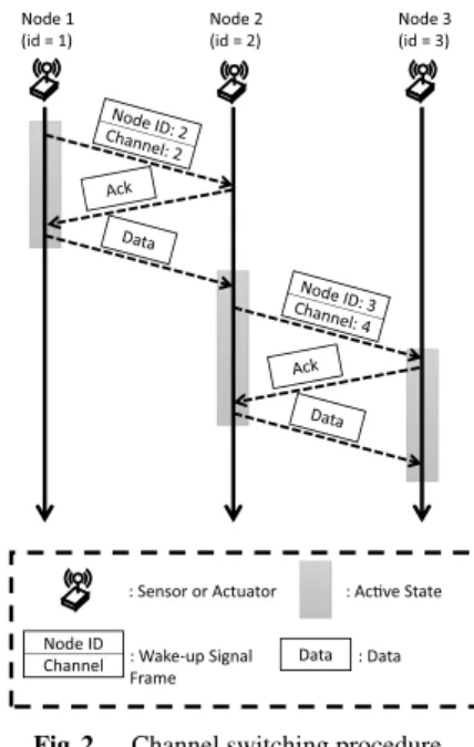
Figure 2 shows the ROD-SAN channel switching pro- cedure in the case of transmitting data from Node 1 to Node 3 via multi-hop communication. First, Node 1 transmits the frames containing both the wake-up ID (Node ID: 2) and channel ID (Channel: 2) as a wake-up signal to Node 2.
When the Node 2 wake-up receiver detects the wake-up sig-
Fig. 2 Channel switching procedure.
nal from Node 1 and determines that the signal is addressed to itself, it activates the processing module of Node 2 and Channel 2 of the wireless module. Then, Node 1 sends the data frame on Channel 2. If the data transmission is suc- cessful, Node 1 then switches to sleep mode. Node 2 also transmits frames for both the wake-up ID (Node ID: 3) and channel ID (Channel: 4) as a wake-up signal to Node 3, and then forwards the data frame received from Node 1 to Node 3. When Node 3 receives the wake-up signal, it can receive the data packet by switching to Channel 4 based on the re- ceived signals. Then, Node 2 switches back to sleep mode because its role is finished.
4.3 Previous Work: ACS
Previously, we proposed the average-channel-utilization- based channel switching (ACS) scheme[15]and evaluated its performance for multi-hop communication[16]. In the ACS scheme, a sender node can switch the transmission channel stochastically based on the utilization of each chan- nel and the average utilization of all available channels. To accomplish this, each node uses the wake-up receiver to periodically calculate the utilization ratio for each channel (uch), and then calculate the average utilization from the re- sults for all channels (uave). Each node then decides whether or not to switch using a probability (p) that is calculated based onuchanduave, via following equation as
p=uch−uave
uch . (1)
The node randomly selects a channel to use, which is less thanuave, in order to disperse the load.
Using this process, the ACS scheme can equalize traffic over all available channels and reduces the chances of packet collisions in environments where all nodes use the same data rate, and timing. However, this scheme cannot use all chan-
nels equally when there are different transmission nodes op- erating in the neighborhood because the ACS protocol does not consider the influence on the channel after a sender node switches to a new channel. This means that the load on the new channel may drastically increase if a node with a high transmission rate switches to other channels. For this rea- son, channel switching scheme for ROD-SAN is required as below: (a) the scheme will allow all nodes to use the channels equally, and (b) the scheme can reduce packet col- lisions in environments where the data transmission rate of each node is different.
4.4 Proposed Scheme: OCS
In order to resolve the above issues, herein we propose the OCS scheme, which is an enhanced version of the ACS scheme. The OCS scheme decides whether or not to switch channels based on a probability value that considers own- channel utilization.
4.4.1 OCS Procedure
First, as previously mentioned, all ROD-SAN nodes mon- itor the utilization of all channels by using their wake-up receivers at given periods. As described in Sect. 2, by in- stalling an efficient and straightforward filter, wake-up re- ceivers can measure signals on all channels simultaneously.
Furthermore, because the wake-up receiver can judge the strength of the received radio waves, it can also detect radio waves of all communication protocols, which makes it pos- sible to calculate the utilization of each channel in the vicin- ity. Note that the wake-up receiver has a memory to store a length of a communication signal per channel. Although the processing module of the node is a sleep mode, the wake-up receiver can store the length of a communication signal in the memory in the same way that it detects the length of the wake-up signals. The node calculates the channel utilization of each channel using the information stored between the sleep mode whenever the node needs the channel utilization in an active mode. Thus, the node can store information for calculating channel utilization for all channels while main- taining low power consumption, even though the processing module is sleeping.
In our proposed scheme, each node individually calcu- lates the channel utilization ratio of each channel based on the signals received by the antenna of the wake-up receiver, because the signals that can be sensed by each node are dif- ferent depending on the location of the node. The wake-up receiver on each node can collect and store utilization infor- mation for each channel per a given interval even when the node is in the sleeping mode in order to determine the usage status of all other channels. Figure 3 shows the overview of calculation of channel utilization ratios for each channel.
For example, each node calculates and stores the channel utilization ratioch ui(t),i∈N(iis the channel number,Nis the set of available channels), in period of cycletth.
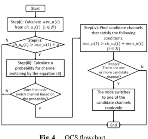
Figure 4 shows the channel switching algorithm. The
Fig. 3 Calculation of channel utilization ratios.
Fig. 4 OCS flowchart.
channel switching action performs only at the first frame transmission of each cycle because a channel switching for each frame increases the overhead for channel switching significantly. In other words, the transmission channel for each node is determined for each cycle based on the channel switching algorithm. The node operates using the channel switching algorithm shown in Fig. 4 and the steps below.
Step (i): Calculating the average utilization: The node calculates the average channel utilization ratioave u(t) from the utilization values for each channel ch ui(t). The ave u(t) shows a metric for the communication traffic in the space at periodt, andnindicates the maximum number of available channels. The node calculates the average channel utilization ratio as a criterial metric using below as
ave u(t)= 1 n
n
i=1
ch ui(t). (2)
Step (ii): Determining whether or not to switch channel: The node determines whether or not to switch the channel based on the channel load. Specifically, the node compares theave u(t) and the utilization of channelo(ois the channel used by the node),ch uo(t). Ifch uo(t) is lower thanave u(t)+α, the node determines that the channel load ois small and the probability of packet collisions is low, so it does not switch the channel. On the other hand, ifch uo(t) is higher thanave u(t)+α, the node determines that the chan- nel load o is large, and that the probability of packet col- lisions is high. At that time, the node decides to perform
Table 1 Comparison of power saving and channel assignment schemes
ROD-SANs
Traditional WSANs Original ACS OCS
On-demand wake-up and sleep ×
Channel synchronization per a frame × ×
Channel assignment based on average chan- nel utilization ratio
× ×
Channel assignment based on average and own channel utilization ratios
× × ×
channel switching and proceeds to Step (iii). αrepresents the allowance used to prevent excessive channel switching.
Step (iii): Calculating the probability of switching to another channel: In this step, the node calculates the probability of switching to another channel based on the ob- tained utilization values in order to prevent concentration in one channel. Since each node operates autonomously, if all the switching nodes shift to another channel simultane- ously, the nodes are likely to concentrate in one channel and increase its load. Thus, each node calculates a probability to determine if it should switch to another channel,p(t), based onave u(t),ch uo(t), and the channel utilization value used by the node itself (own u(t)).
p(t)=dif f uo(t)
ch uo(t) (1−own u(t)
ch uo(t)) (3)
where dif f uo(t) is the excess of ch uo(t) over ave u(t) (dif f uo(t)=ch uo(t)−ave u(t)).
In (3), dif f uo(t)/ch uo(t) indicates the recommended rate for switching to another channel in channelo, whereas (1−own u(t)/ch uo(t)) represents a weight based on the oc- cupancy ratio that the node occupies in channelo. Here, it should be noted that nodes with large channel occupancy rates are suppressed from switching to other channels be- cause there is a strong probability that such switching would simply result in high utilization of the destination channel.
For that reason, it is preferential that nodes with lower trans- mission rates switch to other channels.
Step (iv): Finding a destination channels to switch to: A node that has decided to switch to a different channel finds a destination channel, and selects a channel in which the sum ofown u(t) andch ui(t) (i ∈ N) does not exceed ave u(t).
Step (v): Determining the destination channel: If there are multiple destination channels available, the node makes a random selection from among them. Finally, the node transmits a wake-up signal with the ID of the receiving node and selected channel, and then sends the data frame.
We found that the scheme described above provides an effective channel switching method for existing ROD- SAN nodes in order to improve both overall performance and power conservation characteristics by reducing packet collisions.
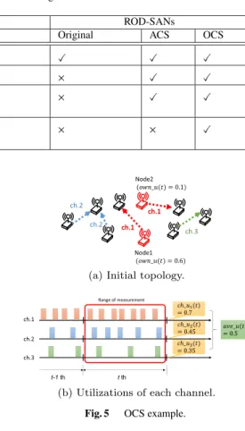
Finally, Table 1 summarizes the comparison of power saving and channel assignment scheme among traditional
Fig. 5 OCS example.
WSANs, Original ROD-SANs, ACS and OCS. Traditional WSANs is difficult to achieve power saving and high re- sponsivity simultaneously. In contrast, original ROD-SANs can reduce power consumption, while providing high re- sponsivity by changing flexibly between sleep mode and ac- tive mode. However, they may suffer performance degrada- tion due to channel collisions where many nodes at the same place coexist on the same channel. ACS extends the chan- nel assignment scheme for ROD-SAN, and it can achieve to specify a channel by each frame when a node transmits wake-up signal. A ROD-SAN node using ACS can select an appropriate channel based on average channel utilization ratio. However, ACS has a potential to degrading the per- formance because the effect of the utilization imbalance be- tween its own channel and others is ignored. On the con- trary, OCS is an enhanced version of ACS. In OCS, an ap- propriate channel is reliably selected by considering the ef- fect of the utilization imbalance between its own channel and others can be considered. As a result, OCS success- fully improves the communication performance while main- taining not only power saving but also high responsivity.
Furthermore, our channel switching procedure operates af- ter each node receives the wake-up signal, so the procedure does not affect the power saving performance.
4.4.2 OCS Operation Example
Figure 5 shows an example of OCS processing, whereas
Fig. 5 a presents the initial topology. We assume that there are three available channels and that the communications of each node can reach all other nodes. In this example, each node uses one of three available channels, hereafter desig- nated Channels 1 to 3, and we focus on the procedure for Nodes 1 and 2.
Nodes 1 and 2 transmit a data frame using Channel 1.
Each node periodically monitors the utilization states of all channels by using the wake-up receiver. The monitoring sta- tus is shown in Fig. 5 b. Each node calculates the channel utilization ratioch ui(t) for each channel in a period of cy- cletth. In this example,ch u1(t),ch u2(t), andch u3(t) are 0.7, 0.45, and 0.35 respectively. Furthermore, the average channel utilization ratioave u(t) can be calculated as 0.5.
Thus, Nodes 1 and 2 self-select themselves as candidates for channel switching becausech u1(t) is higher thanave u(t).
Next, Nodes 1 and 2 calculate the probability for chan- nel switching based on (3). If the channel utilization ratio for Node 1own u(t) is 0.6, and that for Node 2own u(t) is 0.1,p(t) of Node 1 and Node 2 are approximately 0.04 and 0.24, respectively.
Here, we assume that, based on its probability value, Node 2 has self-selected to switch to another channel and must find a destination channel. When Node 2 examines Channel 2 prior to switching, it determines that the utiliza- tion of that channel after switching would be approximately 0.55, which means that Channel 2 cannot be selected be- cause the utilization would exceedave u(t). On the other hand, when Node 2 examines Channel 3 prior to switch- ing, it determines that the utilization of that channel after switching would be approximately 0.45. As a result, Node 2 switches from Channel 1 to Channel 3 because the utiliza- tion value is lower thanave u(t).
By controlling channel switching based on periodic evaluation of these probability, each node can effectively utilize the channels available in autonomous and decen- tralized WSANs. As a result, each node in a ROD-SAN autonomously reduces packet collisions, thereby achieving both high response and power saving performance rates.
5. Performance Analyses
The simulation models used here are described in Sect. 5.1.
In this section, we confirm the effectiveness of the pro- posed scheme in terms of delivery ratios, transmission de- lays, number of retransmissions, and channel utilization ra- tio in various topologies.
5.1 Simulation Model
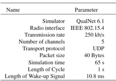
To show the effectiveness of the proposed scheme, we will evaluate its performance using the QualNet 6.1 network simulator and its sensor network modules[28]. Table 2 shows the simulation specifications. The simulation time is set to 65 seconds and each node is equipped with an IEEE 802.15.4 compliant communication module. The transmis- sion rate is set to 250 kb/s. The length of cycle for calcu-
Table 2 Simulation parameters.
Name Parameter
Simulator QualNet 6.1 Radio interface IEEE 802.15.4 Transmission rate 250 kb/s
Number of channels 5
Transport protocol UDP Packet size 40 Bytes
Simulation time 65 s
Length of Cycle 1 s
Length of Wake-up Signal 10.8 ms
lating channel utilization is set to 1 s. The length of wake- up signal is set to 10.8 ms based on “Minimum Length of Wake-up Frame” in[14]. Each node operates in non-beacon mode. The transmission power and the received sensitivity of each node are set so that the communication distance of the data is approximately 250 m. Thus, we assume that the distance that the wake-up receiver can receive the wake-up signal is the same as that of the data in this paper.
We judged that the channel information included in the wake-up signal is negligible in this simulation. The num- ber of available channels of the 920 MHz bands for ROD- SAN node is approximately limited to 15. Furthermore, the channel information can be represented by 4 bits. Since the length step of the wake-up signal is 160μs in citation[14], the length of channel information is 640 μs. From these considerations, the overhead of the introduction for channel information has small impact on the performance.
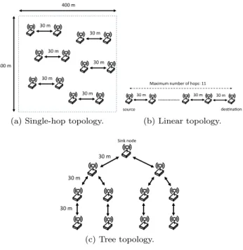
CSMA-CA is run on each node as a MAC protocol, and each transmission is repeated three times according to the IEEE 802.15.4 standard. In this paper, we first evaluate the performance of the proposed scheme separately, and then in a multi-hop network environment whereintra-flow interfer- encecan be expected to occur. Finally, in order to simulate an actual WSAN environment, we evaluate the scheme per- formance in a multi-hop network environment whereinter- flow and intra-flow interferenceoccurs simultaneously. The topologies used in our evaluations are shown below.
First, as indicated in Fig. 6 a, we evaluate the funda- mental performance of the proposed scheme in an environ- ment where there are many sending/receiving nodes pairs engaged in one-to-one communication. In this scenario, we assume that there are many types of one-to-one communi- cation that has a sink node and a sensor node. The distance between the sending and receiving nodes is set at 30 m, and the pairs are placed randomly within a 400 m square. The sending nodes generate a user diagram protocol (UDP) flow to the receiving nodes using a constant bit rate (CBR) from 20 to 50 seconds. The CBR flow packet size is set to 40 Bytes assuming environment sensing, such as a temperature, a humidity, an intensity, and so on. Moreover, the data rate of each sending node is randomly set from 1 to 20 kb/s in order to simulate the temporal change in the utilization con- dition in real environment.
In this scenario, we show the delivery ratio and number of retransmissions necessary when the number of node pairs
Fig. 6 Simulation topoloies.
is changed from 5 to 30. The reason why CBR was selected for use in this simulation is because we anticipate its use in environments where there are enormous numbers of sensors in a limited amount of space, and because it is necessary to simulate an environment in which data flow is constantly generated by those sensors. Accordingly, by setting all send- ing nodes to generate intermittent and continuous flow, we can simulate a high channel utilization environment with a small number of nodes.
Second, we use the linear topology shown Fig. 6 b to evaluate the performance of the proposed scheme in multi- hop networks withintra-flow interference. In this scenario, we assume a linear topology on which infrastructure mon- itoring of bridges and tunnels employs. The distance be- tween each node is 30 m, and each node has a communi- cation route with a neighboring node. Thus, it is an envi- ronment where interference is possible between neighbor- ing and/or distant hops. Assuming real-time monitoring an emergency (the worst case), the sending node generates CBR flow at 10 kb/s to the receiving node located at the op- posite side. In this scenario, we show the change in the de- livery ratio and the channel utilization ratio when the num- ber of hops is changed from 1 to 10.
Finally, we use the tree topology shown in Fig. 6 c to evaluate the performance of the proposed scheme when sub- jected tointra-flow and inter-flow interference. This topol- ogy is designed to simulate actual WSAN operation envi- ronment in which numerous sensors are deployed in wide- area, such as a network for the smart meter, people flow measurement system. As in the previous topologies, the dis- tance between each node is also 30 m, and each node has communication routes with a neighboring node. Here, we have created an environment in which bothintra-flow and inter-flow interference can occur among nodes simultane-
ously. Since the sensor network constructed by the numer- ous numbers of sensors typically forms the tree topology (for example, a network for the smart meters), we assume that all nodes randomly generate CBR flow to the sink node at rates of 1 to 20 kb/s. We then present the delivery ratio, average number of retransmissions, delivery delay, and the channel utilization variations.
The number of available channels is set to five in all scenarios in order to simulate an environment where the channel is congested. Furthermore, the simulation duration is set at 65 seconds, and CBR flows between 15 to 50 sec- onds long are generated. The following three methods are employed as comparative methods by which the sender can specify a channel on-demand:
• ACS: each node selects an ACS scheme (described in Sect. 4.3 and[15]).
• Random: each node selects a channel at random when the node transmits the data frame.
• Fixed: each node continues to use the channel that was randomly selected during the first frame transmission.
Incidentally, we evaluated the Single assuming a conven- tional SANs in which all nodes use one channel. How- ever, its communication performance inevitably results in extreme poor. Thus, we omitted the results of the Single in this paper because there is no obvious performance gap between all methods.
The rate for each CBR flow was set to 1 to 20 kb/s based on a uniform random number. The channel utilization flow of 10 kb/s (expected value for uniform random number) is approximately 0.04 when the transmission rate is 250 kb/s and the packet size is set at 40 bytes. In these scenarios, we assume that the node switches channel when there is one flow of approximately 10 kb/s beyondave ut, and we setα to 0.03.
5.2 Single-hop Topology Performance Evaluation Figure 7 a shows the delivery ratio in the case of a ran- domly generated CBR flow of 1–20 kb/s. The horizontal axis shows the number of communication pairs, and the ver- tical axis shows the delivery ratio, which is the mean of ten repeated simulations. From Fig. 7 a, it can be seen that the OCS scheme achieves a high delivery ratio when compared with the other schemes. The delivery ratios for the OCS and ACS schemes are higher than those for the random and fixed simulations, which means that the OCS scheme can reduce packet losses by reducing packet collisions, even if the number of communication pairs increases significantly.
However, in this simulation, the performance degrades when the number of nodes pairs is 10 or more because the nodes are occupying the channel at a high rate and the number of candidate channels is minimal.
Figure 7 b, which shows the number of retransmissions per node, also provides a strong indicator of channel inter- ference because transmission errors are unlikely to occur when the communication distance between nodes is set to
Fig. 7 Simulation results (single-hop, CBR 1-20 kb/s).
Fig. 8 Impact of parameterα
30 m. That is, frequent packet collisions result from channel interference. It can be seen that both the fixed and random schemes require an increase in the number of the retrans- mission. Additionally, in the fixed scheme, packet colli- sions frequently occur due to the need for continuing to use the same channel, even if it is under a high load, because channel switching is not allowed. In contrast, although the random scheme does allow channel switching, since this scheme selects the new channel randomly, it may select a channel with a high load. Thus, the number of the retrans- missions for both the random and fixed schemes increases significantly.
On the other hand, when compared with the fixed and random schemes, the results show that the OCS and ACS schemes can reduce the number of retransmissions approxi- mately 50%, primarily because packet collisions are reduced by the ability of these schemes to stochastically switch to another channel based on channel utilization values. There- fore, we can conclude that the proposed scheme can improve the delivery ratio by reducing packet collisions in single-hop topology.
Furthermore, we conducted a simulation in the same environment to investigate the impact ofα. In order to keep the channel utilization of each flow constant, the transmis- sion rate of each CBR flow was fixed at 10 kb/s. Figure 8 shows the delivery ratio forα. From this result, when the value ofαwas changed from 0.03 to 0.15, the performance gap in terms of delivery rate was approximately 1%. So, we judged that impact ofαis enough small in our proposed scheme. Therefore, we setαto 0.03 in the following simu- lations.
5.3 Linear Topology Performance Evaluation
Figure 9 shows the delivery ratio for each scheme in Fig. 6 b.
Fig. 9 Delivery ratio (Linear).
Fig. 10 Channel utilization ratio (Linear).
Here, the horizontal axis shows the number of hops and the vertical axis shows the delivery ratio, which is the mean value of 10 repeat simulations. As can be seen in this figure, the fixed scheme drastically reduces the delivery ratio as the number of hops increases because the fixed scheme node is unable to change channels even if packet collisions due to intra-flow interferenceoccurs frequently. On the other hand, the other schemes achieve delivery ratios that exceed 99% due to their ability to switch channels and thereby re- duce packet losses by avoiding concentrating on a specific channel.
Figure 10 a–10 d shows the channel utilization ratios for each scheme. In these figures, the horizontal axis shows the simulation time, and the vertical axis shows the chan- nel utilization ratio when the number of hops is ten. As shown in Fig. 10 a and 10 b, the channel utilization ratios for all nodes converge by using the channels equally. Further- more, while the random scheme in Fig. 10 c also allows the channels to be used equally, the scheme results in frequent channel shifts. Taken together, these results indicate that schemes that permit channel switching show relatively sta- ble performance in scenarios with a small amount of flows.
Next, looking at schemes that cannot use channels equally, Figure 10 d shows that channel utilization tends to concentrate on a specific channel because the fixed scheme
Fig. 11 Simulation result (Tree).
does not permit each node to switch channels. Therefore, the packet loss factor shown in Fig. 9 is the result of con- centration on a specific channel, which is especially severe when the number of hops is large. Therefore, even if there are only a small number of nodes, our results confirm that the ability to switch channels is critical to reducing packet loss and improving performance levels.
5.4 Tree Topology Performance Evaluation
Figure 11 shows the delivery ratio, the number of retrans- missions, and delivery delay for each scheme in the tree topology.
First, we show that delivery ratio for the fixed scheme has decreased to 84% from Fig. 11 a, and that the number of retransmissions and delivery delay for the fixed scheme is larger than any other tested methods. From these re- sults, we can deduce that packet collisions occur frequently and CSMA-CA retransmission processing is performed fre- quently. Furthermore, there is a difference in the utilization of each channel in Fig. 12 d, which indicates that in spite of the increasing utilization of Channels 3 and 4, Chan- nels 2 and 5 are not being used significantly. As a result, a node that uses Channels 3 and 4 suffers frequent packet collisions, multiple packet losses, and an increase in trans- mission delays. Second, the delivery ratio for the random scheme is approximately 93%. However, even though the random scheme delivery delay is the lowest of all the tested schemes, the number of retransmissions is as high as that for the fixed scheme. This indicates that packet collisions occur frequently because the scheme randomly selects chan- nels, thereby making it inevitable that high utilization chan- nels will sometimes be selected. Nevertheless, the random scheme shows that performance levels can be maintained by the utilization of retransmission processing. In a case
Fig. 12 Channel utilization ratio (Tree).
involving a communication method with a poor retransmis- sion function, the random scheme may not be effective for a WSAN. On the other hand, from Fig. 12 c, it can be seen that the utilization of each channel can be accomplished on average.
Third, the delivery ratio for the ACS method is approxi- mately 90%, which is second lowest, but higher than that for the fixed scheme. Focusing on Fig. 12 b, it can be seen that the utilization rates for each channel are very variable. This means that this scheme cannot be adapted to flows with dif- ferent transmission rates because channel switching is ran- domly determined by selecting from one with a smaller av- erage utilization from all the available channels. As a re- sult, packet collisions can be expected to occur frequently.
Nevertheless, when compared with the random and fixed schemes, it can be seen that the ACS scheme is capable of reducing the number of retransmissions because it attempts to use all channels equally.
Finally, as shown in Fig. 11 a, the OCS scheme can achieve a delivery ratio of approximately 98%. Further- more, the number of retransmissions is the lowest of all the schemes examined, and the delivery delay can be kept to within 0.4 seconds. From these results, we can deduce that even though packet collisions sometimes occur at var- ious nodes with high loads that have not switched chan- nels, the OCS scheme is definitely better at suppressing such collisions than the other methods tested. Furthermore, in Fig. 12 a we can see that the OCS scheme can equalize chan- nel usage and that nodes using high load channels can easily switch to low load channels. When the simulation time is 20 seconds, we can see that some nodes switch from Chan- nel 5 to Channel 4, and that utilization of all channels con- verges to equal levels when the simulation time is 25 sec- onds. Based on these results, it is clear that the proposed OCS scheme can use channel resources effectively, reliably, and equitably, even in different environment.
All simulation results show that the OCS scheme in
ROD-SANs achieves equal utilization of channel resource compared to conventional schemes included ACS schemes.
Also, the OCS scheme can not only avoid packet collisions and but also achieve high delivery ratios by using the wake- up receiver and the wake-up signal efficiently.
6. Conclusion
In this paper, we began by explaining how ROD-SAN tech- nology simultaneously achieves power saving and a high response performance. However, we also showed that load concentrations on a single channel causes performance degradation due to frequent packet losses, together with in- crease in the number of retransmissions and the transmis- sion delay. Therefore, in order to achieve both power saving and a high response performance, we proposed a modifica- tion of previously reported ACS scheme. While the original ACS scheme was designed to reduce packet collisions by using all available channels equally, it resulted in a prob- lem whereby the load on at least one of the channels would remain high. Therefore, in this paper, we have proposed and improved version of the ACS scheme, referred to as the OCS scheme. In simulation testing, the results show that the newly proposed scheme can use channel resource effec- tively, reliably, and equitably, even in different environment, such as in the presence of different topologies or data rates.
Acknowledgments
The authors would like to thank Mr. T. Hidaka for his great technical assistance with the experiments. Furthermore, this work supported in part by JSPS KAKENHI of Grant-in-Aid for Scientific Research (C) (No. 16K00131).
References
[1] F. Rahimi and A. Ipakchi, “Demand response as a market resource under the smart grid paradigm,” IEEE Trans. Smart Grid, vol.1, no.1, pp.82–88, 2010.
[2] K. Pister, et al., “TSMP: Time synchronized mesh protocol,”
IASTED Distributed Sensor Networks, pp.391–398, 2008.
[3] M. Buettner, G.V. Yee, E. Anderson, and R. Han, “X-MAC: a short preamble MAC protocol for duty-cycled wireless sensor networks,”
Proceedings of the 4th international conference on Embedded net- worked sensor systems, ACM, pp.307–320, 2006.
[4] P. Dutta, S. Dawson-Haggerty, Y. Chen, C.-J.M. Liang, and A.
Terzis, “Design and evaluation of a versatile and efficient re- ceiver-initiated link layer for low-power wireless,” Proceedings of the 8th ACM Conference on Embedded Networked Sensor Systems, ACM, pp.1–14, 2010.
[5] IEEE 802.15 WPANTM Task Group 4 (TG4), http://www.ieee802.
org/15/pub/TG4.html
[6] I.F. Akyildiz, T. Melodia, and K.R. Chowdhury, “A survey on wire- less multimedia sensor networks,” Computer networks, vol.51, no.4, pp.921–960, 2007.
[7] J. Yick, B. Mukherjee, and D. Ghosal, “Wireless sensor network survey,” Computer networks, vol.52, no.12, pp.2292–2330, 2008.
[8] M.A. Yigitel, O.D. Incel, and C. Ersoy, “QoS-aware MAC proto- cols for wireless sensor networks: A survey,” Computer Networks, vol.55, no.8, pp.1982–2004, 2011.
[9] O.D. Incel, “A survey on multi-channel communication in
wireless sensor networks,” Computer Networks, vol.55, no.13, pp.3081–3099, 2011.
[10] M.D. Jovanovic and G.L. Djordjevic, “Tfmac: Multi-channel mac protocol for wireless sensor networks,” Telecommunications in Modern Satellite, Cable and Broadcasting Services, 2007, TELSIKS 2007, 8th International Conference on, IEEE, 2007.
[11] O.D. Incel, L. van Hoesel, P. Jansen, and P. Havinga, “MC-LMAC:
A multi-channel MAC protocol for wireless sensor networks,” Ad Hoc Networks, vol.9, no.1, pp.73–94, 2011.
[12] T. Nagayama, et al., “Reliable multi-hop communication for struc- tural health monitoring,” Smart Structures and Systems 6.5-6, pp.481–504, 2010.
[13] S. Tang, H. Yomo, Y. Kondo, and S. Obana, “Wake-up receiver for radio-on-demand wireless LANs,” EURASIP Journal on Wireless Commun. and Networking, vol.2012, no.1, pp.1–13, 2012.
[14] H. Yomo, T. Kawamoto, K. Abe, Y. Ezure, T. Ito, A. Hasegawa, and T. Ikenaga, “ROD-SAN: Energy-Efficient and High-Response Wireless Sensor and Actuator Networks Employing Wake-Up Re- ceiver,” IEICE Trans. Commun., vol.E99-B, no.9, pp.1998–2008, Sept. 2016.
[15] T. Hidaka, D. Nobayashi, Y. Fukuda, K. Tsukamoto, and T. Ikenaga,
“Transmission Channel Switching Based on Channel Utilization in ROD-SAN,” Future Network Systems and Security, Springer Inter- national Publishing, pp.129–138, 2015.
[16] T. Hidaka, D. Nobayashi, Y. Fukuda, K. Tsukamoto, and T.
Ikenaga, “Performance evaluation of multi-hop communication with a dynamic channel switching scheme in ROD-SAN,” IEEE Pacific Rim Conference on Communications, Computers and Signal Pro- cessing, 2015.
[17] T. Tani and H. Yomo, “Wake-up Frame Detection using Correlated Received Signal Strength for On-Demand WiFi Wake-up,” Proc. of IEEE International Conference on Communication Systems (ICCS), 2014.
[18] F.Z. Djiroun and D. Djenouri, “MAC Protocols With Wake-Up Ra- dio for Wireless Sensor Networks: A Review,” IEEE Communica- tions Survey & Tutorials, vol.19, no.1, pp.587–618, 2017.
[19] J. Chen, Q. Yu, B. Chai, Y. Sun, Y. Fan, and X.S. Shen, “Dynamic Channel Assignment for Wireless Sensor Networks: A Regret Matching based Approach,” IEEE Trans. Parallel Distrib. Syst., vol.26, no.1, pp.95–106, 2015.
[20] X.-C. Hao, X.-Y. Ru, X.-D. Li, and M.-J. Xin, “Energy Efficient Based Channel Assignment Game Algorithm for Wireless Sen- sor Network,” Wireless Personal Communications, vol.85, no.4, pp.2749–2771, Springer, 2015,
[21] R. Soua and P. Minet, “Multichannel Assignment Protocols in Wire- less Sensor Networks: A Comprehensive Survey,” Pervasive and Mobile Computing, Elsevier, vol.16, pp.2–21, 2015.
[22] X. Wang, X. Wang, X. Fu, G. Xing, and N. Jha, “Flow-Based Real- Time Communication in Multi-Channel Wireless SensorNetworks,”
Proc. of EWSN 2009, vol.5432, pp.33–52, 2009.
[23] R. Soua, P. Minet, and E. Livolant, “MODESA: an optimized multi- channel slot assignment for raw data convergecast in wireless sensor networks,” Proc. of IPCCC, 2012.
[24] K.-H. Phung, B. Lemmens, M. Goossens, A. Nowe, L. Tran, and K.
Steenhaut, “Schedule-based multi-channel communication in wire- less sensor networks: A complete design and performance evalua- tion,” Ad Hoc Networks, vol.26, pp.88–102, Elsevier, 2015.
[25] Q. Yu, J. Chen, Y. Fan, X. Shen, and Y. Sun, “Multi-Channel Assign- ment in Wireless Sensor Networks: A Game Theoretic Approach,”
Proc. of IEEE INFOCOM 2010, pp.1–9, 2010.
[26] A. Saifullah, Y. Xu, C. Lu, and Y. Chen, “Distirbuted channel allo- cation protocols for wireless sensor networks,” IEEE Trans. Parallel Distrib. Syst., vol.25, no.9, pp.2264–2274, 2014.
[27] Y. Wu, K.S. Liu, J.A. Stankovic, T. He, and S. Lin, “Efficient Multichannel Communications in Wireless Sensor Networks,” ACM Transactions on Sensor Networks, vol.12, no.1, March 2016.
[28] QualNet 6.1, http://www.scalable-networks.com
Daiki Nobayashi received the B.E., M.E.
and D.E. degrees from Kyushu Institute of Tech- nology, Tobata, Japan in 2006, 2008, and 2011, respectively. From April 2010 to March 2012, he was a Japan Society for the Promotion of Science (JSPS) Research Fellow. Since March 2012, he has been an Assistant Professor in Department of Electrical and Electronic Engi- neering, Faculty of Engineering, Kyushu Insti- tute of Technology. His research interests in- clude network architectures and protocols, wire- less LANs, multi-hop wireless networks, wireless sensor and actuator net- works. He is a member of IEEE and IEICE.
Yutaka Fukuda received B.E., M.E. and D.E. degrees in computer science from Kyushu Institute of Technology, Iizuka, Japan in 2000, 2002 and 2005 respectively. From 2003 to 2007, he was a Research Associate in the Informa- tion Science Center, Kyushu Institute of Tech- nology. Since April 2007, he has been an Assis- tant Professor in the Information Science Cen- ter, Kyushu Institute of Technology. His re- search interests include performance evaluation of computer networks, wireless networks, and transport protocol. He is a member of the IEEE and IEICE.
Kazuya Tsukamoto received the DE de- gree in computer science from the Kyushu Insti- tute of Technology (KIT), Japan, in 2006. From April2006 to March 2007, he was a Japan So- ciety for the Promotion of Science (JSPS) re- search fellow at KIT. In 2007, he was an assis- tant professor in the Department of Computer Science and Electronics, KIT, and then has been an associate professor in the same department since April 2013. His research interests include performance evaluation of computer networks and wireless networks. He is a member of the ACM, the IPSJ, the IEICE, and the IEEE.
Takeshi Ikenaga received B.E., M.E. and D.E. degrees in computer science from Kyushu Institute of Technology, Iizuka, Japan in 1992, 1994 and 2003, respectively. From 1994 to 1996, he worked at NEC Corporation. From 1996 to 1999, he was an Assistant Professor in the Information Science Center, Nagasaki Uni- versity. From 1999 to 2004, he was an Assistant Professor in the Department of Computer Sci- ence and Electronics, Faculty of Computer Sci- ence and Systems Engineering, Kyushu Institute of Technology. Since March 2004, he has been an Associate Professor in the Department of Electrical, Electronic and Computer Engineering, Fac- ulty of Engineering, Kyushu Institute of Technology. His research interests include performance evaluation of computer networks and QoS routing. He is a member of IEEE and IEICE.