[Reports of the Faculty of Engineering at Yamanashi University, No.44,1993.12]
Original Paper
Design of Adaptive Beam Filters
(Received on 31, August 1993)
MakotoOHKI YasukazuMANO
TomonoriHIRASHIMA SumihisaHASHIGUCHI
Abstract
This paper proposes a design rnethod of beam filters with independent setting margins in direction and velocity. The proposed method is based on the transformation of one−dimensional analog transfer functions and can be easily modified to construct the adaptive beam filter byupdating the transformation coefficients. This paper also shows simulation results of the
adaptive beam filter designed by the proposed method. The direction and the velocity of a plane wave can be changed by some reason such as the density change of the medium. In order to follow the change, the adaptive beam filter is n㏄ded. This paper proposes a construc− tion method of adaptive beam filters and shows simula. tion results of the adaptive beam filter.1
IntI・oduction
Multi−dimensiona1(m−D)digital signal processing plays important roles in such apPlications as medical im− age processing, moving picture processing, robotics and seismic signal processing. In seismic signal processing and radar or sonar signal processing, three−dimensional (3−D)signals, which have two spatial parameters and atemporal parameter, are processed. Especially, plane waves are important for those apPlication areas. In or− der to extract a plane wave among other plane waves and noise, the beam.filter is used[1]. Bruton et al. proposed a design lnethod of beam丘1− ters on the analog domain[2]. Although the method can easily design beam filtets, it can not specify mar− gins in propagation direction and in velocity of a plane wave independently. In this paper, a method, which can specify margins in direction and velocity of a plane wave independently, are proposed. ’Department of Electrical Engineering and Computer Science,Ya− manashi University †Fuji Color Service Co.,Ltd. ‡Meidensha Co.,Ltd.2
Plane wave signals
In the apPlication such as seismic signal processing, signals are observed by the sensor array located on the earth and are represented by the s(x,y,t)where x and yare spatial parameters and t are a temporal parame− ter. When the sensor array is su伍ciently apart from the origin of earthquake, the seismic wave can be regarded to as a plane wave. The plane wave is represented as follOWS; s(x,y,t)=f(diX+d2y 一(dl+dl)t) (1) where f(・)is a function which represents the wave form, dl and d2 are the component of the motion vector dニ (dl,d2). The propagation direction of the plane wave is d d 確十d3, 婿十d3 the plane wave is d…十d日. The spec七rum of a plane wave signal s(x,y,t)is ob. tained by performing the Fourier transform of s(x,y,t); ( )and・th・p・・p・g・ti・nv・1・・ity・f5(ピ1,ω2,ω3) =工工∫:・(・,y,・)・・xp{−」(・1・+・・Y+・・t)}d・d・dt 一工∠:∫:∫(…+・・y−(d?+d;)・)・ exp{一ゴ(ωlx十ω2Y十ω3t)}dx(ly(況 =ピ∠:・xp{一ゴ・・(d・・+d・y)/(dl+d;)}F←晶日) ・exp{−」(ω1¢+ω2Y)}dxdy =F( W3п`+d萎)ピ・xp{一ゴ(・1+・誌萎)鋤 工・xp{一ゴ(・・+・・ai,¢kEi:+2d:)・}吻
=F
b副・( dlω’+ω3d…+d;)・(・・+・・轟1)・) whereωl andω2 are spatial frequencies along x and y direction respectively,ω3 is the temporal frequency,δ(・) represents the Dirac,s delta function, and F(・)are the Fourier transform of the wave form function∫(・); F(ω)一∠ン(り・xp(一μ)∂£・ (3) From eq.(2), the spectrum of a plane wave can exist when the following conditions are held; ω・+ω・嶋黶E
ω・+ω・ナ一・・
(4) Consequently the spectrum distributes on a line which passes through the origin of the three−dimensional (3−D)frequency space and parallels to the vector (−d1,−d2,d;十d;)(the propagation direction vector)・ passband of the beam丘lterω3
In the processing of plane waves, extracting a plane wave among other plane waves and noises is important. This operation can be performed by the beam丘lter whose passband lies only on a line in the 3−D frequency space・ 3.13
Design of beam mters
Bruton et al, ters using resonant planes[2】. The method constructs a beam丘lter by intersecting two 3−D analog filters whose Pεtssbands are planes passing through the origin of the 3−Dfrequency space(see Fig.3.1). 1、et Tl(s)and T2(s)be transfer functions of 1−D ana− log lowpass filters. The transfer function of 1−D analog 丘lters can be easily obtained from various design tables. 3−Danalog filter T{(sl,52,53)and T5(sl,s2,83)can be obtained by transforming Tl(3)and 2)(5)as follows; T{(S、,S2,S3)=T、(8) α151十α232十α333 (5) 8= 1α1Design of beam filters using reso−
nant planes
proposed a design method of beam丘1一 T5(・、,・2,・3)= T・(s) β181+β2S2+β3S35=
1β1 (6) Figure 1:Intersection of two resonant planes.ω2
ω1 whereα1,α2,α3,β1,β2,β3≧0,1α1= α1十α日十α§, and lβ1= β∼十β日十β3. Let the passbands of T,(s) and T2(s)be O≦ω≦ωpl and O≦ω≦ωp2, resp6c− tively. Then the passbands of T{and Ti are slices which have widths 2ωpl and 2ωp2 and surround the following planes; α1ω1十α2ω2十α3ω3=0 (7) β・ω・+β2ω・+β3ω3=0. (8) Bruton et aL call these planes the rεsonant plane[2】. 3−Dbeam filter T’(sl,s2,s3)in the analog domain can be obtained by the series connection of T{and T6; T’(・・,・・,・・)=TI(・・,・2,S,)・昭(・、,・、,・,). (9) A3−D beam filter H(zl,z2,z3)in the digital domain can be obtained by the bi−linear z−transform of T’; Consequently,Zi−1
3i= Zi十1 , i=1,2,3. H’i・・,Z・,Z・)=H{(Z、,・Z2,Z3)・Hl(Z、,・、,・、) (10) (11)ω3
ω;(vel・city ω{(direω2
ti・n)propagation
vector 2’D plana・ filt・rs TI(s・,s2) /レ 老 ma.rgin in VelOCityW3
beam
Wl
=−Dplana・租t・・
卜 Ti(S・,32,33) //1 .L(/ margm in direction ω1 Figure 4:Beam丘lter by the improved method. Figure 2:Aplane intersecting orthogonally the propa. さ gatlon vector・ ω1 crOSSE←・f
ectb
ectionbeam
ω{◎ve
1mp「ove ωs crOSS S ■モ狽撃盾 ar ? in in of aE畑口/
eam
一’m
rgin in directi n , @ ω1 input 孟 2.D filterF
M
2 3−D filter contoroller of frame memoriesF
M
3output
FM:frame memory
Figure 5:Inversion of the direction of signals. Figure 3:Margins in direction and velocity. where∬{(zl,z2,z3)is the bi−linear z−transform of T{(sl,s2,s3) and ll5(zl,z2,z3) is the bi−linear z_ transform of the昭(sl,82,s3). If 1−D analog lowpass filter Tl(8)and T2(s)arebounded−input bounded−output(BIBO)stable andα1,
α2,α3,β1,β2,β3≧0,then the 3−D digital transfer func− tion∬{(2Zl,2膓2,2!3)and H6(z1,z2,z3)are practical−BIBO’ stable [3]and therefore H(zl,z2,z3) is also practical− BIBO stable[2|. 3.2Let
Design method with independent
setting of marginsin direction and
velocity
consider a plane(ω1,ω〉)which intersects the propagation direction vector d orthogonally(see Fig.2). In this plane, theω{−axis corresponds the propagation direction of the plane wave and theω;−axis corresponds the velocity of the plane wave. As Bruton et al. use two 3−D planar filters to obtain a 3−D beam filter, αi,β‘(i= 1,… 3)are larger than O in fact. Conse− quently, the Bruton,s method can not specify margins in direction and velocity independently because a res− onant plane can not intersect another resonant plane orthogonally in the Bruton’s method and so the cross section of the passband of the beam filter is a rhombus [4]. Hirashima proposed a improved design method which can specify margins in direction and velocity l4]. In the method, a 2−D filter and a 3−D丘lter instead of two 3−D filters are connected in series. The 2−D丘lter T{(sl,s2) has the passband surrounding the plane; α1ω1+α2ω2=0 (12) and dominates the margin in direction. The 3−D filter T5(81,s2,s3)has passband surrounding the plane; β1ω、+β2ω2+β3ω3=0 (13) .and dominates the margin in velocity(see Fig.4). As Bruton,s method, TI(81,82)and Tl(81,82,s3)are ob− tained from a 1−D prototype丘lter Tl(8)and T2(s)by the transformation. Discrete versions H{(Zl,z2)and H5(Zl,Z2,Z3)of TI and Ts are obtained by the bi−linear z−transform. H{(Z1,X2)and∬≦(z1,z2,z3)are practical−BIBO stable ifα1,α2,β1,β2,β3≧0. Whenα1,α2,β1,β2,禽≧ 0,the direction of beam filter can not varies in whole direction. In order to obtain the beam丘lter with an arbitrary direction, the direction of signals has to be inverted by the line−and/or frame−memory as shown in Fig.5.ノ ω2 π 0 一π
◎
0 (a)0.2∼鷹π ’ 1 t ω2 π 0 一Pt ・◎・・ 0 (b)0.5∼/5π ’ 1 t ω2 π 0 一π 、 0 (c)0.9∨「3π ’ 1 Figure 6:Contour−line maps of a beam filter. (n−1)−th frame motion vector plane wa じ contact point n−th frame search⇒△・
3.3 Figure 7 Detection of the motion vector.Design example
△r An design example of beam丘lters is showed. In the example, the 1−D analog prototype filter is the following butterworth lowpass filter; 1 Ti(s)= (riS十1)・(r子32十〇.618034ris十1) 1 ・ (r∼32十1.61803riS十1) (14) where i=1,2, ri=1/ωi, andωi is the cutoff fre− quencies. Figure 6 shows the contour−line maps of the magnitude response of the beam filter with a propaga− tion direction vector(0.5,0.5,0.5). Figure 6(a)is the contour−line map on the plane which intersects the beam orthogonally and lies O.2・v/5πapart from the origin. .Similarly, Fig.6(b)shows the contour−line map on the plane which lies O.5・ V宮π apart from the origin, and Fig.6 (c)shows the contour−line map on the plane which lies O.9・v/5πapart from the origin,4
Adaptive beam mters
The beam filters designed by the proposed method can be eaSily modified to obtain an adaptive beam丘lter by updating the transformation coe伍cientsα1,α2,β1, ノ β2andβ3. In order to update the transformation co− efHcients, the detection method of the motion vector is needed. In tllis paper, the wave fbrm function∫(・)of a plane wave is assumed to be a pulse function with nar− row width. Therefore the plane wave becomes a moving line on the x−y plane. This section describes a simple detection method of the motion vector for the moving line on the x−y plane[5]. Let find the motion vector at n−th frame. At first, the proposed algorithm伽d intersection points between the moving line and axes on(n−1)−th frame. Then the algo− rithm searches intersection points on n−th frame starting from the intersection points on(n−1)−th frame. Let△x be the distance betw㏄n the intersection point of the x− axis on n一七h frame and that on(n−1)−th frame and let △ybe the distance between the intersection point of the y−axis on n−th frame and that on(n−1)−th frame. The motion vector(d,,d2)can be calculated by the following equations; ∂・塩・i・・ i _1△ytan △x) d・−Ax・i・itan−・念)・…(・・n−・念)・ (15) (16) If the motion vector(d1,d2)is obtained, then the transformation coef丘cients can be calculated by the fol− lOWing eqUaもiOnS; α1 α2 β1 β2 β3 ld,1/ d?十d; ld,1/ d…十d3 1di 1/ d{十d茎十1 ld21/ di十d;十1 (17) (18) (19) 1/ d?十d3十1. (20) (21)Figure 9:Input signal at 80th and 120th frame. Figure 10:0utput signal at 80th and 120th frame. input 2.D filter detection of motion vector
F
M
2 3−D filter updating mter coeMcients colltroller of frame memoriesF
M
3output
Figure 8:Adaptive beam filter system. Figure 8 shows the system configuration of the proposed adaptive beam丘lter.5
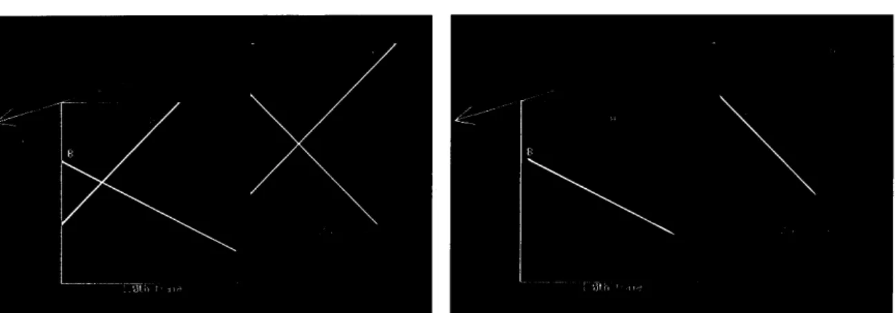
Simulation results
Consider the situation that there are a plane wave with the constant motion vector and a plane wave with the variable motion vector. The goal of this simulation is the extraction of the plane wave with the variable motion vector. The input signal used in this simulation has 256 columns along x−direction,2561ines along y− direction and 160 frames along t−direction. The motion vectors are specified as follows; plane wave A:(−0.5,0.5)(constant) plane wave B:(1.0,0.5)by 40th frame (0.5,0.5)from 41th frame to 80th frame (0.5,1.0)from 81th frame. The Wave form function f(p)used in the simulation is a gaussian f皿ction as follows; f(P)=255・xp{−O.2P2}. (22) The cha.racteristics of the beam filter used in the simu− lation are specified as follows; filter order :bandwidth :
(margin) 5th for x−, y−and君一directionま認::蕊:㌻
Figures 9 and 10 show 80th and 120th frame of the input and the output images. In those figures, the up− ward line to the right is the plane wave A and the upward line to the left is the plane wave B. The plane wave A moves to the upper left direction and the plane wave B moves to the upper right direction. The plane wave A is eliminated by the beam filter and the plane wave B is extracted. This processing needed about three min− utes per one frame on an engineering workstation(Sun Sparc−Station IPC). The parallel processing technique will be needed for the real time processing.6
Conclusions
Asimple design method of beam丘lters with indepen− dent setting margins in direction and velocity is pro. posed. The proposed method is based on the trans− formation of 1−D analog transfer functions and can be easily modified to construct the adaptive beam filter by updating the transformation coef五cients. Simulation re. sults of the adaptive beam filter designed by the pro− posed method are showed.1) 2)