Hands-free Speech Recognition Based on 3-D Viterbi Search Using a Microphone Array
4
0
0
全文
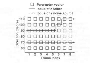
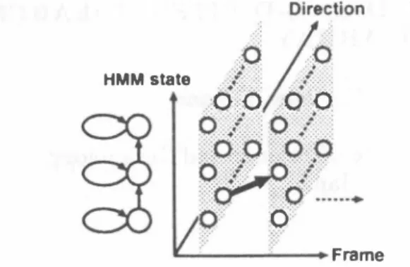
(2) ーー一. , kHz " 一.2 kHz ----- 4 kHz --6kHz. 。/0 <. }?>:: /.<f:.: OV0 0 0 .. HMM state. ヨloTW. I ::00:: 0::0. 10許認 訴 I t � i:O…→ iノo. 0. Fra町、e Dlr舵t刷、[d・gr..). Figure 2: Viterbi search in 3・dimensional trellis space com. posed of talker directions, input frames, and HMM states.. Figure 3: Directive gain pattern calculated for 6 kHz band limited white Gaussian noise.. recognition a1gorithm based on 3・D Viterbi search which. considers multiple talker direction hypotheses simultane. ously.. as follows:. The standard HMM・based speech recognizers ob. serve the frame sequence of the pむameter vectors, then. perform Viterbi search on trellis plane composed of input fr辺国S姐d HMM states. The proposed a1gorithm is an ex. ω(d,n). tension of this 2-D Viterbi search. It observes the direction. frame sequence of the pむameter vectors, then performs. Viterbi search in 3-dimensional trellis space composed of. talker directions, input frames, and HMM.states as shown. in Figure 2. As a result, a locus of the talker and a phoneme sequence of the speech are obtained by finding an optimal path with the highest likelih∞d. The likelihood is calcu. lated as follows: α (q,d,n). =. 玄 ) ←(ア = 1喝18;' 三: 乞. {c(djn')}μ (3) {c(d'jn')}μ. where c(djπ) is the maximum value of cepstrum coe侃cients in high quefrency region, which is extracted by cepstrum. analysis for the direction d and the frame index n . This value becomes larger when the pitch harmonics exist. μ is the parameter to control the weight effect叩d. =. parameter to adjust the continuation.. loga(q' ,q) 1 , ��{α(q' ,d' n- )+ +loga(d' ,d)}+ logb(q ,x(d,n)),. (1 ). where d is the direction, n is the frame index, and q is the HMM state index.α(q' , q) is the transition probability from. 3. 3.1.. Experiment Conditions. A speech recognizer is based on the tied-mixture HMM with. 256 distributions.. talker moves.. and another 216 words are used for testing.. It can be assumed that the talker moves. to neighboring directions at most, since a duration of the. frame in speech recognition is about 10 msec. Therefore it is reasonable to restrict the range of movements as follows:. a(d',d) =. � ネ l. 0. , ,. Id- d'l壬ムd. ld-d'I>ßd. ,. (2). As mentioned above, the proposed algorithm五nds an. optimal path with the highest likelihood. Therefore, when the likelihood in the correct talker direction is lower than. that in the other ones, the performance of the proposed algorithm is degraded.. ln such a case, it will be effective. to raise the likelih∞d in directions with speech-like char. acteristics. The pitch harmonics of speech can be used 出. a me出ure of speech-like characteristics. ln this paper, an. weight function based on the pitch harmonics is introduced. 246. 92. A speech corpus is the ATR Japanese. speech database Set-A. 2620 words of the speaker MHT むE. used for training 54 context independent phoneme models Speech sig. nals are sampled at 12 kHz and windowed by the 32 msec Hamming window every 8 msec.. Then 16-order mel fre. quency cepstrum coefficients (MFCCs), 16-order ßMFCCs, and a ßpower are calculated. A microphone array is a lin. ear and equally spaced array composed of 14 microphones,. where the distance between two adjacent microphones is 2.83 cm. As the microphone array signal processing, the delay-and-sum beamformer is used.. where 企d is the range of movements. is the. EXPERIMENTS AND RESULTS. the HMM state q' to q,a(d' , d) is the transition probability from the direction d' to d, and b is the output probability. The transition probability α(d' ,d) represents how likely the. 11. The directional gain. pattern calculated for 6 kHz band-limited white Gaussian. noise is shown in Figure 3. The direction-frame sequence of the p訂ameter vectors is computed every 10 degree. 3.2.. Simulated data experiments. We consider two arrangements of the sound sources and the. microphone array as shown in Figure 4.. (1) The positions of the talker and the noise source are fixed..
(3) Table 1: Word recognition accuracy (WA) [%] and talker locaiization accuracy (TLA) [%] for the fixed talker on the simulated dat 品 . Clean SNR 20 dB SNR 10 dB WA Single microphone. 3-D Viterbi search 2. (ð.d = (ムd =. WA. TLA. TLA. WA. 80.0. 25.9. 96.2. 100.0. 94.9. 100.0. 90.7. 10). 96.2. 99.0. 72.6. 40.9. 28.2. 17.9. 10,μ= 40,1/ = 20). 96.2. 99.1. 94.9. 77.6. 88.4. 71.2. Delay-and-sum beamformer 3-D Viterbi search 1. TLA. 96.2. 100.0. Table 2: Word recognition accuracy (WA) [%] and talker locaiization accuracy (TLA) [%] for the moving taiker on the simula.ted da.ta. Clean WA Single microphone. 3-D Viterbi search 2. (ð.d = (ムd =. 91.6. 100.0. 86.5. 86.7. 74.5. 44.7. 26.8. 21.0. 10,μ= 40,1/ = 10). 96.7. 84.0. 93.9. 63.1. 84.7. 51.9. White Gaussian. 一一- 3いo Vlt町bl伺arch 2 3いo Vlterbl帥arch 1 ー._. Corn蛇t IOCU8 01 the talker. 180 I 1// 160 1/〆〆 140 g120 Z1∞ 80 1 / I 60 烹 � \./ ‘ 三40�! \1 \/ .,・ 1; ;; Jt.� o ; ー.........:,'\11 ;-;: 20 � ./〆 Ul 0020 40 60 80 1001120 140 160. 。. D Talker. I---Ìl1 Ta 蜘. 101 (1). (2). 100.0. 100.0. 96.2. nOI$・sourc・. ー→. TLA. 22.2. 95.8. White Gaussian. 。|. WA. TLA. 10). nOl8・sourc・. iOI .� 1 .140/. SNR 10 dB. SNR 20 dB WA 79.6. 95.8. Delay-and-sum beamformer 3-D Viterbi search 1. TLA. /.. 180. r:: o. Figure 4・Arrangement of the sound sources a.nd the micro. �. phone arra.y. (1) The positions of the taiker and the noise source are fixed. (2) The taiker moves from 0 degree to 180 degree while uttering each word. The position of'the noise source is fì.xed.. r. :�. r". Frame Index. Word beglnlng. (2) The taiker moves from 0 degree to 180 degree while. Word end. Figure 5: Exa.mple of the locus of the talker obtained by. uttering each word. The position of the noise source. 3-D Viterbi search 1 a.nd 2 for the moving ta.lker in SNR 20. is fì.xed.. dB. The outputs of ea.ch microphoneむe simulated considering only time difference of the wa.vefront arriva.l without rever berations.. of frames tha.t the correct talker direction is selected within. Word recognition a.ccuracy (WA) and talker locaiization. 5 degree di仔erence.. accura.cy (TLA) for the fì.xed talker a.re shown in Ta.ble 1.. These results are summarized a.s follows:. The TLA is defìned a.s follows: TLA =. "u",v�.r �. .��..��. .:-;.._�. number of correct frames number of total speech frames. • x. 100[%],. (4). talker direction compared with that of the single mi crophone.. where the number of correct frames is the number of frames. •. that the correct taiker direction is selected. In Ta.ble 1, the. The WA of the 3-D Viterbi sea.rch 2 is almost equal to tha.t of the dela.y-a.nd-sum bea.mformer, while the. delay-and-sum bea.mformer indicates tha.t the correct talker. WA of the 3-D Viterbi sea.rch 1 is degra.ded due to. direction is known. The frame sequence of the para.meter. low TLA. vectors is obtained by steering the beamform only to the correct talker direction.. The WA of the delay-and-sum beamformer is im proved by steering the bea.mform only to the correct. An example of the locus of the talker obtained by the 3-D. The 3-D Viterbi search 1 indi. cates that Viterbi search in 3-dimensional trellis spa.ce is. Viterbi search 1 and 2 for the moving talker in SNR 20 dB. performed without the weight function.. The 3-D Viterbi. is shown in Figure 5, where the horizontal axis is the frame. search 2 indica.tes that the pitch harmonics weight function. index and the vertical axis is the direction. The locus of. is used.. the talker obtained by the 3-D Viterbi search 1 is degraded,. The WA and TLA for the moving taiker are shown in. because the likelihood in the correct talker direction is lower. Table 2. In Table 2, the TLA is defì.ned based on the number. tha.n that in the other ones. The 3-D Viterbi search 2 works. 247 93.
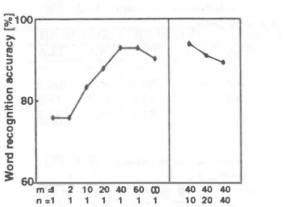
(4) iF1∞ 〉‘ u 帽 ‘・ 3 u. \、. 8. Single microphone. 3-D Viterbi search 2. z. 80 室 c. (ムd = 10, μ = 80,11 = 10). c:n o. s 0. Figure 6:. 52.3. speakers are used instead of the talker and the noise source.. 芝. 3:60. 10. 38.4. 町、� n =1. 2 10 20ω60∞ 1 1 1 1 1 1. The loud speakers face the microphone array. The cepstrum. mean normalization technique is also applied to the speech. 4040 40. 10 20・0. recognizer described in section 3.1.. The word recognition accuracy is shown in Table 3. In. Word recognition accuracy obtained by 3-D. Table 3, the SNRs are calculated using the power values. Viterbi search 2 in SNR 20 dB for several combinations. at the positions of the sound sources. Therefore the SNRs. of the parameterμand 11.. of the received signals are lower than these values.. The. experiments of the delay-and-sum beamformer weren 't cむ. ried out, since the correct locus of the talker couldn't be. 5.83m. measured. The WA of the 3-D Viterbi search 2 in SNR 20. dB祖d SNR 10 dB is higher th姐 that of the single mÏ. crophone. These results show that the proposed algorithm. :a. works well even for real environment data.. 品・ ωωヨ. εi e・ 1 ....,. .1. 4.. CONCLUSION. In order to consider multiple talker direction hypotheses,. ・'''/人W附teGausalan. we proposed a speech recognition algorithm based on 3-D. Viterbi search. To evaluate the performance of the proposed. algorithm, speech recognition experiments were carried out. on simulated data and real environment data. These results. Figure 7: Arrangement of the sound sources and the mト. show that the proposed algorithm works well even if the. crophone array in the experiment room. The talker moves. talker moves by using the weight function based on the. from 70 degree to 140 degree while uttering each word. The. pitch harmonics.. position of the noise source is fìxed.. to recognize speech of multiple talkers at the same time.. wel1by using the weight function compared with the 3-D. 5.. Viterbi search 1 in the speech period.. Finally we describe the effect of the parameter μ 回dll. in the weight function, where μ is the parameter to control the weight effect and 11 is the parameter to adjust the contin. uation. Figure 6 shows the WA obtained by the 3-D Viterbi. search 2 in SNR 20 dB for several combinations of the pa rameter μ 姐d 11.. When 11 = 1, the WA becomes higher. by increasing the parameter μ. As a future work, we try to apply N. best algorithm for searching in 3-dimensional trellis space. However, when μ =∞,. REFERENCES. [lJ J. L. Flanagan, J. D. Johnston, R. Zahn, and G. W.. Elko,“Computer-steered microphone arrays for sound transduction in large rooms", J. Acoust. Soc. Am., 78, 5, pp. 1508-1518, Nov. 1985.. [2J H. F. Silverman and S. E. Kirtman,“A twかstage al. gorithm for determining talker location from linear. which is the case that only one direction is selected as the. microphone array data", Computer Speech and Larト guage, 6, pp. 129-152, June 1992.. strum coefficients in high quefrency region, the羽TA is de. [3J M. Omologo and P. Svaizer, "Acoustic source location. talker direction according to the maximum value of cep. graded. These results show that the approach of considering. multiple talker direction hypotheses is better than the con. ventional approach. When μ = 40, the WA becomes lower by increasing the parameter 11, because the talker moves.. in noisy and reverberant environment using CSP阻al. ysis", Proc. ICASSP96, pp. 921-924, May 1996. [4J D. Giuliani, M. Omologo, 回d P. Svaizer,. "Exper. iments of speech recognition in a noisy and rever. berant environment using a microphone位ray and. 3.3.. HMM adaptation", Proc. ICSLP96,. Real environment data experiments. The arr回gement of the sound sources and the microphone. array in the experiment room is shown in Figure 7.. The. reverberant tíme in the room is about 0.18 sec. The talker. moves from 70 degree to 140 degree while uttering each word. The position of the noise source is fìxed. Two loud. 248. 94. Oct. 1996.. pp. 1329-1332,. [5J T. Yamada, S. Nakamura, and K. Shikano, “Robust speech recognition with speaker localization by a mi. crophone array", Proc. ICSLP96, pp. 1317-1320, Oct.. 1996..
(5)
図
![Table 2: Word recognition accuracy (WA) [%] and talker locaiization accuracy (TLA) [%]](https://thumb-ap.123doks.com/thumbv2/123deta/8630987.1340681/3.897.421.805.216.728/table-word-recognition-accuracy-talker-locaiization-accuracy-tla.webp)
関連したドキュメント
In the present paper, the criterial images for GIF- compression attack are selected by the proposed criterial image preparation method, and the obtained criterial images are added
The tested methods are full search (FS), double annulus (DA), Cardinal (CARD) [6], which is the most acceleration method for ECVQ, and angular constraint with hyperplane
To mimic RAGE-dependent tumor malignant behaviors and assess the inhibitory effects of papaverine, the present study used an established human fibro- sarcoma cell line HT1080
In order to estimate the noise spectrum quickly and accurately, a detection method for a speech-absent frame and a speech-present frame by using a voice activity detector (VAD)
According to our new conception object-oriented methodology is based on the elimination of decision repetitions, that is, sorting the decisions to class hierarchy, so that the
For the projection version of free entropy we have no counterpart of the so-called infinitesimal change of variable formula in [22, Proposition 1.3], and hence we need to find
This paper deals with the a design of an LPV controller with one scheduling parameter based on a simple nonlinear MR damper model, b design of a free-model controller based on
The (GA) performed just the random search ((GA)’s initial population giving the best solution), but even in this case it generated satisfactory results (the gap between the
