Brisbane, Australia, December 3-6, 2019
A REVIEW OF PREPLACED-AGGREGATE CONCRETE USING RECYCLED AGGREGATE AND RAILWAY WASTED BALLAST
A. SHIBUYA* and T. IYODA
Graduate School of Engineering and Science, Shibaura Institute of Technology, Tokyo, Japan Emails: [email protected], [email protected]
*Corresponding author
Abstract. Preplaced-aggregate concrete is used when normal concrete cannot be cast. In this method, coarse aggregate is put in a formwork, then non-shrink grout mortar is poured into it so the aggregate surrounds are filled with the material. An advantage of preplaced-aggregate concrete is that construction waste can be used as coarse aggregate. However, the durability of the concrete structure when using preplaced-aggregate has not been clarified. It is considered that the properties are different between normal concrete and preplaced-aggregate concrete because of the different method of casting.
In this research paper, preplaced-aggregate concrete and ordinary concrete were cast using various aggregates and their properties were analyzed by comparison. For aggregate, it was used recycled aggregate, railway wasted ballast, and normal coarse aggregate. Compressive strength test and the air permeability test were conducted. In addition, the porosity was calculated by the Archimedes test.
Preplaced-aggregate concrete did not show difference in strength even when the type of aggregate was changed, and there was no significant difference in pore ratio, concluding that it does not depend on aggregate.
Keywords: Preplaced-aggregate concrete; Recycled Aggregate; Railway Waste Ballast; Porosity;
1. INTRODUCTION
Earthquakes often occur in Japan. The recent biggest earthquake that occurred on March 11th, 2011 caused huge damages. Disaster wastes became a problem after the earthquakes.
Preplaced-aggregate concrete has attracted attention as one a method of using concrete waste among the disaster waste’s. In the method of preplaced-aggregate concrete, coarse aggregate is put in a formwork, then non-shrink grout mortar is poured into it, and the aggregate surroundings are filled with grout material as shown in Figure 1. Therefore, it can be used where unreinforced concrete is used or where ordinary concrete is not able to be used. In Japan, there are not many researches and examples of application for this method and it needs more studies to clarify this technology. The method of placement is different between ordinary and preplaced-aggregate concrete, so physical properties are considered to be different. In this research, preplaced-aggregate concrete and normal concrete were cast using various aggregates, and their properties were confirmed by comparison.
Figure 1. The method of preplaced-aggregate concrete
2. OUTLINE OF EXPERIMENTS 2.1. The Kinds of Coarse Aggregates
It was used normal coarse aggregate (C-40), recycled aggregate (RC-40), and railway waste ballast (Ballast). Table 1 shows the physical properties of the aggregates used. Figure 2 and Figure 3 show the distribution of particle size.
In preplaced concrete, aggregates with a particle size of 10mm or less are not used because the spaces between the aggregates have to be filled.
Table 1. Physical properties of coarse aggregate
Figure 2. Grading aggregate Figure 3. Grading aggregate (normal concrete) (preplaced concrete) 2.2. Materials and Mix Proportions
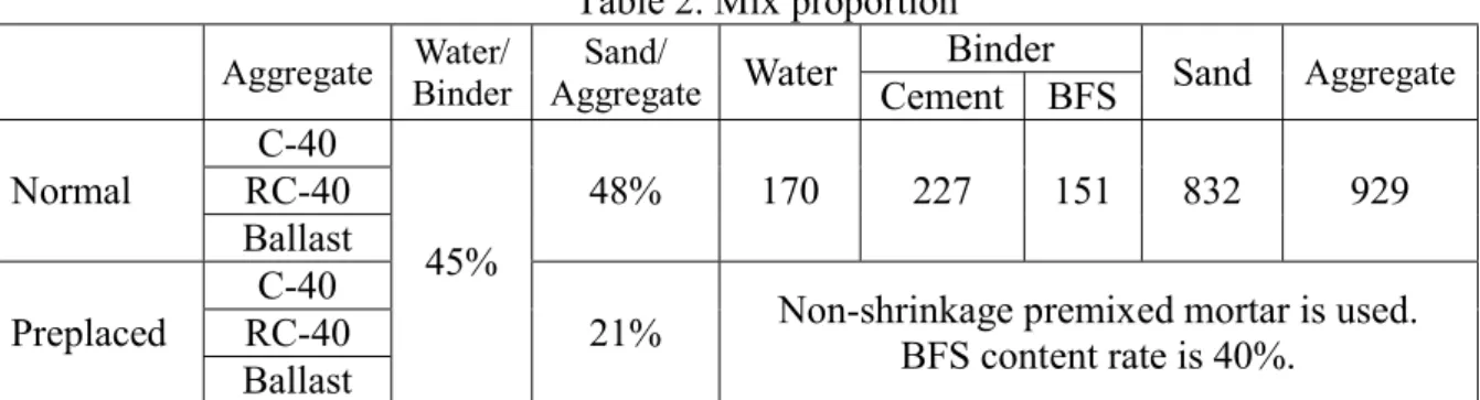
In Table 2, the specified mix proportion are indicated. Water-binder ratio is 45%. The mortar used for preplaced concrete is a non-shrinkage premixed mortar and contains 40% of ground granulated blast-furnace slag (BFS). Therefore, in normal concrete, the replacement ratio of BFS was also set to 40%.
Table 2. Mix proportion Aggregate Water/
Binder Sand/
Aggregate Water Binder
Sand Aggregate Cement BFS
Normal
C-40
45%
48% 170 227 151 832 929
RC-40 Ballast Preplaced
C-40
21% Non-shrinkage premixed mortar is used.
BFS content rate is 40%.
RC-40 Ballast
Surface dry density (g/cm
3)
Specific surface area
(cm
2/g) Grading Absorption Solid content
C-40 2.56 3.11 Good 2.2% 58.3%
RC-40 2.39 2.69 Good 5.0% 58.2%
Ballast 2.68 1.63 Bad 1.2% 58.1%
0%
20%
40%
60%
80%
100%
5 10 15 20 25 30 35 40 P er ce nt ag e of a gg re ga te pa ss ed th ro ug h
Particle size (mm) C-40
RC-40 Ballast
0%
20%
40%
60%
80%
100%
5 10 15 20 25 30 35 40 P er ce nt ag e of a gg re ga te pa ss ed th ro ug h
Particle size (mm) C-40
RC-40
Ballast
2.3. Testing Methods and Sample Size 2.3.1 Compressive strength test
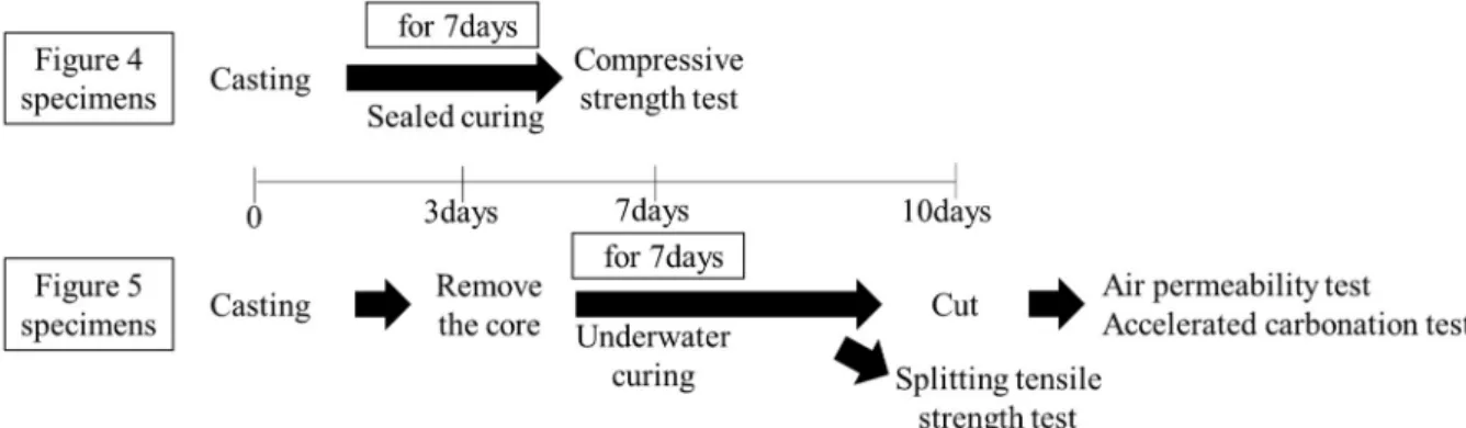
The specimens for compressive strength test were cast using formwork as shown in Figure 4. This test was performed on 3 specimens from the same mix proportion.
2.3.2 Splitting tensile strength test
For splitting tensile strength test, specimens were prepared by removing cores from the sample (size ofφ100mm×200), as shown in Figure 5. This test was conducted by removing 3 cores from the sample in the upper, middle and lower position.
2.3.3 Air permeability test
Air permeability test was performed by using specimens cut off the core. The core of Figure 5 was cut into four equal parts and made into size of φ100mm×50mm.
2.3.4 Accelerated carbonation test
Accelerated carbonation test is performed using specimens in Figure 5. The specimens were sealed letting only one side opened and placed in 5% carbon dioxide environment for 4 weeks.
After that, it was measured the carbonation depth of the specimen.
2.4. Curing Method of The Specimens
Figure 6 shows curing method and test flow. The curing is for 7 days. The specimens in Figure 5 were demolded after 3 days and the core as shown in the figure was removed. The splitting tensile strength test was done before cutting.
Figure 6. Test flow
Figure 4. Specimens size Figure 5. Specimens size
3. RESULTS AND DISCUSSION 3.1. Compressive Strength Test
Figure 7 shows the results of compressive strength test. Normal concrete was stronger than preplaced concrete. Preplaced concrete had the same strength for all aggregates. Therefore, in preplaced concrete, the kind of aggregate did not affect compressive strength.
Figure 7. The results of compressive strength test
3.2. Splitting Tensile Strength Test
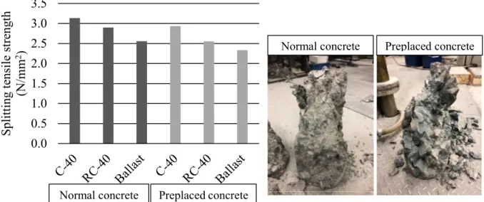
Figure 8 shows the results of splitting tensile strength test. Normal concrete and preplaced concrete showed the same trend. The concrete using C-40 had the strongest result for split tensile strength, and the concrete using ballast had the weakest result.
After this test, the appearance of specimens looked like Figure 9. Normal concrete was destroyed in the paste part. On the other hand, preplaced concrete was broken along the aggregate. Therefore, it was considered that the aggregate interface of preplaced concrete is weak.
Figure 8. The results of splitting tensile strength test Figure 9. The appearance after test 0
5 10 15 20 25 30
C-40 RC-40 Ballast C-40 RC-40 Ballast
C om pr es si ve s tr en gt h( N /m m
2)
Normal concrete Preplaced concrete
0.0 0.5 1.0 1.5 2.0 2.5 3.0 3.5
S pl it ti ng te ns il e st re ng th (N /m m
2)
Normal concrete Preplaced concrete
Normal concrete Preplaced concrete
3.3. Air Permeability Test
Figure 10 shows the results of air permeability test. For preplaced concrete, there was a large difference in air permeability coefficient due to the core removal position. Normal concrete had the same value. In addition, normal concrete had smaller value than preplaced concrete.
Considering the result for splitting tensile strength test, it is believed that the weak aggregate interface has pores connected and air can easily pass through that parts.
Figure 10. The results of air permeability test
3.4. Relationship between Air Permeability Coefficient and Compressive Strength
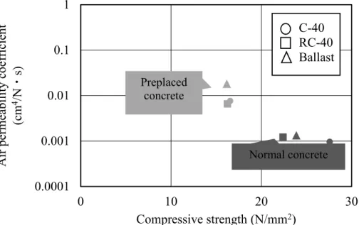
As Figure 11 shows, preplaced concrete and normal concrete tended to be different. In preplaced concrete, even if air permeability coefficient changed, compressive strength is almost constant. On the other hand, in normal concrete, even if compressive strength changed due to kind of aggregates, air permeability coefficient is almost constant.
Figure 11. Air permeability coefficient and compressive strength 0.0001
0.001 0.01 0.1
1
C-40 RC-40 Ballast C-40 RC-40 Ballast
A ir p er m ea bi li ty c oe ff ic ie nt (c m
4/N ・ s)
Normal concrete Preplaced concrete
0.0001 0.001 0.01 0.1 1
0 10 20 30
A ir p er m ea bi li ty c oe ff ic ie nt (c m
4/N ・ s)
Compressive strength (N/mm
2) C-40 RC-40 Ballast Preplaced
concrete
Normal concrete
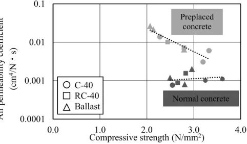
3.4. Relationship between Air Permeability Coefficient and Splitting Tensile Strength Figure 12 shows the relationship between air permeability coefficient and compressive strength. Preplaced concrete and normal concrete tended to be different. In preplaced concrete, there was a correlation between air permeability coefficient and compressive strength. The lower compressive strength, the easier the air is able to pass. Also, preplaced concrete using ballast had weak compressive strength and high air permeability. On the other hand, normal concrete didn’t have correlation between air permeability and compressive strength.
Figure 12. Air permeability coefficient and compressive strength
3.5. Carbonation
Figure 13 shows the result of accelerated carbonation test. In normal concrete, there is no much difference in carbonation depth by the kind of aggregate. However, in preplaced concrete, the difference was large depending on the kind of aggregate. Preplaced concrete used ballast was the most carbonated. It was considered that the air gaps were connected, and it was easier for preplaced concrete to carbonate. Because the results were different depending on the aggregate, it was assumed that the gaps at the aggregate interface were connected. Figure 12 shows relationship between air permeability coefficient and carbonation depth. The low correlation between the results of the air permeability test and the carbonation test are considered to be caused by the difference in pressure.
Figure 13. Carbonation depth Figure 14. Air permeability and Carbonation 0.0001
0.001 0.01 0.1
0.0 1.0 2.0 3.0 4.0
A ir pe rm ea bi li ty co ef fi ci en t (c m
4/N ・ s)
Compressive strength (N/mm
2) Preplaced
concrete
Normal concrete C-40
RC-40 Ballast
0 2 4 6 8 10
C ar bo na ti on d ep th ( m m )
Normal concrete Preplaced concrete
0 2 4 6 8 10
0.0001 0.001 0.01 0.1
C ar bo na ti on d ep th ( m m )
Air permeability coefficient(cm4/N・s)