A SIMPLE PROCEDURE FOR THE ACCURATE DETERMINATION OF STRESS IHTENSITY FACTORS BY FINITE ELEMENT
METHOD
by
Yukitaka MURAKAMI' (Received October 24, 1975) SYNOPSIS
A simple procedure for the accurate determination of stress intensity factors Ki, Kii by the conventional finite element method is proposed. The first step of the method is tocalculatethestress ag of the plate without a crack. The second step is to calculate the stress o,i.. of the plate with the crack. The value of(atip/ - o,) at the crack tip element is regarded to have the intimate relation with Ki, Kii.
Ki and Kii are determined from the value of (atip - o,) and a standard solution.
It is shown that the results obtained for many problems by the proposed method are in excellent coincidence with the analytical solutions. The erroris below 1 -- 30%) for the most cases.
1. INTRODUCTION
Although the stress intensity factors for various shapes and boundary conditions have been calculated, the most of solutions obtained by analytical methods are for the cases in which the shapes and the boundary conditions are rather simple.
The finite element method (FEM) is versatile for the variation of the shapes and boundary conditions. However, it has been thought that FEM is not suitable for crack problems because of the existence of stress singularity at crack tip. In spite of these circumstanees, the various method of the determination of stress intensity factors by FEM have been proposed. In the most of these methods, the special techniques to overcome the difficulty of the treatment of singular term are
adopted. These methods, however, can not easily be used, because they need the change of the calculation programs, special elements or the stress function.
In the present paper, a simple procedure for the accurate determination of stress intensity factors by FEM is proposed. The method does not need the special elements and many nodal points or elements. It is shown that stress intensity factors Ki, Kiican be accurately calculated by the simple procedure using the conventional FEM programs which are popular among mechanical engineers in recent
*Lecturer, Department of Mechanical Engineering, Kyushu Institute of Technology, Tobata, Kitakyushu, 804 Japan.
(23)
Em
in
phco
Ao
podi
LH
-h
.-ca
Åë=
p=
.I- ca op Åë
vkop LHo
gua
•• :
6E qo
.e--
-ed
-os -oed
p=
Åë
Nk
o7
-o
-pdi
E••-,
ca
Eh-r--;E.fin"
•I,lill/Li.,,'l•e../}//'lg,ll"i'•,/g/-,Ilg•A.cO=ne-N-elNAso.ptvnpcoL-J-SvnalouL-Jvv vÅëvp:odi.f.g`s'".E'.-ua=o,L:-ct.
g•g,.g,',d.
rEEIca
.2En vgb
Eminqx 8Z: s21{.,.,i•År.h-e
oord
v"oo U).
sts6.co=Eg.22fGo
gg•g
P"-
.S.8-E"+)OLJdiÅrh-"
=o-
g.,EE.3•{.-di.•8-gts•2-:EEg
g•t-:s,g,kg.'iz;Lr,L p=
e
O
6-al=.9p=ÅëÅr
tzgkSÅëv=otzlE
{E.g,t--,-ksfge.Åío=-senA':=coNOAptV5Åë"--Åë-vv
ota
tsMk=vo:odird-.GM""v.
g
U -rd .edg'sdi.e-cao'-ÅëHEO6
Exidi=k
kÅëcogG,fli.[TllZ-t-xNOLJ
:/Agx/di,
oo v
v"ÅëdicaÅë
pcaasq
vofG.nOe-ca=o•.-
E8•3
":e-IsOooNgvvr?6cavtcaOr--1-OnNO-:Nn.CN-"-J-cav-aeeAafosoEn-A-NA-di--p-vv g.og•'gi/,t
i•iÅr.Y,,8/L•2ggÅég
L-Ov ca
,kÅëv
=caÅë
vo odica
PAgÅre5 spo2
kO
8.Zdi.-
year.
2. REVIEW OF CURRENT RESEARCHES
In Table 1, the current methods of the determination of stress intensity factors by FEM are shown. They are classified into two kinds. One is the method in which the constant strain element(conventional element)is used and the other is the one in which the special element is used.
2.1 The methods on the basis of the conventional element.
The displacement functions for the the two-dimensional conventional finite elemet are
u=a1+a2X+a3Y
The determination of stress intensity factors by the displacement method, the stress method, the J-integral method, the energy method, the superposition method and the numerical experiment equation method are based on the conventional finite element.
The displacement and the stress method involve the correlation of the finite element displacement and the finite element stress distribution in the vicinity of crack tip with the well known crack tip displacement and the stress equations respectively. The J-integral method is based on the relation between the J-integral and the stress intesity factor. The energy method is based on the relation between the stress intensity factor and the strain energy release rate which is calculated from the two problemswith the slightly different crack length. The compliance method for determining stress intensity factors is similar to the energy method, as the energy release rate can also be related to the rate of change of compliance with crack extension.
The sufficient refinement of element meshes in the displacement and stress method may result in accurate stress intensity factors. HoWever, there is no assurance that the finite element solution on the basis of conventional element is accurate near crack tip [19].
The J-integral and the energy method are available in the problems in which the stress distribution in the vicinity of the crack tip is plain. Although in general these
methods are somewhat more accurate than the displacement and stress method for the same mesh, the determination of separate intensity components Ki, Kii can not be made [4-6,20].
Yamamoto et al [8] proposed a superposition method in which FEM is combined with an analytical solution and the singularity at the crack tip is determined with
the help of analytical solution indirecty. They have shown the effectiveness of the method for mary cases by the comparison with the analytical results already obtained.
And the method is being extended to the three-dimensional problems. However, it is laborious that the method always needs the selection of a suitable stress function and the special technique for individual problems. Another approach of superposition
(25)
method is proposed by Pian et al[21].
Miyata et al [13] proposed a numerical equation for the determination of stress intensity factors. They derived the equation from the correspondence of the stresses and displacements of the crack tip element which were calculated by FEM and the analytical function respectivsly. Although they assure the accuracy of the equation, the detail results are not shown yet. So long as the author carried out the calcrlation based on the equation, there are several cases in which the equation proposed were in poor agreement with the exact solutions.
2.2 The method on the basis of the special element.
Since the stress and the strain calculated by the conventional finite element method are constant in the crack tip element, the well known singularity in the vicinity of crack tip can not be found directly from the solution. Recently, alternative approaches for the direct and accurate determination of stress intensity factors have been developed by the help of special element[15-20]. In these methods, the special displacement functions which express the crack tip singularity are adopted in stead of the conventional one(Eq.(1)), and the stress intensity factors can be directly determined from the stress distribution or the displacement in the special element. The parameters which affect the accuracy of the specialelement method are the dimension and the number of the special elements[19,20].
3. A SIMPLE PROCEDURE FOR THE ACCURATE DETERMINATION OF STRESS INTENSITY FACTORS BY CONVENTIONAL FINITE ELEMENT METHOD.
We can not expect the accurate determination of stress intensity factors from the current simple method based on the conventional finite element. And the approaches on the basis of the special element or special techniques are not easy for common use as they need the change of calculation programs or the laborious consideration for individual problems.
Although it seems that these weak points of FEM is unavoidable so long as we use FEM for the calculation of stress intensity factors, a new simple procedure which enables us to determine the accurate stress intensity factors without losing the versatility of FEM is proposed in the present paper.
The stress concentration is in essence due to the release of the stress at the newly created free surface [26] .The so-called stress concentration factor a means the ratio of the summation(ag+a.)of the stress ag which exists at the root of notch or hole before the creation of free surface and the stress a. which is added by the creation of the new free surface (notch or hole) to ag (a=1+aa/ag).
The stress concentration at a crack tip is customarily expressed by stress intensity factor. The stress o,(the components: og., ogy, Tgx.)which exists at the
hypothetical crack tip before the creation of the crack is ignored because o, is very small in comparison with o. which is added at the crack tip by the creation of the crack. The value of 6, does not affect the accuracy of stress intensity factor when it is determined by analytical methods. However, if FEM is used for the de- termination of stress intensity factor, the value of 6, can not be ignored because 6, is included in the stress oti, (the components: atip., atipy, Ttip.y) of the crack tip element and the relative value of o, to 6ti. affects the accuracy of the stress intensity factor which is determined on the basis of oti.. Namely, when the relative value of o, to ati. is large(for example, in the case of coarse mesh), it becomes difficult to determine stress intensity factor accurately on the basis of oti..
In the present paper, the following procedure is proposed in order to eliminate this undersirable features. The first step of the method is to calculate the stress og of the element at the hypothetical crack tip in the plate without a crack. The second step is to calcu!ate the stress oti. of the crack tip element in the plate with a crack. The value of(otip-a.) at the crack tip element is regarded to have the intimate relation with stress intensity factors. The reasonableness of the method will be understood if the two problems, the crack in the uniform tension ao and that subject to internal pressure ao in which the stress intensity factors Ki are the same, are taken example. It is necessary to calibrate the standard correlation between ( oti,-og)and stress intensity factors before the method is applied to general problems.
In the present chapter, the determination procedure of opening mode stress intensity factor Ki is explained.
ut a
ttttt ttt tt
[]l
2W 2W
+ i!I
2W :
i I lec i i i i i4 ; i
Ca} (b} tc)
•Fig.1 Rectangular plate with a central crack.
The problem of the plate with a central crack(Fig.1(a))is used to determine the standard correlation between (ati.-og) and Ki. The problem of Fig.1(a) is equivalent with the superposition of Fig.1(b) and (c). As described above, if the problem of Figll(a) is solved by FEM, the uniform tensile stress ao in FigL1(b) which has no relation with K, is involved in the stress of the crack tip element.
Namely, in this case ag.==oo. The values(atipy-ag.)for the variety of the ratio e/
c(xo=2/c, Fig.2)and A(=c/W)were calculated by FEM. On the other hand, the k27)
stress intensity correction factor F(A) of Fig.1(a) which expresses Ki by Eq. (2) are exactly calculated by Isida [27].
:
t B c
10
.-,,L
/N tN
!N
!N
/t x
N
N.
) be t
11
' Xlt / tl
IL ... ..-J/ z.:J;i6
-b-- .-N-.. ..---- .. ..- -. .- `. -' --" d' o.1
o.ol o.1 x. 1,O
Fig.2 Mesh pattern at the surrounding Fig.3 Relations between ac, Tc and xo of a crack, xo=l/c
The approximate value of stress intensity factors Ki for general problems can be determined from the relation between(atip.-ag.)and F(A)ao for the various values of xo (=e/c). Namely, using the value a, which is given by
a.== (Ot!$y(i)Oog,y) (3)
and the newly calculated stresses atip, ag under the same value of xo for the problem in question, Ki is determined by the equation
K,= (atiPi-Ogi),/iiE- (4)
ac
, where the suffix I in atipi and agi means the normal stress components in the crack opening direction in otip and og.
The relation between a. and xo which is obtained from the calculation on Fig.
1(a) for the various mesh patterns(Appendix: Fig.Al, A2, A3 and A5)is shown in Fig.3 and Table 2. As seen in Fig.3 and Table 2, the value a, is small for the large value of xo (coarse mesh) and large for the small value of xo (fine mesh).
It is specially important that the value of A hardly affect the relation between a.
and xo.
Approximating lna, in Fig.3 with the seconddegreeformula of lnx. by least square method, the relation between a, and x. is expressed by Eq.(s)
a, =O.3033.x.Åq-L121-U•Oti547MXo) (s)
Table 2 The valuets of the stress atipi and ac of the crack tip element in Fig.1(a).
Lva li
2 F(a)27) OtltP
oo Oc
3. 0
O.5 O.2
O. 25 O.4
O. 03488 O. 43 O. 03261 O. 46 O. 03061 O. 49 O. 02885 O. 52 O. 02727 O. 55 O. 02586 O. 58 O. 02459 O. 61 O. 02344 O. 64 O. 02239 O. 67
1. 02459 1. 6377 O. 6224 1. 10937 2. 4068 1. 2681 1. 12941 6. 5470 4. 9114 1. 15199 6. 8653 5. 0145
!. 17746 7. 2178 5. 2807 1. 20622 7. 6175 5. 4861 1. 23879 8. 0415 5. 6842 1. 27579 8. 4582 5. 8459 1. 31802 8. 9523 6. 0335 1. 36653 9. 4839 6. 2084 1. 42264 10. 048 6. 3600
l
lilii
q Fig. 4
O. 125 O. 4
O.1 O.5
2. 75 O. 08333 O. 6 O. 07143 O. 7
O.0625 O.8
1. 10937 1. 18666 1. 30330 1. 48816 1. 8160
3. 4107 2. 1730 4. 0394 2. 5613 4. 8273 2. 9366 5. 8693 3. 2720 7.5033 3.5811 O. 2 O. 2083 1. 02675 2. 509 1. 470 O. 1429 O. 2917 1. 05436 3. 023 1. 919 O. 1111 O. 375 1. 09441 3. 542 2. 323 O. 0909 O. 4583 1. 15064 4. 104 2. 698 O. 0769 O. 5417 1. 22936 4. 740 3. 042 O. 0667 O. 625 1. 34142 5. 506 3. 359 O. 0588 O. 7083 1. 50825 6. 520 3. 660
Using Eq. (4) and(s), we can easily determ'ine the accurate stress intensity factor Ki with the conventinal finite element method.
The examples of calculated results are discussed in the next chaptar. The principle of the determination for shearing mode stress intensity factor Kii is similar to that of Fig. 2. The stress of the crack tip element means the mean value of the stresses of the element A and B(Fig. 2.).
It should be understood in the application of the method described above that the mesh pattern in the surrounding of the crack must be the same as or similar to that of Fig.2. The stress of the crack tip element means the mean value of the stresses of the element A and B (Fig. 2).
4. NUMERICAL RESULTS
4.1 A rectangular plate with symmetrical double edge cracks (Fig.4, Mesh patterns-Fig. Al and A5)
Stress intensity factors for the rectangular plate with symmetrical double edge cracks in tension are shown in Table 3. The results by Nisitani [28] and Bowie [29] are referred for the comparison. The results by the present method (FEM)
(29)
•which were calculated for the cases L/W =2.0, 3.0 are in good agreement with the solutions by Nisitani and Bowie. The stresses atipi and agi from which Fi are determined are shown in the tables of the appendix with the value of xo which is the ratio of the minimum side e of the crack tip element to the crack length c(This is the same for other problems.).
4.2 A rectangular plate with single edge crack(Fig.5, Mesh patterns-Fig. Al and A5)
Stress intensity factors for the rectangular plate with single edge crack in tension are shown in Fig.6 with the solutions by Nisitani [30]and Bowie [31].
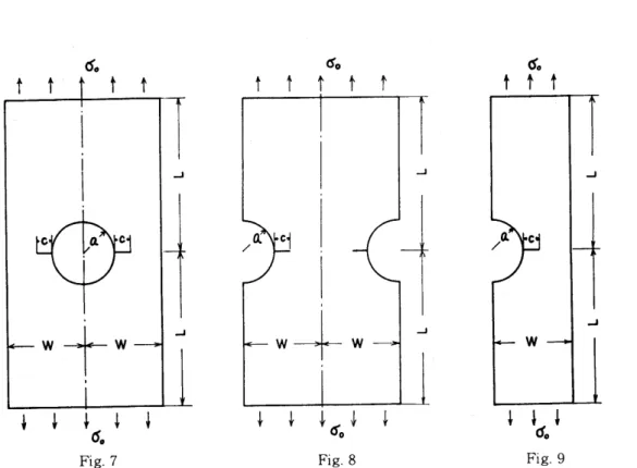
4.3 Stress intensity factors for the crack emanating from notch(Fig.7, 8 and 9, Mesh pattern-Fig.A6) .
Cettt Table3Fi of the rectangular plate with
symmetrical double edge cracks.
J Ki=Fi'aosl}iZi, A= c/W (Fig. 4)
c
w
A FEM Nisitani[28] Bowie[29]
- O. 2083 1. 12 1. 11 1.13
Fig.5 O. 2917 1. 11 Lll 1. 12
O. 375 Lll L13 1. 13
6.0
F:
5.0
4.0
3.0
2.0
1.0
iiqi O• 43 1• 12 L14 1• 14
O. 4583 1. 13 L15 1. 15 O. 46 1. 13 1. 15 L15
o O. 49 1. 15 L16 L16
Kz
Fr= O. 52 1. 17 1. 18 1. 17 d,M
O. 5417 1. 18 1. 19 1. 18
d
tcre ,1 O• 55 L20 1. 2o 1. lg
,g( O• 58 L22 1. 22 1. 21 1 O. 61 1. 25 1. 25 1. 23 st O. 625 1. 25 L26 1. 25
t
"6, Åí' O• 64 L29 L28 L26
d O. 67 1. 33 1. 31 1. 30
tt
,Sii .e,] L/W O' 7083 1• 36 1• 37 1• 35 cW 2L
t' eFEM 2o Fig-6 Fi of the edge crack
!tt in the rectangular plate.
,2 - Ntsitani , og e.h --- Bowieb'], 1.53 t
.t oFEM ,3.0
N
The method proposed in the chapter 3 can be successfully applied to the problems as Figs.7, 8 and 9. In the first step, the stress agi of the hypothetical
tt
c
,
,
ac
W -1(- W
,
J
.a cd
"t i}i
Fig. 7 Fig. 8 Fig. 9
crack tip element must be found from the calculation for the notched plate without cracks. In these cases, it should be considered that the stress ogi is different from the uniform tensile stress ao unlike the problems in sections 4.1(Fig.4)and 4.2(Fig.
5). In the second step, the stress otipi of the real crack tip element must be found from the calculation for the notched plate with cracks.The stress intesity factor K can be determined from the value of ogi , atipi and Eqs.(4).(5). The numerical results are
Table 4 Fi of the cracks emanating from the root of notch or hole.
Fi = Ki/aos/}i(57+TE;Y
(a) (b) (c) (d) (e) (f)
, , , , ,
c-a A={}-l+li].9.C - o
, , , , , ,
O.075 O.43 1. 13 [27] O.98 L12 O.82 2.33 1.83
O.15 O.46 L15 1.25 1.13 1.04 2.56 2.47
O.225 O.49 L18 1.36 L15 L12 2.81 2.86
O.3 O.52 1. 21 1.43 1.17 L17 3.11 3.22
O.375 O.55 L24 1.47 1.20 1.19 3.36 3.60
O.45 O.58 L28 1.51 1.22 1.22 3.85 4.01
O.525 O.61 1. 32 1.56 1.25 1.25 4.33 4.49
O.6 O.64 1. 37 L62 1.29 1.28 4.90 5.06
O.675 O.67 1. 42 1.68 1.33 1.32 5.77 5.76
(31)
shown in Table 4 with those of Figs.1, 4 and 5 in which notch or hole does not exist. It may be concluded from Table 4 that the stress intensity factors for the cracks emanating from the notches in Figs.8 and 9((d) and (f) in Table 4)can be approximated by those of the equivalent cracks in Figs.4 and 5((c) and (e) in Table 4), if the crack length c becomes greater than about O.25 times of the root radius of the notch. In the problem of Fig.7, however, the approxmation by the equivalent crack is not necessarily allowed. The same trends are showed in the solutinos by Newman [32]and Fuhring [33], when the relative value of a to the plate width W is large.
Table 5The values of Ki / aos/}iU in the problem of Fig. 8.
-g- A-alÅílc M,,,k,., Y &aMsa,M;IO12]
O. 075 O. 43 3. 11 3. 16 O. 15 O. 46 2. 88 2. 87 O. 225 O. 49 2. 61 2. 63
O.3 O. 52 2. 42 2. 44
O. 375 O. 55 2. 29 2. 29 O. 45 O. 58 2. 18 2. 18 O. 525 O. 61 2. 13 2. 12
O.6 O. 64 2. 09 2. 07
O. 675 O. 67 2. 08 2. 06
Table 5 shows the stress intensity tfa6tors which are defind by Ki/oos/ii6- with the results by Yamamoto et al. The largest difference between the results by the author and those by Yamamoto et al [12] is observed in the case of c/a =O.075.
Considering that in this case the crack part is divided into only two meshes (i.e., xo =O.5, refer to Table Al), it will be understood that the method proposed in
K:
F,' F;= 1•1215ct de ne F:'
c-)
X. d=3.747
XONo.gNo-4 q
OO O.5 c7n tO OO O-5 c/a tO
Fig. 10 Fig. 11
chapter 3 is not only simple but also accurate for coarse meshhs.
Figures 10, 11 and 12 show the variation of the stress intesity factors with c /a which are defined to becorne 1.0 when c . O. As seen in these figures, the calculated values consistently approach 1.0 when c/a --ÅrO. a in the figures mean the stress concentration factor based on ao . a for the notched plate of Fig.9 is defined by the stress of the element at notch root which is calculated by FEM. The similar values obtained by FEM for Figs.7 and 8 are a=3.711 and a=3.107 respectivey.
1.5
Fs'
F:'= 1.i21K
sda. xc
v
P
Fig. 13
O o.s c/a 1.0
Fig. 12
4.4 A crack in a circular plate subjected to concentrated forces (Fig. 13, Mesh pattern-Fig.A4) .
In order to obtain the stress intensity factors in the problem of Fig. 13, we must also calculate the stress a,i of the hypothetical crack tip element in the circular plate without the crack. In the next step, the stress atipi of the crack tip element in the same circular plate with the crack must be calculated. The procedure of the determination of stress intesity factors Ki is the same as that for the problems in sections 4,1--4.3. The numerical results are compared in Table 6 with the solutions by Isida [35]. The values obtained by FEM are in excellent coincidence with the solutions by Isida.
Thus, the present method can easily be applied to the special problem as the one in Fig.13 without the special technique and yet assures accurate stress intensity
factors.
(33)
The results are shown in Table 7. The symbolsein Fig.3 show the variation of Tc With Xo.
Now, when the stress components are obtained in the (x, y) coordinate, it is necessay to convert them into the components in (x',y')coordinate for the deter- mination of Ki and KH by the following equations.
oxt = li( ox + 6y) + li( ox - 6y)cos20 + Txy sin20
oyr=l}( ox+oy)-l}( ox-oy)cos20-Txysin20 (6)
1
rxryr= -lii(ox-oy)sin20+Txycos20
oti and ogi are given as follows.
otzpi=l}(oytA+o,,rB),ip •••••,•••8hxeistsst.rees when the crack (7)
ogi =S(oy'A+oytB)g •••••••••&hoeesStnroetSSexWisht9n the crack
Ki is determined from Eqs.(7) and (4).
And, the stresses Tt,pxry,and Tgx,yrare defined by the following equations.
Ttipx'yf=-l}-(TxtytA+Tx,y,B) t,p••••••••••••the stress when the crack. exists Tgx'y' = -l}-(Txryr+Txry,) g••••••••••••the stress when the crack does not exist.
Using these relations, Kii is deterrnined from the following equation,
yKll = rtipxryr - Tgx'y' vrii 6-
Tc
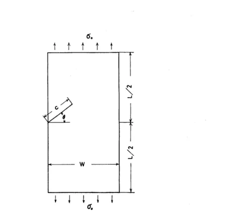
Table 8 shows the stress intensity factors Ki, KH determined on the basis of the procedure described above for o=45 and 30 degree (Fig.15).
Table 8 The stress intensity factors of the oblique crack (Fig. 15).
A = c/W.
0 A F,=
FEM
K, /aofic
[36]
Freese
F,==K,/
FEM
aoffc[36]
Freese
O.2 O.83 O.80 O.41
O.45
4se O.3 O.94 O.90
O.4 1.08 1.02 O.50
O.5 1.27 1.27 O.58
3oe
O.2 O.3 O.4 O.5
1.15 1.34 1.60 1.97
1.11 1.28 1.55 1.98
O.36 O.42 O.50 O.60
O.36 O.41 O.48 O.58
(35)
6o
t r t 1 t
Å~
de
Fig. 15 An oblique crack in the rectangular plate.
Therefore, once the values of ac and Tc are known as the function of xo, stress intensity factors in general problems can be calculated easily by the conventional finite element method. The formulation given in the present paper for a, is accurate enough for the engineering purpose.
However, as the formulation for Tc is incomplete in the stage of the present paper, it is expected to obtain the detailed standard value r. on the basis of reliable analytical solutions for the accurate determination of Kii.
5. CONCLUSION
In the present paper, a simple procedure for the accurate determination of stress intensity factors Kr, Kii by the conventional finite element method was proposed.
The procedures are summarized as follows.
(1) The first step of the method is to calculate the stress og of the element at the hypothetical crack tip of the plate without the crack. The boundary conditions in this step are the same as those of the real problem except for that at the crack boundary.
(2) The second step is to calculate the stress otip of the crack tip element in the real problem.
(3) The value.of(otip-a.)is regarded to have the intimate relation with the stress intensity factors Kr, Kii. Thus, Ki and Kn are determined from the value
of (otip-o,) and the calibrated values a, (Eq.(s), Fig.3) and T. (Fig.3, Table 7) which are obtained with the help of analytical solutions. The value of a. are formulated for convenience' sake (Eq.(5)).
In this way, Ki and Kii for various problems were calculated. The difference between the numerical results obtained in the present work and the analytical solutions obtained by the other workers is below 1--30/o for the most cases and the maximum difference is about 60/o at most.
As seen in the mesh patterns in Figs.Al-A8, the number of nodal points and elements used in the present work are rather less than those in other researches.
The maximum numbers of nodal points and elements are 242 and 415 respectively.
The number of meshes at the crack part are below 10 for the most cases and the extreme cases the stress intensity factors were determined with only 2 meshes at the crack part. Calculations were carried out under single precision.
The characteristics of the method proposed in the present paper are its accuracy and simpleness. Unlike the other methods which need special elements or special techniques, the present method can be easily carried out using the conventional finite element program which are commonly used in universities and companies. The applications to three-dimensional problems will be done in the future works.
ACKNOWLEDGEMENT
The author is indebted to Professors H.Nisitani and M.Isida of Kyushu University for valuable suggestions and discussions on the present work.
REFERENCES
1 ] S. K. Chan,L S. Tuba and W. K. Wilson, Engng. Frac. Mech.,2,1-17 ( 1970 ) [
[2] A.S.Kobayashi, D.E.Maiden and B.J.Simon,A reference in the referencs [20].
[3]D.JAyres and W.F. Siddall, A reference in the reference[20].
[4] V. B.Watwood, Nuclear Engng. and Design, 11, 323(1969).
[5] G.RAnderson, V.L.Ruggles and G.S.Stibor, Int. J.Frac. Mech., 7, 63-76(1971).
[6] MShiratori and M.Satoh, .Prelim. Proc. Japan Soc. Mech. Engrs., No.720-10, 21-24 ( 1972-8 ) .
[7 ] J. R Di xson and L P. Pook, Nature, 224, 166 ( 1969 ) .
[8] Y. Yamamoto and N.Tokuda, Prelim. Proc. Matrix Analysis of Structure, 62-65(1971-6).
[9] N.Tokuda and Y.Yamamoto, Soc. Naval Arch. Japan, 132, 349-379 (1972).
[10] Y. Yamamoto, Recent Advances in•Matrix Method of Struc. Analysis and Design, Univ.
of Alabama Press., 85 (1971).
[11] Y.Yamamoto and N.Tokuda, Int. J. Numerical Method in Engng., 6, 427 (1973) . [12] Y.Yamarnoto, Y.Sumi and K.Ao, Int. J. Frac., 10, 593-595 (1974).
[13] H.Miyata, S. Shida and S.Kusumoto, Prelim. Proc. for 15th Strength of Structure, (1973) .
[14] H. Miyata, S. Shida and S. Kusumoto, Prelim. Proc. Japan Soc. Mech. Engrs., No., 730-13, 183-186 (1973-10) .
[15] W.K.Wilson, A reference in the reference [20].
[16] P.D.Hilton and J.W.Hutchinson, A reference in the reference [20].
(37)
[17] E.Byskov, Int. J. Frac. Mech., 6, 159-167 (1970).
[18] D.MTracy, Engng. Frac. Mech., 3, 255-265 (1971) .
[19] P.D.Hilton and G.C.Sih, Mechanics of Fracture, 1, 426-483 (1973), ed. G.C.Sih, •Noordhoff.
[20] W.K.Wilson, Mechanics of Fracture, 1, 484-515 (1973), ed. G.C.Sih, Noordhoff.
[21] P.Tong., T.H.H.Pian and S. Lasry, Int J Numer. Method in Engng., 7, 297-308(1973) [22] Y.Ando, K.Iida, T.Kawai, G.Yagawa and F.Kikuchi, Trans. Japan Soc. Mech. Engrs., 37, 1803-1817 (1971) .
[23] H. Miyamoto and T. Miyoshi, Proc. IUTAM Symp., (1970).
[24] D.J.Hayes, Int. J. Frac. Mech., 8, 157-165 (1972).
[2s] S.G.Papaioannou, P.D.Hilton and R.A.Lucas, Engng. Frac. Mech., 6, 807-823(1974) [26] H.Nisitani and Y.Murakami, J. Japan Soc. Mech. Engrs., 75, 1081-1090 (1972).
[27] M.Isida, Engng. Frac. Mech., 5, 647-665 (1973).
[28] H.Nisitani, Prelim. Proc. Japan-U.S. Seminar on the strength and struc. of Solid Materials, (1974-10).
[29] O.L.Bowie, J. AppL Mech., 31, 208-212 (1964).
[30] H.Nisitani, Prelim. Proc. 50th Japan Soc. Strength and Frac. Mat., (1975-5) . [31] O.L.Bowie and D.MNeal, J. Appl. Mech., 708-709 (1965) .
[32] J.C. Newman, NASA TND-6376, 1-45.
[33] H.Fuhring, Int. J. Frac., 9, 328-331 (1973).
[34] M. Isida, Trans. Japan Soc. Mech. Engrs., 25, 1110-1124(1959), and private comunication [35] M.Isida, Prelim. Proc. Japan-U.S. Seminar on Combined Nonlinear and Linear Fracture Mechnics Application to Modern Engng. Struc., 2, l-18 (1974-8), Sendai.
[36] O.L.Bowie, Mechanics of Fracture, 1, 1-55 (1973), ed. G.C.Sih, Noordhoff.
Table Al The values of atii and agi•
t , , , , ,
'
Q
s .` , , , , ,
ea+c gatt2L!atgLI
gaal !a!ut!algLI gveaLI saLtip!-uag!-I g!alg!-I
- aoao aoao aoOo aoao aoao aooo
O.5O.43 6.54701.0 5.50403.1429 6.60131.0 4.68452.7151 12,625LO 9.95895.5627
O.25O.46 6.86531.0 6.93002.7070 6.85741.0 5.90472.3983 14.266LO 12.9604.6468 O,1667O.49 7.21781.0 7.83672.3896 7,13961.0 6.65042.1609 16.0461.0 15.4063.9372 O.125O,52 7.61751.0 8.54152.1421 7.4610LO 7.20441.9714 18.162LO 17.8283,3458
O.1O.55 8,04151.0 9.15141.9628 7.79371.0 7.6649L8335 20,6331.0 20.4552.8871 O.0833O.58 8.4582LO 9.70031.8216 8.11191.0 8.0617L7237 23.471LO 23.3722.4973 O.0714O.61 8.9523LO 10,2931.7046 8.49231.0 8,48941.6338 26.888LO 26,8342.1468 O.0625O.64 9.4839LO 10.899L6131 8,8954LO 8.9185L5656 30.9991.0 30.9471.8491 O.0556O.67 10.0481.0 11.567L5377 9.31391.0 9.3918L5122 35.8701.0 35,997L5835
Table A2 The stresses of the crack tip element of the oblique crack (Fig. 14 and 15).
ao = 1. 0, A = c/W.
2
0 - A oxA oyA TxyA axB ayB rxyB
4so
O. 25 O. 2 O. 36232 2. 7129 -O. 13381 L 1203 1. 5319 -O. O19918 O. 1667 O.3 O. 61954 3. 6336 -O. 24290 1. 6333 L 9474 -O. 061852 O. 125 O.4 O. 91366 4. 7406 -O. 354 16 2. 2725 2. 4485 -O. 10289 O. 1 O. 5 1. 2947 6. 1569 -O. 48957 3. 1450 3. 0845 -O. 16055 O. 25 O.2 O. 59408 3. 1482 O. 23593 1. 5293 1. 8235 -O. 29533 . O. 1667 O.3 o. 97079 4. 4359 O. 32272 2. 3358 2. 4580 -o. 45171
30 O. 125 O.4 1. 4491 6. 0944 O. 44758 3. 3929 3. 2768 -O. 65517 O.1 O.5 2. 1149 8. 3412 O. 64766 4. 9038 4. 3564 -O. 93588
Table A3 The stresses of a circular plate subjected to concentrated forc es (Fig. 13), A = c/b.
g A (-IS,'P) (tlll/ii)
. O. 25 O.2 L4227 O. 60068
O. 1667 O. 3 1. 8360 O. 59745 O. 125 O. 4 2. 2939 O. 58885 O.1 O.5 2. 8141 O. 56724 O. 0833 O. 6 3. 4406 O. 52947 O. 0714 O. 7 4. 2258 O. 45692 O. 0625 O. 8 5. 1571 O. 19305 (39)
Numbers of nodes = 149 Numbers of elements = 249 L/W = 2.0
Fig. Al
Nutubers of nodes = 175 Numbers of elements = 295 L/W = 2.7S
Fig. A2
Numbers of nodes = 101
Numbers of elements = 165 Numbers of nodes = 100
L/W=3.0 Numbers of elements=162
Numbers of nodes = 23g Numbers of nodes = 242 Numbers of elements = 412 Numbers of elements = 415
Fig. A5 Fig. A6
Numbers of nodes = 173 Numbers of nodes = 166 Numbers of elements = 311 Numbers of elements = 298 L/w = 2.0, e= 30 deg• L/w = 2.0, e= 45 deg•
Fig. A7 Fig. A8
(41)