SLOSHING PHENOMENA IN WATER RESERVOIR TANKS DUE TO LONG PERIOD‑LONG DURATION EARTHQUAKE GROUND MOTIONS
著者 ワキルアザドサラビ アリ
著者別表示 Vakilazadsarabi Ali journal or
publication title
博士論文本文Full 学位授与番号 13301甲第4157号
学位名 博士(工学)
学位授与年月日 2014‑09‑26
URL http://hdl.handle.net/2297/40536
DOCTORAL DISSERTATION
SLOSHING PHENOMENA IN WATER RESERVOIR TANKS DUE TO LONG PERIOD-
LONG DURATION EARTHQUAKE GROUND MOTIONS
Ali VAKILAZADSARABI
July 2014
博 士 論 文
SLOSHING PHENOMENA IN WATER RESERVOIR TANKS DUE TO LONG PERIOD-LONG DURATION
EARTHQUAKE GROUND MOTIONS
長周期,長継続時間地震動による貯水槽のスロッシング現象 に関する研究
金沢大学大学院自然科学研究科 環境科学専攻 環境計画講座
Student registration No.: 1123142414
Name: Ali VAKILAZADSARABI
Supervisor: Prof. Masakatsu MIYAJIMA
SUMMARY
There are a large number of storage tanks around the world, most of which are used as water and oil storage facilities. Different configurations of liquid storage tanks have been constructed. However, ground supported, rectangular tanks are more numerous than any other type because of their simplicity in design and construction. These structures play an important role in municipal water supply and firefighting systems. They can be easily constructed in different sizes to fulfill the capacity requirements. Rectangular tanks may be made of either concrete or steel.
Many storage tanks are considered as essential facilities and are expected to be functional after severe earthquakes. This is partly due to the need for water to extinguish fires that usually occur during such earthquakes.
The structural design criteria of liquid containing structures against earthquake are different from those of general building structures. Tanks require serviceability limit states such as leakage, deflection, and durability limit, due to the nature of their use.
Only few guidelines are presently available for earthquake-resistant design of liquid storage tanks. In addition, parts of these guidelines are not in full consistency with the rest.
Currently, ACI 350.3-06 standard in conjunction with ASCE 7-05 and ACI 371R-08 are used for seismic design of tanks. Most of the current codes and standards have adapted Housner’s method (Housner, 1957; 1963) for seismic analysis and design of tanks. There are some debates that the corresponding available guidelines are inaccurate in terms of the seismic induced loads on the tank wall which can consequently affect the required section properties of the earthquake-resistant structural system.
Most of the current codes including ACI 350.3-06 assume a rigid wall boundary condition in estimating the hydrodynamic forces acting on the tank wall. However, tank wall flexibility could increase the hydrodynamic pressure significantly as compared to the rigid wall assumption. As a result, more investigation regarding the effect of wall flexibility on seismic behavior of cylindrical liquid-filled tanks seem essential.
The poor seismic performance of both steel and concrete ground-supported water tanks under earthquake ground motions has been observed in major past earthquakes. In regions with the high seismic intensity many tanks have been severely damaged and some have collapsed with terrible outcomes. For example, severe damages suffered during the 1933 Long Beach, 1952 Kern County, 1964 Alaska, 1964 Niigata, 1966 Parkfield, 1971 San Fernando,1978 Miyagi prefecture, 1979 Imperial County, 1983 Coalinga, 1994
Northridge and 1999 Kocaeli earthquakes which revealed a complex behavior of ground- supported liquid storage tanks during seismic motions (Rinne (1967), Shibata (1974), Kono (1980), and Sezen and Whittaker (2006)).
This weakness in seismic performance was also observed among water tanks. As, for example, one can refer to the poor performance of some water tanks having reinforced concrete shaft-type supports during the 2001 Bhuj (Rai (2002)) and the 1997 Jabalpur (Rai et al. (1997)) earthquakes in India. In the Bhuj earthquake, three elevated water tanks collapsed completely, and many more were damaged severely. Similar damage was also observed in the Jabalpur earthquake. Reviewing the available literature, one can say that little effort has been made to better identify the dynamic behavior of elevated tanks.
The reported damage due to previous seismic events could have happened due to the following three reasons:
1) Coupled motion of the tank shell and stored liquid due to the short-period component of the seismic wave. This behavior is referred to as bulging. Under such vibration, a large part of the stored liquid acts as inertial mass with a period much shorter than the sloshing natural period. Tank walls are expected to be subjected to considerable inertial force and dynamic fluid pressure as a result of this type of vibration.
2) Liquid sloshing due to the long-period component of the seismic wave. Sloshing response in tanks may have a long natural period of several seconds to a few tens of seconds. This phenomenon may result in highly localized pressure on the body of the tank, substantial uplifting pressure on the tank roof or may cause spillover of stored liquid in open top tanks. Sloshing response in tanks particularly depends on the tank geometry, dimensions and dynamic characteristics of the ground motion.
3) Loss of soil bearing capacity as a result of liquefaction which in turn could result in non-uniform settlement of the tank foundation.
The conventional method for earthquake-resistant design of water tanks is to increase the strength of the structure so that it can tolerate the design earthquake safely. As a result of this strengthening, higher seismic forces will be applied to the structure. Contrarily, the effect of seismic input can be significantly reduced using Menshin (earthquake reduction) method (Kumieda (1976), MITI (1980), and Aoyagi and Shiomi (1985)). The Menshin method is a technique for reducing the amplitude of seismic vibrations being exerted on the structure. Considering the large number and size of liquid storage tanks, any safe reduction in structural material results in economic benefit. In the Menshin technique, safety of the structure is ensured through adjusting the dynamic properties of the structure
properly. This could be implemented by either one or combination of the following methods:
1) “Natural period adjustment method” in which the seismic response of the structure is reduced by increasing its natural period far beyond the predominant periods of the input earthquake. This may be accomplished by either mounting the structure on certain flexible mounts such as elastomeric bearings or by making alterations in structural configuration/geometry leading to a more flexible structure design.
2) “Energy dissipation method” in which the input seismic energy is absorbed by means of energy absorbing devices attached to the structure. Devices such as lead-rubber bearings, viscous dampers, or friction dampers may be used for this purpose.
3) “Isolation method” in which the structure is decoupled from the ground by means of insulators. The structure may be free to slide easily if mounted on low friction pads.
Isolation could be implemented using fluids (floating type), sliding plates, or different types of bearings.
To find out the real behavior of fluid-structure in tanks, appropriate evaluation of the dynamic characteristics of ground motion and structure is essential. It is also necessary to employ a highly accurate method of dynamic analysis. In this study rigorous finite element method (FEM) and smoothed particle hydrodynamics (SPH) to simulate the precise three-dimensional behavior of the tanks involving nonlinear behavior of devices is used. Using these techniques, one can therefore estimate the seismic response of tanks taking into account the long period-long duration ground motions in detail.
The main challenge in predicting the seismic behavior of liquid-filled structures are the identification of the vibration response of the tank taking into account the fluid-structure interaction (FSI). A dynamic study of such tanks must allow for the motion of the water relative to the tank, as well as the motion of the tank relative to the ground. In this study, different numerical techniques are employed for dynamic analysis of fluid domain.
For tanks which are closed and fully filled with water or are completely empty, the behavior of the tank may be well estimated as a one-mass system. However, usually the tanks are partially filled with water. In this case, the tank has a free water surface and thus, there will be the sloshing of the water free surface during a seismic motion, which makes the behavior of the tank-liquid system a complicated coupled problem. In this case, the dynamic behavior of the tank may be quite different. For certain proportions of the tank- liquid system, the response of the system is dominated by the sloshing of the water, on the other hand, there are other preparations that the sloshing may have minor contributions in
response. Therefore, an understanding of the seismic behavior of liquid-filled tanks requires an understanding of the hydrodynamic pressures and forces associated with the oscillating water. These pressures and forces depend on the characteristics of the ground motion, the properties of the contained liquid, and the geometrical and physical properties of the tank itself.
In this study, the numerical techniques are used to investigate the seismic response of ground-supported as well as water tanks during long period-long duration ground motions.
The results of this research will provide some useful information regarding the actual behavior of sloshing phenomena in tanks under seismic motions. This study will also lead to some recommendations for more accurate seismic analysis and design of water tanks.
ACKNOWLEDGMENTS
None other than my advisor, Professor Masakatsu Miyajima, can top the list of people I would like to take the opportunity here to thank. He accepted me into his environment and guided me through with his unlimited patience and energy. His support, guidance, and advice have been invaluable and deserve a special recognition. Thank you for your continuous support and advice throughout the past years. It has been an extremely educational and rewarding experience. I have enjoyed the enthusiasm and energy that you have brought towards all aspects of my life at Kanazawa University. I have enjoyed working with you tremendously and I hope we will continue to do so for years to come.
I am also very grateful to my dear professors in the Earthquake Engineering laboratory;
Dr. Ikemoto and Dr. Murata. It has been a privilege to have all of them participated in this important part of my life’s work. You have been sources of inspiration and support in various stages of my dissertation. Without your suggestions, timely advice, and comprehensive understanding of various aspects of my problems, my work would not have taken this shape and direction.
I would like also to thank committee members of this dissertation: Professors Masakatsu Miyajima, Ryoko Ikemoto, Takehisa Saito and Toshikazu Ikemoto from Kanazawa University, and Professor Junji Kiyono from Kyoto University for their critical reading and helpful argue.
Special words of thanks apply to my dear friend, Mr. Yavar Ghasempour for his invaluable help in the FEM code analysis and my dear uncle Mr. Vahid Hamdipour for always taking time to discuss about my research, my results, and our lives.
Thanks are also to Kanazawa University and JGC Company for providing the financial support during my study in Kanazawa University.
My admiration and gratitude go out to my family for supporting my study and encouragement throughout my life. I am grateful for their unfailing love and support that has been very rewarding. I attribute my success to their reassuring love and sacrifice.
Thanks are also to Dr. Abdolhossein Fallahi and Dr. Mohammad Hossein Erami for introducing me to Professor Miyajima and supporting me during my studies in Kanazawa University.
STUDY OF SLOSHING PHENOMENA IN WATER RESERVOIR TANKS DUE TO LONG PERIOD-LONG
DURATION EARTHQUAKE GROUND MOTIONS
TABLE OF CONTENTS
SUMMARY ... i
ACKNOWLEDGMENTS ... v
List of Figures ... x
List of Tables ... xiii
1. INTRODUCTION ... 1
1.1. General remarks ... 1
1.2. Earthquake damage to liquid storage tanks ... 1
1.3. A brief review of studies on response of water tanks subjected to sloshing phenomena ... 5
1.3.1. Long period & long duration ground motions ... 5
1.3.2. Response of ground-supported tanks ... 8
1.3.3. Numerical models ... 14
1.3.3.1. Boundary Element Method (BEM) ... 15
1.3.3.2. Mesh-based methods ... 16
1.3.3.3. Meshless methods ... 21
1.4. Codes and standards ... 23
1.5. Objectives and scope ... 26
1.6. Research significance ... 27
1.7. Thesis layout ... 28
References ... 30
2. Numerical modeling of water-tank interaction ... 32
2.1. General remarks ... 32
2.2. Introduction of fluid-structure governing equations ... 33
2.3. Material definitions ... 34
2.4. Explicit dynamic analysis ... 35
2.5. Stable increment time ... 36
2.6. Application to CEL ... 37
2.6.1. Contact interactions ... 37
2.6.2 Volume of Fluid Method (VOF)... 39
2.6.3. Boundary conditions and loads ... 43
2.6.4. Mesh ... 44
2.6.4.1 Displacement hourglass scaling factors... 45
2.6.4.2. Bulk viscosity scaling factors And ... 45
2.6.4.3. Mesh size ... 46
2.7. Application to SPH ... 46
2.7.1. Boundary conditions ... 48
2.7.2. Artificial viscosity ... 50
2.7.3. SPH kernel interpolator ... 50
2.7.4. Computing the particle volume ... 50
2.7.5. Smoothing length calculation ... 51
2.7.6. Interactions ... 51
2.7.7. Elements ... 52
2.7.8. Limitations of SPH method ... 53
2.7.9. Using section controls for specifying other SPH formulation parameters ... 54
2.8. Summary ... 55
References ... 56
3. Sloshing in water reservoir tanks due to harmonic motions ... 57
3.1. General remarks ... 57
3.2. Experimental setup ... 57
3.2.1. Experimental facilities ... 57
3.2.2. Water Tank ... 58
3.2.3. Shake table ... 58
3.2.4. Wave probes ... 59
3.2.5 Pressure sensor ... 60
3.2.6 High speed camera ... 60
3.2.7. Other considerations ... 61
3.3. Sloshing experiments and comparison with numerical and analytical solutions ... 61
3.3.1. Analytical formulations for sloshing in tank subjected to harmonic motion ... 62
3.3.2. Experiments of sloshing waves in the filling tank ... 63
3.3.3. Free surface profiles ... 64
3.3.4. Sloshing wave height and pressure ... 65
3.4. Discussion ... 72
3.5. Summary ... 73
References ... 74
4. Sloshing phenomena in tanks due to seismic ground motions ... 76
4.1. General remarks ... 76
4.2. Long periods-long duration ground motions ... 77
4.2.1 Tokachi-Oki (2003) ... 77
4.2.2 Tohoku earthquake (2011) ... 79
4.3. Modelling of fluid (water) reservoir in terms of seismic loading ... 82
4.4. Dynamic responses of the reservoir wall due to changing the stiffness of the reservoir wall ... 83
4.4.1. Evaluation of the maximum stresses in the tank wall during the loading time ... 83
4.4.2. Evaluation of the maximum displacements in the tank wall during the loading time . 86 4.4.3. Evaluation distortion induced along the tank wall height... 88
4.5. Dynamic responses of tank wall due to changing the thickness of the reservoir wall ... 90
4.5.1. Evaluation of the maximum stresses on the tank wall during the loading time ... 90
4.5.2. Evaluation of the maximum displacements in the tank wall during the loading time . 93 4.5.3. Evaluation distortion induced along the tank wall height... 95
4.6. The effect of changes in reservoir geometry ... 98
4.6.1. Evaluation of the maximum stresses in the tank wall during the loading time ... 98
4.6.2. Evaluation of the maximum displacements in the tank wall during the loading time ... 101
4.6.3. Evaluation distortion along the height of tank wall ... 103
4.6.4. Evaluation of the maximum hydrodynamic pressure in the tank during the loading time ... 105
4.6.5. Evaluation of water free surface elevation ... 108
4.7. Effect of water filling depth in the reservoir on dynamic responses of the reservoir wall ... 110
4.7.1 Evaluation of the maximum stresses in the tank wall during the loading time ... 110
4.7.2. Evaluation of the maximum displacements in the tank wall during the loading time ... 114
4.7.3. Evaluation distortion along the height of tank wall ... 115
4.7.4. Evaluation of the maximum hydrodynamic pressure in the tank during the loading
time ... 118
4.7.5. Water free surface elevation ... 120
Summary ... 122
5. Summary, conclusions, and recommendations for future works ... 124
5.1. Summary ... 124
5.2.Conclusions ... 125
5.3. Recommendations for future studies... 128
APPENDIX A: LAMINA FLUID THEORY ... 130
A.1. Housner’s method ... 130
A.1.1. Impulsive pressure ... 130
A.1.2. Convective pressure ... 134
APPENDIX B: TEXT COMMAND FILES OF THE TANK’S PARAMETRIC MODEL ... 139
B.1. Input file for the tank’s parametric model using CEL method ... 139
B.2. Input file for the tank’s parametric model using SPH method... 144
List of Figures
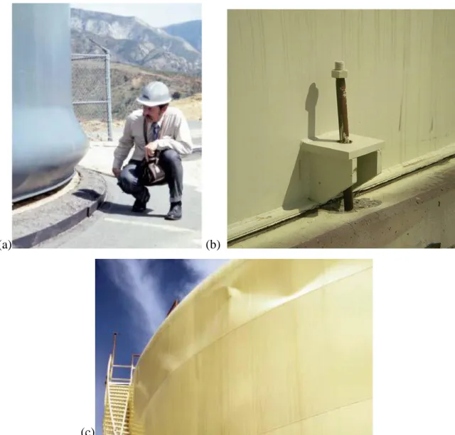
Fig. 1.1. Common damage modes: (a) Elephant-foot buckling, (b) Inelastic stretching of an anchor bolt at the tank base (c) Sloshing damage to the upper shell of the tank (adapted from Malhotra
et al. (2000) and Malhotra (2000)) ... 4
Fig. 2.1.Fluid domain ... 33
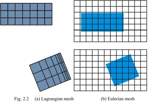
Fig. 2.2 (a) Lagrangian mesh (b) Eulerian mesh ... 38
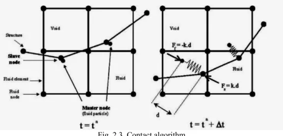
Fig. 2.3. Contact algorithm ... 39
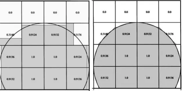
Fig. 2.4. Steps taken to calculate Volume Fraction F ... 40
Fig. 2.5. Comparison between the SLIC and PLIC surface reconstruction algorithms ... 41
Fig. 2.6. Local height function h ... 42
Fig. 2.7.Kernel function. ... 49
Fig.3.1. Experimental apparatus and working principle ... 58
Fig.3.2. Definition of parameters for liquid sloshing in a rectangular tank ... 58
Fig.3.3. Fixing tools of rectangular tank on the shake table ... 59
Fig.3.4. Schematic Diagram and picture of wave probe ... 60
Fig. 3.5. Tank with pressure sensor mounted ... 60
Fig.3.6. Free surface profiles of SPH, Experimental and CEL models under sinusoidal excitation with amplitude of 0.4 m.s-2 at different times. ... 65
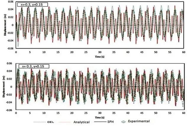
Fig.3.7. Time histories of sloshing wave height two end points obtained by CEL, Analytical, SPH and experimental methods with the frequency of 1.042 Hz (Resonant frequency) ... 68
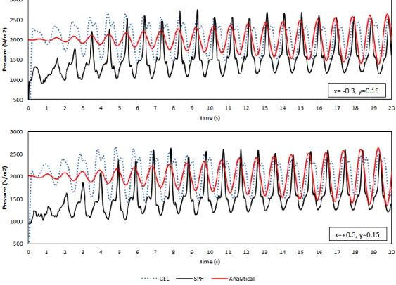
Fig. 3.8. Pressure time histories at two end location of the tank wall obtained by CEL, Analytical and SPH methods with a frequency of 1.042 Hz (Resonant frequency) ... 69
Fig. 3.9. Time histories of sloshing wave height two end points obtained by CEL, Analytical, SPH and experimental methods with the frequency of 0.4 Hz... 70
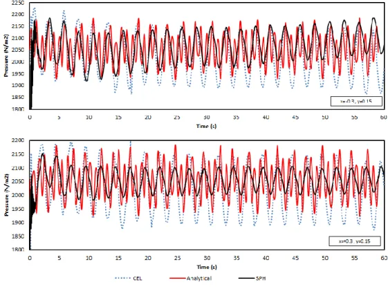
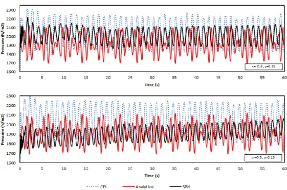
Fig. 3.10. Pressure time histories at two end location of the tank wall obtained by CEL, Analytical and SPH methods with the frequency of 0.4 Hz ... 71
Fig. 3.11. Pressure time histories at two end location of the tank wall obtained by CEL, Analytical and SPH methods with the frequency of 0.8 Hz. ... 72
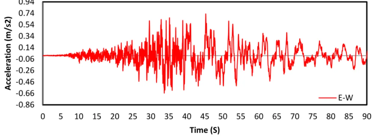
Fig. 4.1.Section of EW acceleration seismograms observed at Tomakomai stationalong a propagation path from the 2003 Tokachi-Okiearthquake (K-NET) ... 78
Fig. 4.2.Section of NS acceleration seismograms observed at Tomakomai stationalong a propagation path from the 2003 Tokachi-Okiearthquake (K-NET) ... 78
Fig. 4.3.Section of UD acceleration seismograms observed at Tomakomai stationalong a propagation path from the 2003 Tokachi-Okiearthquake (K-NET) ... 78
Fig.4.4. Velocity response spectra for 2003 Tokachi-Oki earthquake in all directions (K-NET) ... 79
Fig.4.5. Acceleration response spectra for 2003 Tokachi-Oki earthquake in all directions (K-NET) ... 79
Fig. 4.6.Section of EW acceleration seismograms observed at Tomakomai stationalong a propagation path from the 2003 Tokachi-Okiearthquake (K-NET) ... 80
Fig. 4.7.Section of EW acceleration seismograms observed at Tomakomai stationalong a propagation path from the 2003 Tokachi-Okiearthquake (K-NET) ... 80
Fig. 4.8.Section of EW acceleration seismograms observed at Tomakomai stationalong a propagation path from the 2003 Tokachi-Okiearthquake (K-NET) ... 81
Fig.4.9. Velocity response spectra for 2011 Tohoku earthquake in all directions (K-NET) ... 81 Fig.4.10. Acceleration response spectra for 2011 Tohoku earthquake in all directions (K-NET) .. 82 Fig.4.11. The maximum envelope stresses in Tank wall due to Tohoku earthquake (effect of changing material stiffness) ... 85 Fig. 4.12. The maximum envelope stresses in Tank wall due to Tokachi-OKi earthquake (effect of changing material stiffness) ... 85 Fig.4.13. Stress distribution in tank no.2 while the maximum stress occurred (effect of changing material stiffness) ... 86 Fig.4.14. Stress distribution in tank no.12 while the maximum stress occurred (effect of changing material) ... 86 Fig. 4.15. Maximum envelope displacements in tank in x direction during Tokachi-oki earthquake ... 87 Fig. 4.16. Maximum displacements in tank in Y direction during Tokachi-oki earthquake ... 88 Fig. 4.17. Distortion induced along the tank wall height due to Tohoku earthquake in longitudinal and lateral direction (effect of wall material). ... 89 Fig. 4.18. Distortion induced along the tank wall height due to Tohoku earthquake in longitudinal and lateral direction (effect of wall material). ... 90 Fig.4.19. The maximum envelope stresses in tank wall due to Tohoku earthquake (effect of changing wall thickness) ... 92 Fig.4.20. Stress distribution in tank no.3 while the maximum stress occurred (effect of changing wall thickness) ... 92 Fig.4.21. The maximum envelope stresses in Tank wall due to Tokachi-Oki earthquake (effect of changing wall thickness) ... 93 Fig.4.22. Stress distribution in tank no.4 while the maximum stress occurred (effect of changing wall thickness) ... 93 Fig.4.23. Maximum envelope displacements in tank in x direction during Tokachi-Oki earthquake (effect of changing wall thickness) ... 94 Fig.4.24. Maximum envelope displacements in tank in Y direction during Tokachi-Oki earthquake ... 95 Fig. 4.25. Distortion induced along the tank wall height due to Tohoku earthquake in longitudinal (a) and lateral (b) direction (effect of changing wall thickness). ... 96 Fig. 4.26. Distortion induced along the tank wall height due to Tokachi-Oki earthquake in
longitudinal (a) and lateral (b) direction (effect of changing wall thickness). ... 97 Fig.4.27. Deformation of wall in longitudinal direction due to Tokachi-Oki earthquake at the moment 52.50s... 97 Fig.4.28. The maximum envelope stresses in tank wall due to Tohoku earthquake (effect of changing tank geometry) ... 99 Fig.4.29. The maximum envelope stresses in tank wall due to Tohoku earthquake (effect of changing tank geometry) ... 100 Fig.4.30. Maximum Mises stress in Tank no.6 due to Tokachi-Oki earthquake at the moment of 60.25s. ... 101 Fig. 4.31 Maximum envelope displacements in tank in x direction during Tokachi-Oki earthquake (effect of changing tank geometry) ... 102 Fig. 4.32. Maximum envelope displacements in tank in Y direction during Tokachi-Oki earthquake (effect of changing tank geometry) ... 102
Fig. 4.33. Distortion induced along the tank wall height due to Tohoku earthquake in longitudinal
(a) and lateral (b) direction (effect of changing tank geometry). ... 104
Fig. 4.34. Distortion induced along the tank wall height due to Tokachi-Oki earthquake in longitudinal (a) and lateral (b) direction (effect of changing tank geometry). ... 105
Fig.4.35. The maximum envelope hydrodynamic pressure in tank due to Tohoku earthquake (effect of changing tank geometry) ... 106
Fig.4.36. The maximum envelope hydrodynamic pressure in tank due to Tokachi-Oki earthquake ... 107
Fig.4.37. Water free surface average elevation at right hand side of the tank due to Tohoku earthquake ... 108
Fig.4.38. Water free surface average elevation at right hand side of the tank due to Tokachi-Oki earthquake ... 109
Fig.4.39. The maximum envelope stresses in tank wall due to Tohoku earthquake ... 111
Fig.4.40. The maximum envelope stresses in tank wall due to Tohoku earthquake ... 112
Fig.4.41. Maximum Mises stress in Tank no.13 due to Tokachi-Oki earthquake at the moment of 52.6s. ... 113
Fig.4.42. Maximum Mises stress in Tank no.13 due to Tokachi-Oki earthquake at the moment of 54.1. ... 113
Fig.4.43. Maximum envelope displacements in tank in x direction during Tokachi-Oki earthquake ... 114
Fig.4.44. Maximum envelope displacements in tank in x direction during Tokachi-Oki earthquake ... 115
Fig. 4.45. Distortion induced along the tank wall height due to Tohoku earthquake in (a) longitudinal and (b) lateral direction ... 116
Fig. 4.46. Distortion induced along the tank wall height due to Tokachi-Oki earthquake in (a) longitudinal and (b) lateral direction ... 117
Fig.4.47. The maximum envelope hydrodynamic pressure in tank due to Tohoku earthquake . 119 Fig.4.48. The maximum envelope hydrodynamic pressure in tank due to Tokachi-Oki earthquake ... 120
Fig.4.49. Water free surface average elevation at right hand side of the tank due to Tohoku earthquake ... 121
Fig.4.50. Water free surface average elevation at right hand side of the tank due to Tokachi-Oki earthquake ... 122
Fig.A.1 Generalized symmetrical tank model; (a) x-y view, ... 131
(b) Slender tank special case with ... 131
Fig.A.2 Fluid element under consideration ... 132
Fig.A.3 Differential fluid element ... 132
Fig.A.4 Generalized symmetrical tank model; (a)tank plan, (b) tank section ... 135
Fig.A.5 Fluid element free body diagram; (a) Plan, (b) Section A-A ... 136
List of Tables
Table.1.1.Tank damages due to liquid sloshing... 8 Table 2.1.Values of parameters used to model water and air ... 35 Table.4.1.Definition and Specification of analytical models in this research ... 83 Table.4.2. Time and quantities of maximum and minimum displacements in tank wall in two perpendicular directions of applying ground motions ... 88 Table.4.3. Height and quantities of maximum deformation in a tank wall in two perpendicular directions of applying ground motions (Tohoku) ... 89 Table.4.4. Height and quantities of maximum deformation in a tank wall in two perpendicular directions of applying ground motions (Tokachi-Oki) ... 90 Table.4.5. Time and quantities of maximum and minimum displacements in tank wall in two perpendicular directions of applying ground motions ... 95 Table.4.6. Height and quantities of maximum deformation in a tank wall in two perpendicular directions of applying ground motions (Tohoku) ... 96 Table.4.7 Height and quantities of maximum deformation in a tank wall in two perpendicular directions of applying ground motions (Tokachi-Oki) ... 97 Table.4.8. Moment and the amounts of the maximum Mises stress in the tank wall due to Tohoku earthquake (effect of changing tank geometry) ... 99 Table.4.9. Moment and the amounts of the maximum Mises stress in the tank wall due to Tokachi-Oki earthquake ... 100 Table.4.10. Time and quantities of maximum and minimum displacements in tank wall in two perpendicular directions of applying ground motions ... 103 Table.4.11. Height and quantities of maximum deformation in a tank wall in two perpendicular directions of applying ground motions (Tohoku) ... 104 Table.4.12. Height and quantities of maximum deformation in a tank wall in two perpendicular directions of applying ground motions (Tokachi-Oki) ... 105 Table.4.13. Time and quantities of maximum hydrodynamic pressure in a tank due to Tohoku earthquake (effect of tank geometry) ... 107 Table.4.14. Time and quantities of maximum hydrodynamic pressure in a tank due to Tokachi- Oki earthquake ... 108 Table.4.15. Time and quantities of maximum hydrodynamic pressure in a tank due to Tohoku earthquake ... 109 Table.4.16. Time and quantities of maximum hydrodynamic pressure in a tank due to Tohoku earthquake ... 109 Table.4.17. Moment and the amounts of the maximum Mises stress in the tank wall due to Tohoku earthquake ... 111 Table.4.18. Moment and the amounts of the maximum Mises stress in the tank wall due to Tohoku earthquake ... 112 Table.4.19. Time and quantities of maximum and minimum displacements in tanks wall in two perpendicular directions of applying ground motions ... 115 Table.4.20. Height and quantities of maximum deformation in a tank wall in two perpendicular directions of applying ground motions (Tohoku) ... 117
Table.4.21. Height and quantities of maximum deformation in a tank wall in two perpendicular directions of applying ground motions (Tokachi-Oki) ... 118 Table.4.22. Time and quantities of maximum hydrodynamic pressure in a tank due to Tohoku earthquake ... 119 Table.4.23. Time and quantities of maximum hydrodynamic pressure in a tank due to Tokachi- Oki earthquake ... 120 Table.4.24. Time and quantities of maximum hydrodynamic pressure in a tank due to Tohoku earthquake ... 121 Table.4.25. Time and quantities of maximum hydrodynamic pressure in a tank due to Tokachi- Oki earthquake ... 122
1. INTRODUCTION
1.1. General remarks
One of the critical lifeline structures which have become widespread using during the recent decades is liquid storage tanks. These structures are extensively used in water supply facilities, oil and gas industries and nuclear plants for storage of a variety of liquid or liquid-like materials such as oil, liquid natural gas (LNG), chemical fluids and wastes of different forms. Problems associated with liquid tanks involve many fundamental problems. The calculation of hydrodynamic forces on the wall of vibrating liquid tanks is an important issue of safeguarding the structural integrity of industrial tanks and vessels.
Sloshing phenomena have caused significant damages on these vital structures in previous seismic events. In addition, tanks rule is increasing on human life, so researchers attempt to set accurate analysis methods and safe design solutions for fluid tanks. This chapter delivers a brief review on outstanding relevant works, and by summarizing their results, concludes with some outlines for new studies followed by the present study.
In this chapter an extensive literature review on dynamic response of liquid containing structures is presented. In Section 1.2 seismic performance of liquid storage tanks and associated damage types suffered during actual seismic events is discussed. Section 1.3 reviews and summarizes the available literature on seismic response of liquid storage tanks. The significant contributions made by previous researchers are also explained. An overview on existing codes, standards, and guides used in design of liquid storage tanks along with a literature review on application of seismic isolation to liquid storage tanks are provided in Section 1.4.
1.2. Earthquake damage to liquid storage tanks
There are frequent reports regarding the damage to liquid storage tanks due to previous earthquakes in the literature. For instance, there were heavy damages to both concrete and steel storage tanks during the strong seismic events such as 1933 Long Beach, 1952 Kern County, 1964 Alaska, 1964 Niigata, 1966 Parkfield, 1971 San Fernando, 1978 Miyagi prefecture, 1979 Imperial County, 1983 Coalinga, 1994 Northridge, and 1999 Kocaeli earthquakes (Rinne (1967), Shibata (1974), Kono (1980), Manos and Clough (1985), and Sezen and Whittaker (2006)). Severe damage levels were also observed in elevated water tanks during the 1960 Chilean as well as the 1997 Jabalpur (Rai et al. (1997)) and 2001 Bhuj (Rai (2002) and Dutta et al. (2009)) earthquakes in India. During the Bhuj
earthquake, many elevated tanks suffered severe damages in terms of flexural cracks in the circumferential direction in their supporting shafts near the base. Three elevated water tanks located in the highest intensity shaking zones also collapsed. Anshel (1999) has also reported heavy damages to cylindrical buried concrete tanks due to the 1995 Kobe earthquake. An underground concrete tank was also damaged severely in the form of the collapse of the wall during the 1971 San Fernando earthquake (Jennings (1971)).
Failure mechanism of liquid storage tanks depends on different parameters such as construction material, tank configuration, tank type, and supporting mechanism. Reported damage to liquid containing structures (LCS) during past earthquakes fall into one or more of the following categories:
1) Buckling of the shell caused by excessive axial compression of the shell structure due to exerted overturning moment (elephant-foot buckling)
2) Deformation, cracks and leakage inside shell
3) Damage to the roof or the upper shell of the tank, due to sloshing of the upper portion of the liquid contained in tanks with insufficient free board provided between the liquid free surface and the roof
4) Spillover of the stored liquid
5) Failure of piping and other accessories connected to the tank because of the relative movement of the flexible shell
6) Damage to the supporting structure in elevated water tanks 7) Damage to the anchor bolts and the foundation system 8) Failure of supporting soil due to over-stressing
In the 1964 Niigata earthquake, several damage modes including damage modes 3 and 4 due to excessive sloshing, mode 8 due to liquefaction of the supporting soil as well as damage modes 7 and 5 became prominent.
In the 1964 Alaska and 1971 San Fernando earthquakes, the lower part of the side shell bulged all along the perimeter as a result of mode 1 (elephant-foot buckling). This buckling type damage generally happens due to the excessive overturning moment generated during the seismic event.
In cases where the tank contains hazardous materials, liquid spillover (damage mode 4) and fire subsequent to a major earthquake may result in even more severe damage than the earthquake itself. The extensive uncontrolled fire eruption during the Niigata earthquake at Showa Petroleum blazed for about 15 days, resulting in the main destruction of the plant and residential apartments (Niigata Nippo Co. (1964)). The
Niigata and Alaska earthquakes of 1964 resulted in considerable loss in the petroleum storage tanks. This significant loss attracted many practicing engineers and researchers to further investigate the seismic behavior of liquid storage tanks, especially when the stored liquid is a hazardous material such as petroleum.
As an example of damage mode 4, one can mention oil spill over into the harbor that happened to the Sendai Refinery of Tohoku Petroleum Company during the 1978 Miyagi earthquake (Hazardous Material Technology Standards Committee: Fire Defense Agency (1979)).
During the Northridge earthquake main lifeline facilities of the Los Angeles area experienced severe damage. Five steel tanks were also damaged in the San Fernando Valley area. Buckling was the prominent form of damage in all of the damaged tanks.
Several other tanks also suffered roof collapse due to the excessive sloshing of the stored liquid (Lund (1996)).
It is important to note that the damage mode in concrete tanks is different from that of steel tanks. Elephant-foot buckling, anchorage system failure, and sloshing damage to the roof and upper shell of the tank are the most common damages in steel tanks (see Figure 1.1).
In tanks found in practice, full base anchorage is not always a possible or economical alternative. Therefore, many tanks are either unanchored or partially anchored at their base. If the tank is not rigidly anchored to the ground, the generated overturning moment due to earthquake may be large enough to result in lift-off of the tank base. As the tank base falls back down after lift-off, high compressive stresses are generated in the wall near the base leading to elephant-foot wall buckling. This mode of damage is more common in steel tanks since they are generally more flexible than concrete tanks.
Some studies show that base lift-off in tanks having flexible soil foundations does not cause high axial compressive stresses in the tank wall. As a result, unanchored tanks flexibly supported at their base are less susceptible to elephant-foot buckling mode, but are more susceptible to uneven settlement of the foundation (Malhotra (1995) and Malhotra (1997A)).
On the other hand, damage mode 2 is the most common type of damage in concrete tanks.
Stresses caused by large hydrodynamic pressures together with the additional stresses resulted from the large inertial mass of concrete could cause cracking, leakage and ultimately failure of the tank. That is why the design criteria for concrete tanks are based on crack control.
It is worth noting that elevated water tanks are very susceptible to seismic excitations because of the concentrated large mass located at top of the shaft structure. As a result, strong lateral seismic motions may result in large tensile stresses on one side of the concrete shaft section which may eventually lead to severe cracking or even collapse of the concrete pedestal.
As mentioned before, many elevated tanks collapsed during the 1960 Chilean, 1997 Jabalpur and 2001 Bhuj earthquakes since insufficient reinforcement was provided in the shaft section.
(a) (b)
(c)
Fig. 1.1. Common damage modes: (a) Elephant-foot buckling, (b) Inelastic stretching of an anchor bolt at the tank base (c) Sloshing damage to the upper shell of the tank (adapted from
Malhotra et al. (2000) and Malhotra (2000))
The significance of preventing such damages has led to a great deal of research to be carried out on dynamic behavior of such structures. These research studies could result in a better comprehension of the part of complicated behavior of liquid containing structures under long period seismic excitations.
1.3. A brief review of studies on response of water tanks subjected to sloshing phenomena
In the last four decades, many researchers have studied on the sloshing problem. And herein, studies with the most advantageous modeling methods and distinguished findings about the most influencing parameters of sloshing phenomena on fluid tanks are introduced. In addition, their most considerable assumptions, effective shortcomings and progressive results are presented.
1.3.1. Long period & long duration ground motions
Previously, most structures in earthquake-prone regions were low-profile structures, and so relatively short-period (1 s or shorter) ground motions, with which these structures might be resonant, were important. However, considering the increasing number of large structures, such as high-rise buildings, storage tanks, suspension bridges, offshore oil drilling platforms, and recent base-isolated structures, long-period (1 to 10 s or longer) ground motions have been increasingly important (e.g., Kanamori 1979; Fukuwa 2008).
One of the worst examples of destruction caused by long period ground motion happen in Mexico City, close to another long period ground motion in this area the 1985 Michoacan earthquake (MW= 8.0; e.g., Beck and Hall 1986). The other one is the 2003 Tokachi-Oki earthquake (MW=8. 3) that occurred in Hokkaido, Japan (e.g., Koketsu et al. 2005).
The 2003 Tokachi-Oki earthquake was the first M 8-class event to be recorded by the Japanese nationwide strong ground motion seismograph networks, K-NET and KiK-net.
It was thus the first time that large-amplitude long-period ground motions, which are a characteristic of large earthquakes, were recorded at a high station density in Japan. The resulting dataset makes it possible to study the detailed features of shaking, such as the spatial variation in amplitudes of long-period strong ground motions.
The most important procedures issued for this phenomenon considering long period-long duration ground motions are as follows:
Hanks (1975)
Hanks recovered 234 components of long-period ground motion in the source region of the 1971 San Fernando earthquake (MW=6.6), and the neighboring Los Angeles basin in California. He coined the term “long-period strong ground motion” in this paper (Zama
1993). Long-period ground motions are caused by the specific characteristics in the magnitude of the earthquake, epicenter location and geological structure through which seismic waves propagate. Large subduction-zone earthquakes and moderate to large crustal earthquakes can generate far-source long-period ground motions in distant sedimentary basins with the help of path effects. Near-fault long-period ground motions are generated, for the most part, by the source effects of forward rupture directivity. Far source long-period ground motions consist primarily of surface waves with longer durations than near-fault long-period ground motions.
Shima (1970)
The predominant period of long-period strong ground motion can vary between earthquakes, meaning that it is necessary to consider the source and path effects as well as local site effects in the prediction of predominant periods of such ground motions at a certain site. Far-source long-period ground motion was identified, for the first time in Japan, in seismograms of the 1968 Tokachi-Oki earthquake (MW=8.2) observed with large amplitudes and a predominant period of 2.5 s at Hachinohe, northeastern Japan.
They were also observed by strong motion seismographs installed in the first super high- rise building in Japan. This building was located in Tokyo, 650 km from the earthquake source.
Trifunac and Brune (1970)
Trifunac and Brune observed long period ground motion in distant seismograms of the 1940 Imperial Valley earthquake (MS=7.1) in California. Both the Japanese and Californian authors attributed these far-source long-period ground motions of regional surface waves. The most obvious difference is the duration of ground motion. The far- source long-period ground motions continue for 1 min or longer, whereas the near-fault long period ground motions last only for 10 to 20 s.
Koketsu et al. (2005)
The worst example of destruction caused by long period ground motion occurred in Mexico City, 400 km from the 1985 Michoacan earthquake (MW= 8.0; e.g., Beck and Hall 1986). Another example is the 2003 Tokachi-Oki earthquake (MW=8.3) that occurred in Hokkaido, Japan.
Murata and Miyajima (2008)
Murata and Miyajima have considered that one of the causes of the unusual phenomena seems to be sloshing of water in receiving water tank. If sloshing of water in many
receiving water tanks occurred simultaneously, an abrupt increase in flow rate and a decrease in water pressure may be occurring. Occurrence of sloshing of water in receiving water tank depends on the dimensions of receiving water tank and the height of water in the tank. Murata and Miyajima have investigated dimensions of receiving water tank in a water distribution block of Osaka City and estimated the natural period of sloshing of the water. Figure 2.3 shows the cumulative percentage of natural periods of water in receiving water tank in case that the height of water is 3/4 and 1/2 of the height of the water tank. The height of water is variable and depends on the use of water. The natural period of sloshing is more than 1.0 second of more than 80% of the water tank in the direction of the long side of the water distribution block in Osaka City.
Fig. 2.3 Cumulative percentage of natural periods of water in receiving water tank
Ohta and Zama (2005)
The generation of long-period ground motion can be identified based on damage to large tanks.
This damage is caused primarily by sloshing of the liquid inside the tanks. Because the excitation of liquid sloshing appears to require long duration seismic ground motion, it can be linked to far- source long-period ground motion. They documented 14 cases of tank damage because of liquid sloshing (Table 1.1).
Table.1.1.Tank damages due to liquid sloshing
Earthquake Year MW Damage Reference
Kanto 1923 7.9 6,000 t oil tank Hirano (1982) Long Beach 1933 6.2 Water tank Steinbrugge (1970) Kern County 1952 7.5 Oil tanks Steinbrugge and Moran (1954)
Alaska 1964 9.2 Many oil tanks, fires Rinne (1967) Niigata 1964 7.6 Many oil tanks, fires FDMA (1965) Central Chile 1965 7.1 Oil tanks Shibata (1974) San Fernando 1971 6.6 Oil tanks Shibata (1974)
Miyagi-oki 1978 7.4 Oil tanks FDMA (1979)
Imperial Valley 1979 6.5 Oil tanks Horoun (1983) Coalinga 1983 6.2 Many oil tanks Manos and Clough (1985) Japan Sea 1983 7.7 Many oil tanks, fires Yoshiwara et al. (1984)
Kocaeli 1999 7.6 Many oil tanks, fires JSCE (2000) Chi-Chi 1999 7.7 Oil tanks Yoshida et al. (2000) Tokachi-oki 2003 8.3 Many oil tanks, fires Ohta and Zama (2005)
1.3.2. Response of ground-supported tanks
A comprehensive research work on dynamic behavior of liquid-filled tanks has been carried out both theoretically and experimentally. Initial studies involved analytical investigation of the dynamic response of liquid containing structures having rigid wall and supported on rigid foundations. Extensive study of the dynamic behavior of liquid containing structures started in the late 1940’s.
Jacobsen (1949) and Ayre (1951)
Jacobsen and Ayre studied the dynamic response of cylindrical tanks subjected to horizontal ground motions. They estimated the effective hydrodynamic masses and mass moments for the accelerated contained liquid.
Housner (1963)
In the early 1960s, Housner proposed a useful idealization for obtaining liquid response of rigid rectangular and cylindrical water tanks fully anchored to the rigid foundation and subjected to horizontal ground motion. The liquid was assumed to be incompressible and inviscid. This method is probably one of the most well-known procedures available in the literature. However, attention should be drawn to the effect of tank wall flexibility which is not considered in this simplified technique. Housner separated the tank hydrodynamic response into "impulsive" motion, in which the liquid is assumed to be rigidly attached to the tank and moves in unison with the tank shell, and "convective" motion, which is characterized by long-period oscillations and involves vertical displacement of the fluid free surface. Under seismic motions, impulsive water undergoes the same acceleration as
the ground. This component is believed to have a significant contribution to the base shear and base moment. In this study, Housner developed simple equations to approximate the hydrodynamic pressures in the tanks using lumped mass approach.
Many current standards and guides such as ACI 350.3-06 and ACI 371R-08 have adapted Housner's method with some modifications which were the results of subsequent studies by other researchers for seismic design of liquid storage tanks. As mentioned before Housner's method is not capable of accounting for the effect of tank wall flexibility.
Therefore, as an approximate method ACI 350.3-06 accounts for wall flexibility by determining the oscillating water mass components from the rigid tank solution and only using the amplified pseudo acceleration corresponding to the fundamental natural frequency of the system instead of the ground acceleration. This approximation may be unduly inaccurate for values of H/R (liquid depth/tank radius) greater than 1 (Veletsos (1984)).
Edwards (1969)
Edwards (1969) for the first time suggested a finite element method to be employed for estimating the seismic response of deformable liquid storage tanks. A cylindrical liquid storage tank with the height to diameter ratio of less than one was analyzed using the finite element technique. The proposed FEM was capable of accounting for the coupled interaction between the stored liquid and the elastic tank shell.
Epstein (1976)
Using Housner’s model, Epstein produced design curves for calculating the overturning moment due to hydrodynamic pressures in both rectangular and cylindrical storage tanks.
Veletsos (1974) and Yang (1976)
Veletsos and Yang showed that the flexibility of the tank shell could have a significant effect on dynamic forces induced by horizontal ground motion in liquid-filled cylindrical containers. It was concluded that the flexibility of the walls of such tanks has a substantial effect on the impulsive component of the response. Veletsos and Yang (1977) modified this method by using Flugge's shell theory (Flugge, 1960) in combination with the Rayleigh-Ritz procedure to calculate the natural frequencies of the liquid-shell system.
Both shell analysis and the simpler beam-type analysis were carried out.
Hunt and Priestley (1978)
The dynamic behavior of horizontally accelerated liquid storage tanks containing inviscid liquid was further investigated by Hunt and Priestley. Both rectangular and cylindrical configurations were examined. The results of the study led to the derivation of
mathematical equations regarding the contained fluid motion under dynamic excitations.
The displacement of liquid free-surface was measured experimentally for a cylindrical water tank tested on a shaking table and subjected to both sinusoidal and seismic excitations. The predicted theoretical results were in close agreement with those obtained through experiment.
Clough (1977)
Clough for the first time performed a series of experimental tests on large-scale thin- walled liquid storage tanks. The obtained hydrodynamic pressures were much larger than those proposed by Housner’s analytical method. The difference in pressures was believed to be due to the tank wall flexibility effect. Several other numerical and analytical studies taking into account the interaction between the flexible shell and the containing liquid were conducted among which significant contributions were made by Haroun (1980) and Barton and Parker (1987).
Haroun and Housner (1981)
Haroun and Housner studied the behavior of deformable liquid storage tanks using modal superposition analysis. In this study, the tank shell was modeled by finite elements and the fluid domain was treated mathematically using the boundary solution technique.
They also developed a mechanical model capable of including the effect of wall deformability. The proposed three-degree-of-freedom (DOF) mechanical model involved three equivalent lumped masses corresponding to the convective component contributed by the sloshing of the liquid, the impulsive component which varies in unison with the horizontal ground acceleration, and the short period component contributed by the deformable wall vibrations. The latter component is only present in flexible liquid containers. In a tank with the rigid wall boundary condition, only the first two components need to be considered. The study also showed that the tank wall deformability may result in the hydrodynamic pressures several times larger than those experienced in rigid wall tanks. Based on this study, design charts for estimating the equivalent lumped masses of the proposed mechanical model were derived. It was assumed that the liquid contained in the tank was incompressible and had irrotational flow.
Balendra et al. (1982)
Balendra et al presented a finite element analysis of an annular cylindrical tank with an axisymmetric elastic dome, using a FE code. The fluid inside the tank was considered as inviscid and incompressible. However, sloshing of the fluid was neglected.
Minowa (1980)
Minowa further studied the tank wall flexibility effect and the corresponding hydrodynamic pressure exerted on the tank shell. He also performed experimental studies on the dynamic behavior of rectangular liquid-filled tanks.
Haroun (1983)
Haroun also performed a series of experimental investigations, including forced and ambient vibration tests on flexible ground-supported cylindrical tanks. In order to determine the mode shapes of vibrations and corresponding natural frequencies, three full scale water storage tanks were tested. This study led to a better understanding of the dynamic behavior of liquid storage tanks.
Haroun (1984)
Haroun evaluated the dynamic response of rectangular concrete liquid storage tanks using the classical potential flow approach assuming a rigid wall boundary condition. The fluid was assumed to be homogeneous, incompressible and inviscid. The tank was assumed to be subjected to the simultaneous action of horizontal and vertical components of earthquake. Bending moments developed in the walls of rectangular liquid-filled tanks due to seismic excitation at their base were calculated. As a result of this study, theoretical equations to evaluate the internal moments in the tank wall were derived and numerical values of moment coefficients to be used in seismic design of rectangular tanks were tabulated.
Haroun and Tayel (1985)
Haroun and Tayel employed the finite element technique for investigating the dynamic behavior of cylindrical liquid storage tanks having elastic wall and subjected to vertical seismic excitations. The proposed method was based on the superposition analysis technique using the axisymmetrical, free vibration modes of the tank-liquid system. The axial and radial components of the wall displacement together with the resulting stresses were calculated. In obtaining the dynamic response of the tanks, the effect of liquid sloshing was ignored.
Veletsos and Tang (1990)
Veletsos and Tang studied the dynamic behavior of liquid containing tanks resting on flexible foundations through rigid base mats. The results of the study indicated that the translational and rocking vibrations of the tank base resulted in the extended impulsive period and also larger effective damping. They had previously concluded that soil-
structure interaction reduces the hydrodynamic effects in tanks subjected to vertical excitations.
Park et al. (1992)
Park et al used a coupled boundary element-finite element method (BEM-FEM) to study the dynamic behavior of concrete rectangular tanks. The dynamic response of the tanks was obtained using the time-history analysis method. Both impulsive and convective components were included.
Gupta (1995)
Coupled free vibration dynamics of cylindrical liquid storage tanks were studied by Gupta.
The vibration study of the container was made possible using Flugge’s exact equations of motion. The hydrodynamic pressure associated with the contained liquid was obtained using the velocity potential approach. The obtained results compared well with those calculated by Haroun and Housner method.
Kim et al. (1996)
Kim et al. used Rayleigh-Ritz method to study the dynamic response of a flexible rectangular liquid storage tank. In this study, the effect of sloshing component of the contained liquid was neglected.
Dogangun et al. (1997 and 2004)
The dynamic response characteristics of rectangular fluid containers were further studied by Dogangun et al. He used analytical methods as well as finite element method using the modified structural analysis program SAPIV to evaluate the dynamic response. The fluid domain was modeled by displacement-based fluid elements. Effect of tank wall flexibility on dynamic behavior of tanks was also investigated. The proposed model was capable of including the effects of fluid compressibility and free-surface sloshing motion. The obtained FE results were compared with those obtained through boundary-finite element method (BEMFEM) and the requirements of Eurocode-8.
Koh et al. (1998)
Koh et al. proposed a coupled BEM-FEM technique, including free-surface sloshing vibration, to investigate the dynamic behavior of three dimensional rectangular water storage tanks under horizontal ground motions. In their study, finite element method was employed to model the solid wall while the indirect boundary element method was used to model the fluid domain.