鳥取大学研究成果リポジトリ
Tottori University research result repository
タイトルTitle Influence of the structure of the anion in an ionicliquid electrolyte on the electrochemical performance of a silicon negative electrode for a lithium-ion battery
著者
Auther(s) Yamaguchi, Kazuki; Domi, Yasuhiro; Usui, Hiroyuki;Shimizu, Masahiro; Matsumoto, Kuninobu; Nokami, Toshiki; Itoh, Toshiyuki; Sakaguchi, Hiroki
掲載誌・巻号・ページ
Citation Journal of Power Sources , 338 : 103 - 107 刊行日
Issue Date 2017-01-15
資源タイプ
Resource Type 学術雑誌論文 / Journal Article 版区分
Resource Version 著者版 / Author 権利
Rights Copyright © 2017 Elsevier B.V. All rights reserved.This manuscript version is made available under the CC-BY-NC-ND 4.0 license https://creativecommons.org/ licenses/by-nc-nd/4.0/
DOI 10.1016/j.jpowsour.2016.10.111
1
Influence of the Structure of the Anion in an Ionic Liquid
Electrolyte on the Electrochemical Performance of a Silicon
Negative Electrode for a Lithium-Ion Battery
Kazuki Yamaguchia,b, Yasuhiro Domia,b, Hiroyuki Usuia,b, Masahiro Shimizua,b,Kuninobu Matsumotoa,b, Toshiki Nokamia,b, Toshiyuki Itoha,b, and Hiroki Sakaguchia,b,*
aDepartment of Chemistry and Biotechnology, Graduate School of Engineering, Tottori University
4-101 Minami, Koyama-cho, Tottori 680-8552, Japan
bCenter for Research on Green Sustainable Chemistry, Tottori University
4-101 Minami, Koyama-cho, Tottori 680-8552, Japan
*Corresponding author Tel./Fax: +81-857-31-5265, e-mail: [email protected]
2 Abstract
We investigated the influence of the anions in ionic liquid electrolytes on the electrochemical
performance of a silicon (Si) negative electrode for a lithium-ion battery. While the electrode
exhibited poor cycle stability in tetrafluoroborate-based and propylene carbonate-based electrolytes,
better cycle performance was achieved in bis(fluorosulfonyl)amide (FSA–)- and
bis(trifluoromethanesulfonyl)amide (TFSA–)-based electrolytes, in which the discharge capacity of a
Si electrode was more than 1000 mA h g–1 at the 100th cycle. It is considered that a surface film
derived from FSA–- and TFSA–-based electrolytes effectively suppressed continuous decomposition
of the electrolyte. In a capacity limitation test, a discharge capacity of 1000 mA h g–1 was maintained
even after about the 1600th cycle in the FSA–-based electrolyte, which corresponds to a cycle life
almost twice as long as that in TFSA–-based electrolyte. This result should be explained by the high
structural stability of FSA–-derived surface film. In addition, better rate capability with a discharge
capacity of 700 mA h g–1 was obtained at a high current rate of 6 C (21 A g–1) in FSA–-based
electrolyte, which was 7-fold higher than that in TFSA–-based electrolyte. These results clarified that
3 1. Introduction
Lithium-ion batteries (LIBs) have been widely used in portable devices such as smartphones
and laptops due to their high energy density. Although an additional increase in energy density is
needed before LIBs can be used as a power source in electric vehicles and stationary supply systems,
the capacity of a graphite negative electrode, which is used currently, is insufficient. Since Lai
reported solid lithium–silicon electrode could operate at 400 oC [1], silicon (Si) is a promising active
material as a negative electrode material for next-generation LIBs because it has a remarkably high
theoretical capacity of 3580 mA h g–1 (Li
15Si4) [2,3]. However, Si undergoes a huge change in
volume during alloying/dealloying reactions with Li [4,5], and this generates high stress and strain in
the active material. The accumulation of strain during repeated charge-discharge cycling brings about
disintegration of the active material layer, which results in poor cyclability for a Si electrode. To
overcome this issue, a nano-sized silicon has been studied as one of the promising approaches. Wu et
al. demonstrated that nano-sized Si-coated graphite retained a relatively high reversible capacity of
567 mA h g–1 over 20 cycles [6]. It was reported that vacuum deposited Si films on rough Ni and Cu
substrates exhibited excellent cyclability, and the film consisted of nano-particles with
polycrystalline kept structure stable against volumetric change during Li-insertion/extraction [7].
The electrolyte is one of the most important components that determines battery performance
and safety. A non-flammable electrolyte is needed for next-generation LIBs with a high energy
4
Thus, we have focused on identifying an ionic liquid with excellent physicochemical properties, such
as incombustibility, negligible vapor pressure, and a wide electrochemical window. We previously
reported that the cycling stability of a Si-alone electrode in a certain ionic liquid electrolyte was
superior to that in a conventional organic electrolyte [8–10]. However, the initial reversible capacity
in the former electrolyte is lower than that in the latter electrolyte because Li+ exhibits very strong
electrostatic interaction with the anion of the ionic liquid, and thus Li+ undergoes very slow
desolvation from the anion. To overcome this problem, we introduced an ether group, i.e., a
2-methoxyethoxymethyl group, into the side chain of the cation of the ionic liquid, and revealed that
this significantly increased the initial capacity of a Si electrode [11]. It is considered that the partial
negative charge of the oxygen atom in the ether group weakens the electrostatic interaction between
Li+ and the anion of the ionic liquid and promotes the desolvation of Li+, which leads to smooth Li+
transport at the interface between the electrode and the electrolyte. These results suggest that the
structure of the cation in the ionic liquid electrolyte strongly influences the electrochemical
performance of a Si negative electrode.
The anion of an ionic liquid electrolyte is also an important factor because it should affect the
solvation structure of Li+, ionic conductivity, viscosity and so on [12–14]. For example, the solvation
structure of Li+ in a bis(fluorosulfonyl)amide (FSA–)-based ionic liquid electrolyte is different from
that in a bis(trifluoromethanesulfonyl)amide (TFSA–)-based electrolyte, even though FSA– and
5
TFSA–- and FSA–-based ionic liquid electrolytes, respectively [15–17]. While the relationship
between the structure of the anion in an ionic liquid electrolyte and the electrochemical performance
of a negative electrode other than a Si-based electrode (e.g., graphite) has been reported [18–20],
there have been no systematic studies for Si-based electrodes. In this study, we investigated the effect
of the structure of the anion in an ionic liquid electrolyte on the electrochemical performance of a Si
negative electrode for use in a LIB. Notably, we used ionic liquid electrolytes with a single anion
species; i.e. the anion of the Li salt was the same as that of the ionic liquid.
2. Experimental
Si powder (Wako Pure Chemical Industries, Ltd., 99.9%) was used as an active material. A Si
electrode was prepared by the gas-deposition method without any conducting additive or binder. The
detailed conditions have been described in our previous papers [10,11]. The weight of the deposited
active materials and the deposition area on the Cu substrate were ca. 30 µg and 0.80 cm2, respectively.
We assembled a 2032-type coin cell consisting of the Si electrode as a working electrode, Li metal
foil (Rare Metallic Co., Ltd., 99.90%) as a counter electrode, and a glass fiber filter (Whatman
GF/A) as a separator. The ionic liquid used in this study consisted of
1-((2-methoxyethoxy)methyl)-1-methylpiperidinium (PP1MEM+) cation and three types of anion,
i.e., FSA–, TFSA–, or tetrafluoroborate (BF4–), as shown in Figure S1. The electrolyte solution used
was 1 mol dm–3 LiX-dissolved in PP1MEM-X (X: FSA, TFSA, or BF
6
propylene carbonate (PC; C4H6O3, Kishida Chemical Co., Ltd.) was also used as a conventional
organic electrolyte. The preparation of electrolyte solution and cell assembly were performed in an
Ar-filled glove box (Miwa MFG, DBO-2.5LNKP-TS) with a dew point below −100 oC and oxygen
content below 1 ppm. A galvanostatic charge-discharge test was conducted using an electrochemical
measurement system (HJ-1001SD8, Hokuto Denko Co., Ltd.) in a potential range between 0.005 and
2.000 V vs. Li+/Li at 303 K under a current density of 0.42 A g–1 (0.12 C). The high-rate performance
of the electrodes was investigated at a current rate from 0.12 C to 12 C. The ionic conductivity of
ionic liquid electrolytes was also investigated by an electrochemical impedance spectroscopic
analysis in the frequency range from 100 kHz to 500 Hz with a potential amplitude of 10 mV.
3. Results and discussion
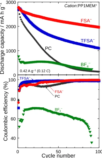
Figure 1(a) shows the dependence of the discharge (Li-extraction) capacity of a Si-alone
negative electrode on the cycle number in various ionic liquid electrolyte solutions. For comparison,
the result in an organic electrolyte (1 mol dm–3 LiTFSA/PC) is also shown. While the discharge
capacity of a Si electrode was as high as 3000 mA h g–1 in the first cycle in the PC-based electrolyte
solution, it rapidly decayed; the Si electrode showed poor cycling stability in the PC-based
electrolyte. The rapid capacity-fading resulted from disintegration of the active material layer due to
the large change in the volume of Si during Li-insertion and extraction [5]. The volumetric change
7
exposed surface of the electrode. This phenomenon led to a drop in Coulombic efficiency at around
the 30th cycle in the PC-based electrolyte, as shown in Figure 1(b). The initial discharge capacity of
a Si electrode was less than 800 mA h g–1 in the BF4–-based electrolyte solution. The cycle
performance of the electrode in the BF4–-based electrolyte was almost the same as that in the
PC-based electrolyte; the discharge capacity was less than 200 mA h g–1 at the 80th cycle in both
Figure 1 Dependence of (a) discharge capacity and (b) coulombic efficiency on cycle number for a Si electrode in 1 mol dm–3 LiX/PP1MEM-X. (X: FSA, TFSA, or BF4) For comparison, the performance in 1 mol dm–3 LiTFSA/PC is also shown.
0 1000 2000 3000
D
is
c
h
a
rg
e
c
a
p
a
c
it
y
/
m
A
h
g
− 1 40 60 80 100 0 50 100C
o
u
lo
m
b
ic
e
ff
ici
e
n
cy
(%
)
Cycle number
0.42 A g−1(0.12 C) FSA– TFSA– BF4– PC Cation:PP1MEM+ PC FSA– TFSA– BF4–8
electrolytes. Figure S2 shows the first charge-discharge profiles of a Si electrode in various
electrolytes. A potential plateau was observed at around 0.1 V vs. Li+/Li during the charge
(Li-insertion) process in all electrolytes, which corresponds to the Li–Si alloying reaction [4,5]. A
huge irreversible capacity was confirmed at around 0.2 V vs. Li+/Li on the charge curve in only the
BF4–-based electrolyte; an unfavorable reaction appears to occur on the Si electrode. The maximum
Coulombic efficiency of the Si electrode in the BF4–-based electrolyte was 70%, which was much
lower than that in the other electrolytes, as shown in Figure 1(b). Generally, an ideal surface film
formed on a negative electrode has very low electronic conductivity and high Li+ conductivity, which
suppresses continuous electrolyte decomposition. Therefore, the Coulombic efficiency increases after
formation of the surface film. However, the Si electrode maintained low efficiency in the BF4–-based
electrolyte. This result suggests that the BF4–-derived surface film did not function suitably as a
protective film to prevent continuous electrolyte decomposition.
On the other hand, in the FSA–- and TFSA–-based electrolytes, the Si negative electrode
exhibited a high initial discharge capacity of 2700 mA h g–1, which is almost the same as that in the
PC-based electrolyte. This result indicates that desolvation of Li+ from anions occurred more readily
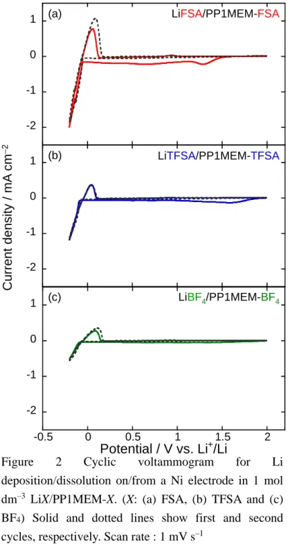
in the FSA–- and TFSA–-based electrolytes than in the BF4–-based electrolyte. To confirm this
assumption, cyclic voltammetry for a simple redox reaction of Li was performed using a Ni electrode
as a working electrode, as shown in Figure 2. A Ni working electrode was used because it does not
9
assigned to the deposition and dissolution of Li were observed at around –0.2 V and 0.1 V vs. Li+/Li,
respectively [21–23]. These peaks were large in the order FSA–- > TFSA–- > BF4–-based electrolytes,
which corresponds to the ionic association tendency of the Li salt [24]. This result indicates that the
desolvation of Li+ from the anion most easily occurs in the FSA–-based electrolyte, whereas the
Figure 2 Cyclic voltammogram for Li deposition/dissolution on/from a Ni electrode in 1 mol dm–3 LiX/PP1MEM-X. (X: (a) FSA, (b) TFSA and (c) BF4) Solid and dotted lines show first and second cycles, respectively. Scan rate : 1 mV s–1
-2 -1 0 1 -2 -1 0 1 -2 -1 0 1 -0.5 0 0.5 1 1.5 2 Potential / V vs. Li+/Li C u rr e n t d e n s it y / m A c m − 2
LiTFSA/PP1MEM-TFSA
LiBF4/PP1MEM-BF4
LiFSA/PP1MEM-FSA
(b)
(c) (a)
10
desolvation from BF4– does not occur as easily because of the stronger electrostatic interaction
between Li+ and BF4–. Therefore, the above assumption should be valid. In the first cycle, broad
reduction peaks were observed at ca. 1.4 V and 1.6 V vs. Li+/Li in the FSA–- and TFSA–-/ BF4–
-based electrolytes, respectively. Although the structure of the cation in all of the ionic liquids was
the same, they had different reduction potentials. This suggests that the anion species in the
electrolytes decomposed at each potential [25], and the surface film that consisted of the
decomposition products should affect the cycling performance of the Si electrode.
The initial Coulombic efficiency in the FSA–- and TFSA–-based electrolytes was about 70% at
the initial cycle and increased to almost 100% in the subsequent cycle. On the other hand, in the BF4–
-based electrolyte, the efficiency was lower in all cycles. This indicates that the surface films formed
in the FSA–- and TFSA–-based electrolytes have much better insulation properties. Therefore, the
FSA–- and TFSA–-derived surface films would act as a protective film to effectively prevent
continuous decomposition of the electrolytes.
As shown in Figure 1(a), the electrode retained a discharge capacity of 2000 mA h g–1 after
100 cycles in the FSA–-based electrolyte, which is twice that in the TFSA–-based electrolyte. It is
considered that cycling stability is attributed to the difference of composition of the surface film. The
surface film on Li electrode is composed of LiF, Li2O, Li2SO4, Li2S2O4, Li2NSO2CF3, LiyC2Fx,
LiSO2CF3 and others in TFSA-based electrolyte [26, 27]. On the other hand, the FSA-derived surface
11
surface of the electrodes are probably responsible for the passivation of the electrodes. However, it is
unclear that which component contributes to improve the cycling stability. Piper et al. investigated
the decomposition mechanism of the FSA– and TFSA– anions based on molecular dynamics
simulations [29]. They reported that the S-F bond in FSA– is broken preferentially, and F– is rapidly
released to form LiF, whereas LiF is not formed as readily in TFSA–. It is well known that LiF
improves the structural stability of the surface film [30]. Hence, the FSA–-derived surface film is
more stable and should contribute to better cycling performance.
Although the FSA–-based ionic liquid electrolyte improved the cycling performance of the Si
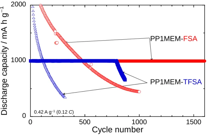
Figure 3 Variation in discharge capacity of a Si electrode in 1 mol dm–3 LiFSA/PP1MEM-FSA or LiTFSA/PP1MEM-TFSA versus number of cycles at a fixed Li-extraction level of 1000 mA h g–1. For comparison, the performance without capacity limitation is also plotted.
PP1MEM-FSA
PP1MEM-
TFSA
0.42 A g−1(0.12 C)0
1000
2000
0
500
1000
1500
D
is
c
h
a
rg
e
c
a
p
a
c
it
y
/
m
A
h
g
− 1Cycle number
12
electrode, gradual capacity-fading still occurred. We have demonstrated that the cycle
performancecan be remarkably enhanced by controlling Li-insertion/extraction, in moderation [10].A
charge-discharge cycling was performed with a Li-extraction capacity limitation of 1000 mA h g–1 in
the FSA–- and TFSA–-based electrolytes, as shown in Figure 3. In the TFSA–-based electrolyte, the
Si electrode maintained a reversible capacity of 1000 mA h g–1 until about the 800th cycle. On the
other hand, the Si electrode in the FSA–-based electrolyte exhibited better cycle performance with a
discharge capacity of 1000 mA h g–1 evenafter ca. 1600 cycles. Capacity limitation dramatically
improved the cycling stability, since the accumulation of severe stress was suppressed by moderation
of the change in the volume of Si. Notably, the cycle life of the electrode in the FSA–-based
electrolyte was twice as long as that in the TFSA–-based electrolyte. Hence, the superiority of the
FSA–-based electrolyte became clear when the capacity was limited.
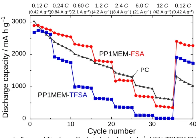
Rate performance is one of the most important characteristics of LIBs, especially when used in
an electric vehicle. Thus, the rate capability of a Si electrode in the ionic liquid electrolytes was
investigated, as shown in Figure 4. The electrodes showed reversible capacities of 700 mA h g–1, 100
mA h g–1, and 1000 mA h g–1 at a high current rate of 6 C (21 A g–1) in the FSA–-, TFSA–-, and
PC-based electrolytes, respectively. As shown in Table 1, the PC-based electrolyte exhibited the
highest ionic conductivity of 5.51 mS cm–1. In addition, the conductivity of the FSA–-based
electrolyte (2.06 mS cm–1) was three times that of the TFSA–-based electrolyte (0.66 mS cm–1). Since
13
and anion immensely influences on the viscosity and ionic conductivity of the ionic liquid. The
electrostatic interaction between Li+ and FSA– is weaker compared with it between Li+ and TFSA–.
In addition, it has been confirmed that FSA-based ionic liquid shows a lower viscosity than
TFSA-based one [31]. This is one of the reasons why FSA-based electrolyte has higher ionic
conductivity compared to TFSA-based electrolyte.
Electrolyte Conductivity / mS cm-1 Li-salt Solvent LiFSA PP1MEM-FSA 2.06 LiTFSA PP1MEM-TFSA 0.66 LiTFSA PC 5.51
Table 1 Ionic conductivity of electrolytes used in this study at 303 K.
Figure 4. Rate capability for a Si electrode in 1 mol dm–3 LiFSA/PP1MEM-FSA, LiTFSA/PP1MEM-TFSA, and LiTFSA/PC at various current rates from 0.12 C to 12 C.
0
1000
2000
3000
0
10
20
30
40
D
is
c
h
a
rg
e
c
a
p
a
c
it
y
/
m
A
h
g
− 1Cycle number
PP1MEM-
FSA
PP1MEM-
TFSA
PC
0.12 C 0.24 C 0.60 C 1.2 C 2.4 C 6.0 C 12 C 0.12 C (0.42 A g−1)(0.84 A g−1)(2.1 A g−1) (4.2 A g−1) (8.4 A g−1) (21 A g−1) (42 A g−1) (0.42 A g−1)14
Li-insertion into a Si negative electrode proceeds via several steps: (1) Li+ transport in the electrolyte
bulk, (2) desolvation of Li+ from ionic liquid anions or organic molecules, (3) Li+ transport in an
electric double layer and/or a solid electrolyte interphase, and (4) an alloying reaction of Si with Li
[32].anions or organic molecules, (3) Li+ transport in an electric double layer and/or a solid
electrolyte interphase, and (4) an alloying reaction of Si with Li [32]. Under a high rate of 6 C, Li+
transport, i.e. ionic conductivity in the electrolyte bulk, dominantly affects the rate capability.
Consequently, a good high-rate performance was achieved only in the FSA–-based electrolyte, even
though FSA– and TFSA– are based on the same amide. When the current rate was back to the initial
value of 0.12 C, the Si electrode showed a reversible capacity of 1200 mA h g–1 at the 36th cycle in
the PC-based electrolyte. In contrast, the discharge capacity of the electrode recovered to 2500 and
2000 mA h g–1 at the 36th cycle in the FSA–- and TFSA–-based electrolytes, respectively, which are
both higher than the capacity in the PC-based electrolyte. These results indicate that the Si electrode
was disintegrated in the PC-based electrolyte at a high current rate of 6 C, whereas deterioration of
the electrode was almost negligible in the FSA–- and TFSA–-based electrolytes. In addition, it is
considered that the discharge capacity-fading in the FSA–- and TFSA–-based electrolytes at 6 C is
mainly caused by limitation of the rate of Li+ diffusion in the electrolyte bulk.
4. Conclusions
15
performance of a Si-alone negative electrode for use in LIBs was investigated. The electrode showed
better cycle performance in FSA–- and TFSA–-based electrolytes than in a BF4–-based electrolyte; the
performance of the Si electrode is improved in some, but not all, ionic liquid electrolytes. The
electric conductivities of the surface films formed in the FSA–- and TFSA–-based electrolytes would
be lower than those in BF4–- and PC-based electrolytes. A Si-alone negative electrode also exhibited
excellent cycle performance with a discharge capacity of 1000 mA h g–1 beyond 1600 cycles in the
FSA–-based electrolyte under Li-extraction capacity limitation, which results from the structural
stability of the surface film with LiF. A high rate performance was achieved with a reversible
capacity of 700 mA h g–1 even at 6 C in the FSA–-based electrolyte due to the high conductivity of
the electrolyte. Consequently, the FSA–-based ionic liquid electrolyte is the most promising
electrolyte solution for next-generation LIBs with a Si-based negative electrode.
Acknowledgement
This work was partially supported by the Japan Society for the Promotion of Science (JSPS)
KAKENHI, Grant-in-Aid for Scientific Research B (Grant 24350094) and Grant-in-Aid for Young
Scientists B (Grant 15K21166).
References
16
[2] M. N. Obrovac, L. Christensen, Electrochem. Solid-State Lett. 7 (2004) A93.
[3] T. D. Hatchard, J. R. Dahn, J. Electrochem. Soc. 151 (2004) A838.
[4] M. N. Obrovac, L. J. Krause, J. Electrochem. Soc. 154 (2007) A103.
[5] M. K. Datta, P. N. Kumta, J. Power Sources 194 (2009) 1043.
[6] T. Zhang, J. Gao, L. J. Fu, L. C. Yang, Y. P. Wu and H. Q. Wu, J. Mater. Chem. 17 (2007) 1321.
[7] T. Zhang, L. J. Fu, H. Takeuchi, J. Suzuki, K. Sekine, T. Takamura, Y. P. Wu, J. Power Sources
159 (2006) 349.
[8] H. Usui, Y. Yamamoto, K. Yoshiyama, T. Itoh, H. Sakaguchi, J. Power Sources 196 (2011)
3911.
[9] H. Usui, T. Masuda, H. Sakaguchi, Chem. Lett. 41 (2012) 521.
[10] M. Shimizu, H. Usui, T. Suzumura, H. Sakaguchi, J. Phys. Chem. C 119 (2015) 2975.
[11] M. Shimizu, H. Usui, K. Matsumoto, T. Nokami, T. Itoh, H. Sakaguchi, J. Electrochem. Soc.
161 (2014) A1765.
[12] K. Hayamizu, S. Tsuzuki, S. Seki, J. Chem. Eng. Data 59 (2014) 1944.
[13] K. Hayamizu, S. Tsuzuki, S. Seki, K. Fujii, M. Suenaga, Y. Umebayashi, J. Chem. Phys. 133
(2010) 194505.
[14] H. Matsumoto, H. Sakaebe, K. Tatsumi, ECS Trans. 16 (2009) 59.
[15] Y. Umebayashi, T. Mitsugi, S. Fukuda, T. Fujimori, K. Fujii, R. Kanzaki, M. Takeuchi, S.
17
[16] Y. Umebayashi, S. Mori, K. Fujii, S. Tsuzuki, S. Seki, K. Hayamizu, S. Ishiguro, J. Phys. Chem.
B 114 (2010) 6513.
[17] K. Fujii, H. Hamano, H. Doi, X. Song, S. Tsuzuki, K. Hayamizu, S. Seki, Y. Kameda, K. Dokko,
M. Watanabe, Y. Umebayashi, J. Phys. Chem. C 117 (2013) 19314.
[18] T. Sugimoto, Y. Atsumi, M. Kikuta, E. Ishiko, M. Kono, M. Ishikawa, J. Power Sources 189
(2009) 802.
[19] T. Sugimoto, M. Kikuta, E. Ishiko, M. Kono, M. Ishikawa, J. Power Sources 183 (2008) 436.
[20] M. Yamagata, N. Nishigaki, S. Nishishita, Y. Matsui, T. Sugimoto, M. Kikuta, T. Higashizaki, M.
Kono, M. Ishikawa, Electrochim. Acta 110 (2013) 181.
[21] C. Liu, X. Ma, F. Xu, L. Zheng, H. Zhang, W. Feng, X. Huang, M. Armand, J. Nie, H. Chen, Z.
Zhou, Electrochim. Acta 149 (2014) 370.
[22] S. Fang, L. Yang, J. Wang, H. Zhang, K. Tachibana, K. Kamijima, J. Power Sources 191 (2009)
619.
[23] H. Matsumoto, H. Sakaebe, K. Tatsumi, M. Kikuta, E. Ishiko, M. Kono, J. Power Sources 160
(2006) 1308.
[24] P. Johansson, Phys. Chem. Chem. Phys. 9 (2007) 1493.
[25] P. C. Howlett, E. I. Izgorodina, M. Forsyth, D. R. MacFarlane, Z. Phys. Chem. 220 (2006) 1483.
[26] E. Markevich, R. Sharabi, V. Borgel, H. Gottlieb, G. Salitra, D. Aurbach, G. Semrau, M. A.
18
[27] S. Xiong, K. Xie, E. Blomberg, P. Jacobsson, A. Matic, J. Power Sources 252 (2014) 150.
[28] A. Budi, A. Basile, G. Opletal, A. F. Hollenkamp, A. S. Best, R. J. Rees, A. I. Bhatt, A. P.
O’Mullane, S. P. Russo, J. Phys. Chem. C 116 (2012) 19789.
[29] D. M. Piper, T. Evans, K. Leung, T. Watkins, J. Olson, S. C. Kim, S. S. Han, V. Bhat, K. H. Oh,
D. A. Buttry, S.-H. Lee, Nat. Commun. 6 (2015) 6230.
[30] K. Schroder, J. Alvarado, T. A. Yersak, J. Li, N. Dudney, L. J. Webb, Y. S. Meng, K. J.
Stevenson, Chem. Mater. 27 (2015) 5531.
[31] S. Tsuzuki, K. Hayamizu, S. Seki, J. Phys. Chem. B 114 (2010) 16329.
19 Figure captions
Figure 1 Dependence of (a) discharge capacity and (b) Coulombic efficiency on cycle number for a
Si electrode in 1 mol dm–3 LiX/PP1MEM-X. (X: FSA, TFSA, or BF
4) For comparison, the
performance in 1 mol dm–3 LiTFSA/PC is also shown.
Figure 2 Cyclic voltammogram for Li deposition/dissolution on/from a Ni electrode in 1 mol dm–3
LiX/PP1MEM-X. (X: (a) FSA, (b) TFSA and (c) BF4) Solid and dotted lines show the first and
second cycles, respectively. Scan rate : 1 mV s–1
Figure 3 Variation in discharge capacity of a Si electrode in 1 mol dm–3 LiFSA/PP1MEM-FSA or
LiTFSA/PP1MEM-TFSA versus number of cycles at a fixed Li-extraction level of 1000 mA h g–1.
For comparison, performance without capacity limitation is also plotted.
Figure 4 Rate capability for a Si electrode in 1 mol dm–3 LiFSA/PP1MEM-FSA,
LiTFSA/PP1MEM-TFSA, and LiTFSA/PC at various current rates from 0.12 C to 12 C.