第 54 卷 第 4 期
2019 年 8 月
JOURNAL OF SOUTHWEST JIAOTONG UNIVERSITY
Vol. 54 No. 4 Aug. 2019
ISSN -0258-2724 DOI:10.35741/issn.0258-2724.54.4.25
Research article
Electrical and Electronic Engineering
S
PEED
C
ONTROL OF
D
IRECT
C
URRENT
M
OTOR
U
SING
M
ECHANICAL
C
HARACTERISTICS
机械特性对直流电动机的速度控制
Hatem Fahd Frayyeh, Muayad A. Mukhlif, Abdulsalam M. Abbood, Settar S. Keream Electrical Engineering Department, Engineering College, University of Anbar, Ramadi, Al Anbar, Iraq, [email protected], [email protected],
[email protected], [email protected]
Abstract
A direct current (DC) motor is a very old machine, but the applications have become more important and developed in recent years. This article describes a new method of controlling the speed of a DC motor based on armature voltage control, armature resistance control and field excitation control with constant flux motors shunt and series field. The proposal allows improving the experimental result, and the simulation results have the same response with an expected error. This error is due to voltage drop and rotational losses. Armature voltage control is the best method and more economical; the cheapest method is armature resistance control, but this is wasteful and less versatile. The new method effectiveness evaluation has confirmed the calculation results.
Keywords: DC Machine, Drivers, Speed Control, Constant Flux Motor.
摘要 直流(DC)电机是一台非常古老的机器,但是近年来,其应用变得越来越重要和发展。 本文介绍了 一种基于电枢电压控制,电枢电阻控制和恒磁通分流和串联磁场励磁控制的直流电动机速度控制新方法。 该建议可以改善实验结果,并且模拟结果具有相同的响应,但存在预期的误差。 此错误是由于电压降和旋 转损耗引起的。 电枢电压控制是最好的方法,更经济; 最便宜的方法是电枢电阻控制,但这很浪费并且通 用性较低。 新方法的有效性评估已经确认了计算结果。 关键词: 直流电机,驱动器,速度控制,恒定磁通电动机。
I.
I
NTRODUCTIONDC motor control was developed rapidly. Theadvantages of DC motors, such as simple control, light weight, and small size have allowed themto be used in many modern devices, such asdrones,cars,games, and dolls. An efficient method for speed control of DC motors is pulse
width modulation (PWM). In PWM, data is sent to an ATmega16 microcontroller using a TV remote control andIR receiver. This controls the speed and direction of themotor. To estimate the speed, a punctured disk is located between the LED, and the photodiode acts as a sensor [1].
A robustness analysis and comparison of closed loop speed control using four-quadrant choppers was conductedfor different linear controllers of similar DC motors. The arrangements of the controller can be approximately classified as one of the following:
(i) Integer order PID controller (ii) Linear state space observer
(iii) Fractional order PID controller [2] Abio-inspired meta-heuristic soft-computing technique was used to enhance the performance of a PID controller, which controlled the speed of the DC motor. A PID controller was considered for an implemented second-order-system DC motor, and the evolutionary procedure built on Grey Wolf Optimizer was usedto improve the controller. In MATLAB/Simulink, the top set of PID parameters obtainedfrom the optimization wasapplied with a step input to the DC motor to provide the transient response conditions,such as settling time, rising time, steady state error, and maximum over shooting [3], [4].
A dependent switching function state with limited switching frequency was used and was validated experimentally in the situation for DC motor speed control driven by a buck-boost power converter. The buck-boost converter/DC-motor was worked as a combination, very beneficial in applied requests, and was displayed as a switched affine system in discrete time [5].
DC motor speed control was achieved by changing the duty cycle of the given gate signals of the power devices. An enclosed boost converter was favored for the gain of high voltage from the solar panel. Efficiency of the proposed structure was approved for various duty cycles with MATLAB/Simulink [6].
In this paper, the speed control of a shunt DC motor was done using armature voltage control, armature resistance control, and field excitation control. The experimental results and simulation results are compared for small and large machines.
When the machine is operating as motor, the shaft speed and output torque, and their effect on the drawn motor’s current, may be absorbed. The torque and emf equations are [7]:
Td = KIAФ (1)
EA = KenФ (2)
Ф is the useful resultant flux per pole (i.e., it is somewhat demagnetized due to the armature reaction). Td is the torque developed in motor, and
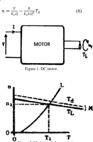
EA is the actual induced emf, as in Figure 1. Since
KVL, we get:
EA = V – (∑IR + Vb) (3)
where ∑IR is the whole voltage drop due to resistance of series (compensating, armature, series field, commutating wdgs, and a little added series resistance), and V is the applied voltage to the terminals of the DC motor. For simplicity, we can approximate this equation as:
EA = V – IAR (4)
R contains all series resistances have the same armature currant and assuming the drop voltage of brush was ignored. Refer to (4). Dividing by KeФ, and replacing (2), we find:
𝑛 =𝑉−𝐼𝐴𝑅
𝐾𝑒Ц (5)
The final equation was calculated primarily by the flux Ф, the applied voltage V, and therough reduction caused by the series drop voltage IAR
(which depends on load torque and current).
II.
R
ESEARCHM
ETHODSThe mechanical characteristic of a dc motor is the curve relating the motor’s two output variables, torque and speed; the curve shows how speed changes with load.
Substituting for IA from (2) into (5), we get [8]: 𝑛 =𝐾𝑉 𝑒Ц− 𝑅 𝐾𝑒𝑘Ц2𝑇𝑑 (6) Figure 1. DC motor.
For constant V and Ф, the relation (6) represents a straight line with negative slope (Figure 2).
The first term on the RHS gives the vertical intercept (no
-
load speed), and the coefficient of Td in the second term gives the slope.
The load torque TL is a little less than the developed torque Td as in (6), so that the relationship curves below the straight line.
The shape of the curve may be further modified due to changes in the flux Ф (which affects both slope and intercept) as the motor load changes; the flux changes with load when there is a series field, when the demagnetizing effect of armature reaction is not negligible. So that the straight line of Figure 2 is just a scaled representation of KVL]
9
[
.When the motor is driving a mechanical load, the torque and speed are found from the motor mechanical characteristic and the load characteristic (Figure 2); that is, the operating point (T1, n1) is found graphically. Figure 3 shows some typical characteristics of mechanical loads.
𝐴: 𝑇 ∝1
𝑛 (constant power; traction) 𝐵: 𝑇 = 𝑐𝑜𝑛𝑠𝑡𝑎𝑛𝑡 (traction; lifts; cranes) 𝐶: 𝑇 ∝ 𝑛 (machine tools)
𝐷: 𝑇 ∝ 𝑛2 (fans; centrifugal pumps)
𝐸: 𝑛 = 𝑐𝑜𝑛𝑠𝑡𝑎𝑛𝑡 (ac alternators) Figure 3. Speed with torque relationships.
III.
C
ONSTANT-F
LUXM
OTORSThe difference between shunt and separately excited motors is that the field of a shunt motor is fed from the same source as the armature, while the field of a separately excited motor is fed from a different source, possibly at a different voltage
.
In both cases, constant field voltage and resistance result in constant field current (If does not change with load), and hence constant main field flux. Permanent magnet motors also operate with a constant main field [10].
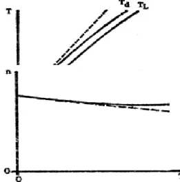
If the demagnetizing effect of armature reaction is neglected, the developed torque Td will
be directly proportional to the armature current Ia as in (2), so that the two variables are related by the straight line shown dotted in Figure 4. Armature reaction may reduce the flux Ф, and hence reduce Td, so that the actual relationship between Td and TL is curved slightly below the straight line
.
The load torque TL is less than the developed torque Td due to rotational losses, see (6) so that the TL curve is slightly below the Td curve (Figure 4). The relationship between torque and current is sometimes called the torque characteristic of the motor [11].For constant
-
flux motors, the mechanical characteristic is a straight line with a slight negative slope as in (3) and Figure 5. Armature reaction may reduce useful flux and hence increase the speed, so that the mechanical characteristic curves slightly above the straight line.
This upward curvature may lead to instability. It is avoided by designing the motor to have no demagnetizing armature reaction (by the use of interlopes), and by adding a weak series field to compensate for the reduction in flux (stabilized shunt motor).
The reduction in speed with load is very small for constant
-
flux motors.
The mechanical characteristic is said to be hard, and the motors operate in an essentially constant speed mode.
IV.
S
PEEDC
ONTROL OFDC
M
OTOR According to (5) the rotational speed can be controlled by the series resistance, main flux, and the applied voltage; these parameters can be adjusted automatically or manually. While the armature current gives the idea in the equation.The mechanical characteristic matches to a specific setting of the series resistance, field control resistor, and applied voltage. If the settings of the above parameters are changed, the operation of the machine will shift from curve to another curve. So, the operating point (T, n) will moved from one curve to another curve by varying the setting the control parameters (Figure 6) [12]. By automatic regulators the speed can be kept approximately constant, the regulator can be sensing the shaft speed and correct one of the control parameters to get the desired value.
Figure 4. Torque characteristic.
A. Speed Control by Armature Voltage Control
The torque
-
speed characteristic of constant flux (permanent-
magnet, shunt, and separately) exited motors as in (6) describes as a straight line (Figure 5). The first term on the right-hand side represent the intercept with n-axis, and the factor of developed torque Td is the second term represent the slope of the line, which is negative value.In separately
-
excited and permanent-
magnet motors, the voltage applied to the motor can be changed with the remaining constant flux. Different applied voltages will give different intercepts, and the lines will appear as parallel lines (same slope) as in Figure 7. In this figure, the rated voltage denoted Vr. When the applied voltage is reduced, the mechanical characteristic will be shifted down. For series motor the shifts occur downward also (Figure 8); the series motorapproaches constant
-
flux operation when the loads are heavy, and the curves approaches to parallel straight lines as seen in Figure 7 [13].
The voltage divider is using as a simplest process to obtain a variable dc voltage, this technique is unusable and wasteful; it is used for testing only
.
In advance applications, a solid
-
state controlled rectifier was used as a variable dc voltage, while the field voltage will be getting from an uncontrolled rectifier. The firing angle of the controlled rectifier can be adjusted by hand, then in practice it is changed automatically using an armature current signal or speed signal, or together for optimum control [14].B. Armature Resistance Control
For a given current, and hence given load torque, adding an external resistance in series with the armature (Figure 9), decreases the emf and hence rotational speed. Increasing the magnitude of resistance rises the slope of the mechanical characteristic see (6). The hard characteristic become softer for constant
-
flux motor with increasing resistance as in Figure 9a, while, the intercept with n –axis still unchanged.The armature resistance control may be also applied with series motors see curves as shown in
Figure 7. Mechanical characteristic of shunt motor.
Figure 8. Mechanical characteristic of series motor.
(a) (b)
Figure 6. Mechanical characteristics of DC motor: (a) stable operation, (b) unstable operation.
(a) Constant-flux
(b) Series motor
Figure 9b; at heavy loads the field of DC motor will saturated and operated like a constant
-
flux motors with slope growing when the resistance is enlarged. Armature resistance control is simple to use with small motors and low-cost, while it is wastes energy and unusable with large motors. C. Field ControlThe field control can be used for speed control with separately and shunt excited motors. With rated voltage and with no field control resistance FCR in the field circuit, the mechanical
-characteristic of the motor will appear as a constant flux; that is called the base case (Figure10).
When adding FCR in series with the field circuit resistance the total resistance will increased, the field current, and hence the main field, will be decreased, so according to (5) or (6) the rotational speed will increase. We will obtain a group of curves above the base case (Figure 10). When the field resistance is higher, the intercept is higher and the greater the slope [15]. The magnetic flux cannot be reduced indefinitely because of the speed will be very high and may be damage the motor, also, may be lead to instability [16].
V.
T
HER
ESULTSThe experimental results for the shunt DC motor was attempt. Table 1 explains the specification of the shunt wound DC machine.
Table 1. Parameters of DC machine Vr Ia If n Ip Ra Rf Power 205 (V) 2 A 0.33 A 2000 rpm 54 16Ω 482.8 Ω 0.3 Kw
For armature voltage control, the applied voltages were chosen in three deferent magnitude (207.5 V, 150.7 V, 100.7 V). Table 2 represents the experimental results when the armature voltage was 207.5 V, the other results only plotted for compare.
Figure 11 represents the mechanical characteristics of the shunt wound DC machine when armature voltage was changed in three magnitudes.
Table 2.
Experimental reading of armature voltage control
T (N.m) n (rpm) Vt (V) Ia (A) If (A) 0 1890 205.5 0.17 0.33 0.1 1800 205.8 0.3 0.33 0.23 1720 205.2 0.43 0.33 0.39 1610 205.4 0.6 0.33 0.53 1530 205.7 0.73 0.33 0.73 1400 205 0.92 0.33 0.86 1320 205.2 1.07 0.33 0.88 1300 20.5.6 1.09 0.33 1.09 1170 205.1 1.3 0.33 1.36 990 205.7 1.59 0.33 1.84 720 205 2.02 0.33
There is deference between the simulation results and the experimental results because of the rotational losses.
Table 3 explains the armature resistance control with R = 55Ω; the external resistance was adding in series with armature resistance to increase its values. The magnitude was (0Ω, 55Ω, 150Ω) on three stages as appear in Figure 12.
Table 3.
Experimental reading of armature resistance control
T (N.m) n (rpm) Vt (V) Ia (A) If (A) 0 2000 207.5 0.21 0.33 0.27 1980 207.4 0.44 0.33 0.37 1970 207.5 0.55 0.33 0.45 1960 207.8 0.63 0.33 0.62 1950 207.6 0.8 0.33 0.77 1940 207.3 0.96 0.33 0.93 1930 207.2 1.15 0.33 1.11 1910 207.5 1.33 0.33 1.41 1890 207.5 1.67 0.33 1.57 1880 207.5 1.88 0.33 1.67 1870 207.5 2.03 0.33 Figure 10. Field control.
Figure 11. Simulation and experimental results of voltage control.
Figure 12 illustrates the mechanical characteristic of the shunt wound DC machine in
simulation and experimental results for adding resistance in series with armature resistance. The differences between the readings in practice there are additional losses such as rotational losses.
Table 4 illustrates the reading of experimental results of field control to shunt wound DC machine for deferent values of field current (0.19A, 0.25A, 0.33A) as shown in Figure 13.
Table 4.
Experimental reading of field control
T (N.m) n (rpm) Vt (V) Ia (A) If (A) 0 1460 150.8 0.19 0.33 0.15 1450 150.2 0.27 0.33 0.21 1440 150.6 0.34 0.33 0.35 1430 150.1 0.49 0.33 0.48 1400 150 0.63 0.33 0.6 1390 150.2 0.73 0.33 0.79 1380 150.6 0.96 0.33 0.94 1360 150.4 1.1 0.33 1.34 1330 150.3 1.52 0.33 1.54 1320 150.7 1.7 0.33 1.96 1280 150.8 2.2 0.33
VI.
D
ISCUSSION ANDF
INDINGSArmature voltage control provides the best method of speed control of DC motors; indeed, it is the main reason for the continuing existence of large DC machines. The speed may be controlled from zero to maximum safe speed in either forward or reverse direction. The control can be manual, or automatic with speed or current sensors. The constant speed feature of constant-flux motors is retained, giving adjustable speed drives.
Armature resistance control is cheaper than armature voltage control, but it is wasteful and less versatile. As the armature resistance increases, the mechanical characteristic becomes softer, and the motor operates at variable speed. This type of control is sometimes used with relatively small series or permanent magnet motors.
Shunt field control is also relatively cheap; however, it is wasteful and does not compete with armature voltage control as it increases speed from the base value and cannot reduce speed to zero. The mechanical characteristic becomes softer as the field resistance is increased, and there is an upper limit on the speed that can be reached, usually around 2:1 (i.e. twice the base speed).
In some applications, particularly traction, both armature voltage and field control are used. Figure 14 shows how armature voltage control is used up to base speed to maintain the torque constant; above base speed, field control is used to maintain the output power constant (2πnT).
Small DC motors with fixed excitation are often used in automatic control systems.
Figure 14. Stability of DC motor. Figure 12. Simulation and experimental results of
armature resistance control.
Figure 13. Simulation and experimental results of field control.
They are designed to have linear mechanical characteristics with accurate voltage control down to stall (standstill), as shown in Figure 15 from the simulation and experimental results.
R
EFERENCES[1] AGUNG, I.R., HUDA, S. and WIJAYA, I.
A. (2014) Speed control for DC motor
with pulse width modulation (PWM)
method using infrared remote control
based on ATmega16 microcontroller.
Proceedings
of
the
International
Conference on Smart Green Technology
in Electrical and Information Systems, pp.
108-112.
DOI: 10.1109/ICSGTEIS.2014.7038740
[2] DAS, C.K. and SWAIN, S.K. (2017)
Closed loop speed control of chopper fed
DC motor for industrial drive application.
Proceedings
of
the
International
Conference on Power and Embedded
Drive
Control,
pp.
478-483.
DOI: 10.1109/ICPEDC.2017.8081137
[3] DAS, K.R., DAS, D., and DAS, J. (2015)
Optimal tuning of PID controller using
GWO algorithm for speed control in DC
motor. Proceedings of the International
Conference
on
Soft
Computing
Techniques and Implementations, pp.
108-112.
DOI: 10.1109/ICSCTI.2015.7489575
[4] SALEH, M.S., MOHAMMED, K.G.,
AL-SAGAR, Z.S., and SAMEEN, A.Z.
(2018) Design and Implementation of
PLC-Based Monitoring and Sequence
Controller System.
Journal of Advanced
Research in Dynamical and Control
Systems,
10(02),
pp.
2281-2289.
https://www.researchgate.net/profile/Aws
_Zuhair2/publication/329265377_Design
_and_Implementation_of_PLC-Based_Monitoring_and_Sequence_Contr
oller_System/links/5bff5282a6fdcc1b8d4
a00ca/Design-and-Implementation-of-
PLC-Based-Monitoring-and-Sequence-Controller-System.pdf
[5] KHALAF, O.I., ABDULSAHIB, G.M.,
and SADIK, M. (2018) A Modified
Algorithm for Improving Lifetime WSN.
Journal of Engineering and Applied
Sciences,
13,
pp.
9277-9282.
https://scholar.google.com/scholar?hl=ar
&as_sdt=0%2C5&q=KHALAF%2C+O.I
.%2C+ABDULSAHIB%2C+G.M.%2C+
and+SADIK%2C+M.+%282018%29+A
+Modified+Algorithm+for+Improving+L
ifetime+WSN.+&btnG=
[6] KARTHIKA,
P.,
BASHA,
M.A.,
AYYAPPAN, P., SIDHARTHAN, C., and
RAJAKUMAR, V. (2016) PV based
speed control of DC motor using
interleaved boost converter with SiC
MOSFET and fuzzy logic controller.
Proceedings
of
the
International
Conference on Communication and
Signal
Processing,
pp.
1826-1830.
DOI: 10.1109/ICCSP.2016.7754485
[7] KUMAR, S.B., ALI, M.H., and SINHA,
A. (2014) Design and Simulation of
Speed Control of DC Motor by Artificial
Neural Network Technique. International
Journal of Scientific and Research
Publications,
4(7).
pp(255-258)
https://www.researchgate.net/profile/Sadi
k_Batcha_M/publication/324829649_Hol
istic_Approach_of_Research_Work_PDF
_from_psuedu/links/5b3233944585150d2
3d55a1f/Holistic-Approach-of-Research-Work-PDF-from-psuedu.pdf#page=256
[8] MOHAMMED,
K.G.
(2006)
Experimental Study for Enhancement the
Three-Phase Induction Motor Using
Microprocessor
TMS320F.
ARPN
Journal of Engineering and Applied
Sciences,
13(17),
pp.
1-5.
https://scholar.google.com/scholar?hl=ar
&as_sdt=0%2C5&q=MOHAMMED%2
C+K.G.+%282006%29+Experimental+St
udy+for+Enhancement+the+Three-Phase+Induction+Motor+Using+Micropr
ocessor+TMS320F.+ARPN+&btnG=
[9] KEREAM, S.S., ABDALLA, A.N., and
DAUD,
M.R.B.
(2017)
Nonlinear
Dynamic Inverse Controller Based in
Field Oriented with SVPWM Current
Control. Pertanika Journal of Science &
Technology,
25(S),
pp.
37-44.
https://scholar.google.com/scholar?hl=ar
&as_sdt=0%2C5&q=KEREAM%2C+S.S
.%2C+ABDALLA%2C+A.N.%2C+and+
DAUD%2C+M.R.B.+%282017%29+No
nlinear+Dynamic+Inverse+Controller+B
ased+in+Field+Oriented+with+SVPWM
+Current+Control.&btnG=
[10] MEHTA, N.D., HAQUE, A.M., and
MAKWANA, M.V. (2016) Controllers
for Speed Control of DC Motor Drives:
Modeling
&
Simulations.
https://scholar.google.com/scholar?hl=ar
&as_sdt=0%2C5&q=MEHTA%2C+N.D.
%2C+HAQUE%2C+A.M.%2C+and+M
AKWANA%2C+M.V.+%282016%29+C
ontrollers+for+Speed+Control+of+DC+
Motor+Drives%3A+Modeling+%26+Sim
ulations.&btnG=
[11] KEREAM, S.S., ABDALLA, A.N.,
DAUD, M.R.B., and KOH, J. (2018)
Dynamic Inverse Controller with Matrix
Converter Drive Feed Three Phase
Induction Motor.
MATEC
Web of
Conferences,
225,
p.
2502022.
https://doi.org/10.1051/matecconf/20182
2502022
[12] KEREAM, S.S., ABDALLA, A.N.,
FRAYYEH, H.F., and DAUD, M.R.B.
(2016) Three Phase Induction Motor
Torque Ripple Minimization Based on a
Novel
Nonlinear
Dynamic
Inverse
Controller.
Proceedings of the National
Conference for Postgraduate Research,
pp.
321-329.
https://www.researchgate.net/profile/Hate
m_Frayyeh/publication/328643380_Thre
e_Phase_Induction_Motor_Torque_Rippl
e_Minimization_Based_On_a_Novel_No
nlinear_Dynamic_Inverse_Controller/link
s/5bda233892851c6b279ca129/Three-
Phase-Induction-Motor-Torque-Ripple-
Minimization-Based-On-a-Novel-
Nonlinear-Dynamic-Inverse-Controller.pdf
[13] KEREAM, S.S., MOHAMMED, K.G.,
and IBRAHIM, M.S. (2018) Analysis
Study in Principles of Operation of DC
Machine.
Journal of Advanced Research
in Dynamical and Control Systems,
10(02),
pp.
2323-2329.
https://scholar.google.com/scholar?hl=ar
&as_sdt=0%2C5&q=KEREAM%2C+S.S
.%2C+MOHAMMED%2C+K.G.%2C+a
nd+IBRAHIM%2C+M.S.+%282018%29
+Analysis+Study+in+Principles+of+Op
eration+of+DC+Machine.&btnG=
[14] NAGARAJAN,
D.R.,
SATHISHKUMAR,
S.,
BALASUBRAMANI, K., BOOBALAN,
C., NAVEEN, S., and SRIDHAR, N.
(2016) Chopper fed speed control of DC
motor using PI controller. IOSR-Journal
of Electrical and Electronics Engineering,
11,
pp.
65-69.
https://scholar.google.com/scholar?hl=ar
&as_sdt=0%2C5&q=NAGARAJAN%2C
+D.R.%2C+SATHISHKUMAR%2C+S.
%2C+BALASUBRAMANI%2C+K.%2C
+BOOBALAN%2C+C.%2C+NAVEEN
%2C+S.%2C+and+SRIDHAR%2C+N.+
%282016%29+Chopper+fed+speed+cont
rol+of+DC+motor+using+PI+controller.+
&btnG=
[15] SALMAN, A.D., KHALAF, O.I., and
ABDULSAHIB,
G.M.
(2019)
An
adaptive intelligent alarm system for
wireless sensor network. Indonesian
Journal of Electrical Engineering and
Computer Science, 15(1), pp. 142-147.
DOI: 10.11591/ijeecs.v15.i1.pp142-147