JIIA NIF-001-2010
CoaXPress Standard
CoaXPress 規格書
Enacted on Dec. 6, 2010
2010 年 12 月 6 日 制定
First edition
The Standardization Committee ― CoaXPressWorking Group
Japan Industrial Imaging Association
標準化委員会 ― CoaXPress 分科会
This document is provided “as it is” with this current version.
None of JIIA, its members including Liaison members, the subsidiary companies of its members, or the affiliates of its members are liable, whether express or implied, for any kinds of warranties of merchantability, fitness for a particular purpose, and non-infringement of third party property rights. この書面は“現状のまま”の状態で提供されます。
JIIA,または JIIA のリエゾン会員を含む会員,会員の子会社もしくは会員の関係会社のいずれも,この書面の内 容に関して,商品性,特定の目的への適合性,非侵害の保証を含め,いかなる保証も,明示たると黙示たるとを 問わず一切行いません。
JIIA, its members including Liaison members, the subsidiary companies of its members, or the affiliates of its members are exempted from taking responsibility and held harmless under the applicable law, whether express or implied, for any kinds of damages or losses arising from a course of usage of this document, including but not limited to passive damages, derivative damages, and incidental damages. This is applied even when any of JIIA, its members including Liaison members, the subsidiary companies of its members, or the affiliates of its members was informed of the possibilities of damages in advance.
JIIA,または JIIA のリエゾン会員を含む会員,会員の子会社もしくは会員の関連会社のいずれも,この書面の使 用,または使用不能から生ずるいかなる損害(逸失利益,及びその他の派生的,または付随的な損害を含むが, これらに限定されない全ての損害を言います。)について,適用法で認められる限り,一切の責任を負わないも のとします。 たとえ JIIA,または JIIA のリエゾン会員を含む会員,会員の子会社もしくは会員の関連会社がかかわる損害の 可能性について知らされていた場合でも同様です。
JIIA, its members including Liaison members, the subsidiary companies of its members, or the affiliates of its members are exempted from taking responsibility and held harmless for any litigation, including but not limited to on defending, on cooperating, and on compensating, and infringement of intellectual property rights with third party, incurred by the usage of this document.
JIIA,または JIIA のリエゾン会員を含む会員,会員の子会社もしくは会員の関連会社のいずれも,この書面に起 因して第三者との間に生じた,または生じうる知的財産権に関する紛争について,防御,協力,または補償する 責任を負わないものとします。
The Japanese text is a translation from the original English. In the event of doubt about the intended meaning, the English version is definitive.
和文は英語による原文の翻訳です。意図された意味に疑義が生じた場合は,英語版を正文とします。
©2010 Japan Industrial Imaging Association ©2010 一般社団法人 日本インダストリアルイメージング協会
Table of Contents 目次
Foreword (まえがき)...xiii
1 Scope (適用範囲)... 1
2 Normative Reference (引用規格) ... 1
3 References and Definitions of Terms (参照と用語の定義)... 2
3.1 Definition of Terms (用語の定義) ... 2
3.2 Abbreviations (略称) ... 3
3.3 Conventions (慣例) ... 3
4 Introduction to CoaXPress (CoaXPress の序説) ... 4
4.1 Overview (概要) ... 4
4.2 Use of Coax Cable (同軸ケーブルの採用) ... 6
4.3 CoaXPress Speeds (CoaXPress の各スピード) ... 7
4.4 Link Aggregation (リンクアグリゲーション) ... 8
4.5 Maximum Cable Length (最大ケーブル長)... 9
4.6 Data Communication (データ通信) ... 9
4.7 Trigger Accuracy (トリガ精度)... 9
4.8 Power over Cable (ケーブルを通じての電源重畳) ... 10
4.9 Data Integrity (データの整合性) ... 10
4.10 Plug and Play (プラグアンドプレイ) ... 11
4.10.1 General (一般情報) ... 11
4.10.2 GenICam (GenICam)... 12
4.11 Labeling and Use of the CoaXPress Logos (各 CoaXPress ロゴのラベリングと使用)... 12
4.11.1 Official CoaXPress Logo (CoaXPress の公式ロゴ)... 12
4.11.2 CoaXPress Logo Varieties (CoaXPress ロゴの種類)... 13
4.11.3 Product Labeling (製品へのラベリング) ... 14
4.11.4 Product Feature Bar (製品への機能表示)... 15
5 Cable and Connector Specification (ケーブルとコネクタの仕様)... 16
5.1 Introduction (序文) ... 16 5.2 Connectors (コネクタ) ... 16 5.2.1 Single Connectors (シングルコネクタ) ... 16 5.2.2 Multi-Connectors (マルチコネクタ) ... 17 5.2.3 Couplers (カプラ)... 17 5.2.4 Contact Material (接点部材質) ... 17
5.3 Multiple Cables for Link Aggregation (リンクアグリケーション用マルチケーブル) ... 17
5.4 Connector Indicator Lamps (コネクタの表示ランプ) ... 18
6 Electrical Specification (電気的仕様)... 21
6.2 Top Level Overview (全体構成) ... 21
6.3 Capacitor Cd (コンデンサ Cd)... 23
6.4 Termination (終端) ... 23
6.5 Impedance Zp (インピーダンス Zp)... 24
6.6 High Speed Link (ハイスピードリンク)... 25
6.7 Low Speed Link (ロースピードリンク)... 26
6.8 Return Loss at Connectors (CXP コネクタジャックのリターンロス) ... 29
7 Power over CoaXPress: PoCXP (電源重畳型 CoaXPress: PoCXP) ... 31
7.1 Overview (概要) ... 31
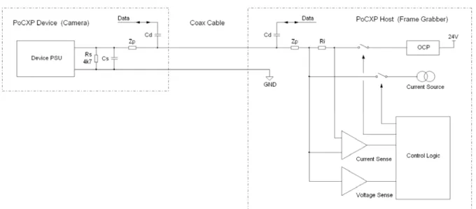
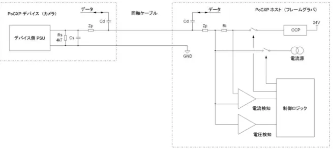
7.2 Simplified Example Block Diagram (簡略化されたブロックダイアグラムの例) ... 32
7.3 Device Requirements (デバイス側条件) ... 33
7.3.1 General Requirements (一般条件) ... 33
7.3.2 Operating Requirements (動作条件) ... 34
7.3.2.1 Voltage (電圧)... 34
7.3.2.2 Power (消費電力)... 34
7.3.3 Support for CoaXPress Detection (CoaXPress 自動認識対応) ... 35
7.3.3.1 Input Resistance (入力部の抵抗) ... 35
7.3.3.2 Input Capacitance (入力部の静電容量) ... 35
7.3.3.3 Minimum Load Power (最小負荷電力) ... 35
7.3.4 Devices Over 13W (消費電力 13W 以上のデバイスについて)... 36
7.3.5 Additional Power Connectors (追加電源コネクタ) ... 36
7.3.5.1 Non-PoCXP CoaXPress Devices (PoCXP 非対応の CoaXPress デバイス) ... 36
7.3.5.2 Dual Power CoaXPress Devices (デュアル電源の CoaXPress デバイス)... 37
7.4 Host Requirements (ホスト側条件) ... 37
7.4.1 General Requirements (一般条件) ... 37
7.4.2 Operating Requirements (動作条件) ... 38
7.4.2.1 Voltage (電圧)... 38
7.4.2.2 Power (消費電力)... 38
7.4.3 Over-Current Protection: OCP (過電流保護回路: OCP) ... 38
7.4.4 Support for CoaXPress Detection (CoaXPress 検知対応について) ... 39
7.4.5 Additional Features (その他の機能) ... 42
8 Link Protocol (リンクプロトコル) ... 43
8.1 Overview (概要) ... 43
8.2 Transport Layer (トランスポートレイヤ) ... 45
8.2.1 Packet Transmission Format (パケット伝送フォーマット)... 45
8.2.2 Bit Error Handling (ビットエラーの取り扱い) ... 46
8.2.2.1 Duplicated Characters (キャラクタの重複) ... 46
8.2.2.2 CRC (CRC)... 47
8.2.3 Packet Types (各パケットタイプ) ... 49
8.2.5 Idle Transmission (アイドルの伝送) ... 53
8.2.5.1 Idle Usage (アイドルの使用) ... 54
8.2.5.2 Stretching Packet Transmission with IDLE (IDLE を用いたパケット伝送の伸張) ... 55
8.3 I/O Channel (I/O チャンネル) ... 55
8.3.1 GPIO (GPIO) ... 56
8.3.2 Trigger (トリガ) ... 56
8.3.2.1 Low Speed Link Trigger (ロースピードリンクのトリガ)... 57
8.3.2.2 High Speed Link Trigger (ハイスピードリンクのトリガ)... 61
8.3.3 I/O Acknowledgments (I/O の ACK) ... 61
8.4 Data Packet Definition (データパケットの定義) ... 64
8.5 Stream Data Packet (ストリームデータパケット) ... 65
8.5.1 Stream Data Packet Format (ストリームデータパケットのフォーマット) ... 67
8.5.2 Packet Size (パケットサイズ)... 68
8.5.3 Packet Order (パケットの順序)... 69
8.5.4 Combining Multiple Streams (マルチプルストリームの結合) ... 69
8.5.5 Packet Transfer over Multiple Links (マルチプルリンク間でのパケット伝送) ... 70
8.6 Control Channel (コントロールチャンネル) ... 71
8.6.1 Control Transactions (コントロールトランザクション) ... 72
8.6.2 Control Command Message Format (コントロールコマンドのメッセージフォーマット) ... 76
8.6.3 Acknowledgment Message Format (ACK メッセージフォーマット) ... 78
8.6.4 Control Transaction Block Size (コントロールトランザクションのブロックサイズ) ... 80
8.7 Link Test (リンクテスト) ... 80
8.7.1 Link Test Methodology (リンクテスト方法) ... 80
8.7.2 Link Test Data Packet Payload Format (リンクテストのデータパケットぺイロードフォーマット)... 81
8.7.3 Host to Device Link Test (ホストからデバイスへのリンクテスト) ... 82
8.7.4 Device to Host Link Test (デバイスからホストへのリンクテスト) ... 83
9 Data Streams (データストリーム)... 85 9.1 Overview (概要) ... 85 9.2 Stream Format (ストリームフォーマット) ... 85 9.3 Stream ID (ストリーム ID)... 86 9.4 Image Streams (画像ストリーム)... 86 9.4.1 Pixel Types (ピクセルタイプ) ... 87 9.4.1.1 Pixel Formats (ピクセルフォーマット) ... 87
9.4.1.2 Data Width / Packing (データ幅/格納) ... 89
9.4.1.3 Mono Format (Mono(白黒)フォーマット) ... 90
9.4.1.4 Planar Format (Planar フォーマット) ... 90
9.4.1.5 Bayer Format (ベイヤーフォーマット) ... 92
9.4.1.6 RGB Format (RGB フォーマット) ... 93
9.4.1.7 RGBA Format (RGBA フォーマット)... 93
9.4.1.9 YCbCr601 Format (YCbCr601 フォーマット)... 95
9.4.1.10 YCbCr709 Format (YCbCr709 フォーマット)... 96
9.4.2 Pixel Packing (ピクセルの格納) ... 97
9.4.3 Multiple Images (複数の画像) ... 99
9.4.4 Image Scan Format (画像スキャンフォーマット) ... 100
9.4.5 Tap Concept (タップ概要) ... 100
9.4.6 Rectangular Image Stream (矩形画像ストリーム) ... 104
9.4.6.1 Transmission Rules (伝送規則)... 104
9.4.6.2 Rectangular Image Header (矩形画像のヘッダ) ... 106
9.4.6.3 Rectangular Image Line Marker (矩形画像ラインマーカ)... 110
9.4.7 Arbitrary Image Stream (任意形状画像ストリーム) ... 110
9.4.7.1 Transmission Rules (伝送規則)... 110
9.4.7.2 Arbitrary Image Header (任意形状画像のヘッダ) ... 113
9.4.7.3 Arbitrary Line Marker (任意形状画像のラインマーカ)... 115
10 Device Setup (デバイスのセットアップ) ... 116
10.1 Device Discovery (デバイスのディスカバリ処理) ... 116
10.1.1 Link State (リンクステート)... 117
10.1.2 Match Device and Host Bit Rates (デバイスとホストのビットレートマッチング)... 117
10.1.3 Discover Devices and Connection Topology (デバイスのディスカバリ処理と接続トポロジ)... 120
10.1.4 Negotiate Maximum Packet Data Sizes (最大パケットサイズのネゴシエーション)... 123
10.1.5 Detection of Loss of Lock (ロック外れの検出)... 125
10.2 Setting the Operating Bit Rate (動作ビットレートの設定) ... 125
10.2.1 Choosing the Bit Rate (ビットレートの選択) ... 125
10.2.2 Setting the Bit Rate (ビットレート設定) ... 126
10.3 GenICam and XML Files (GenICam と XML ファイル) ... 128
10.3.1 Use Case of Device (デバイスのユースケース) ... 129
10.3.2 Mandatory Features to Support the Use Case (ユースケースをサポートするための必須機能) .. 129
10.3.2.1 Width ... 130 10.3.2.2 Height ... 130 10.3.2.3 AcquisitionMode ... 130 10.3.2.4 AcquisitionStart... 131 10.3.2.5 AcquisitionStop ... 131 10.3.2.6 PixelFormat... 131 10.3.2.7 TapGeometry... 131 10.3.2.8 Image1StreamID... 132 10.3.2.9 Image2StreamID... 132 10.3.3 XML File Location (XML ファイルのロケーション)... 132
10.3.3.1 URL Format – Non-Volatile Memory (URL フォーマット - 不揮発性メモリ) ... 133
10.3.3.2 URL Format – Vendor Website (URL フォーマット - メーカーウェブサイト)... 134
10.4.1 Standard ... 139 10.4.2 Revision... 139 10.4.3 XmlManifestSize ... 139 10.4.4 XmlManifestSelector... 139 10.4.5 XmlVersion[XmlManifestSelector]... 140 10.4.6 XmlSchemaVersion[XmlManifestSelector]... 141 10.4.7 XmlUrlAddress[XmlManifestSelector] ... 141 10.4.8 IidcPointer... 141 10.4.9 DeviceVendorName... 142 10.4.10 DeviceModelName... 142 10.4.11 DeviceManufacturerInfo... 142 10.4.12 DeviceVersion... 142 10.4.13 DeviceFirmwareVersion... 142 10.4.14 DeviceID ... 142 10.4.15 DeviceUserID... 142 10.4.16 LinkReset... 143 10.4.17 DeviceLinkID... 144 10.4.18 MasterHostLinkID ... 144 10.4.19 ControlPacketDataSize... 144 10.4.20 StreamPacketDataSize... 145 10.4.21 LinkConfig... 145 10.4.22 TestMode... 146 10.4.23 TestErrorCountSelector ... 147 10.4.24 TestErrorCount[TestErrorCountSelector]... 147
11 Transport Layer API (トランスポートレイヤ API)... 148
11.1 Overview and standardization (概要と標準化)... 148
11.2 Use Case of Host(ホストのユースケース) ... 149
11.3 Software architecture (ソフトウェア・アーキテクチャ) ... 150
11.3.1 Software Interface (ソフトウェアインターフェース)... 153
11.3.1.1 Overview (概要) ... 153
11.3.1.2 Installation (インストール方法) ... 153
11.3.1.3 Requirements and Recommendations (必須および推奨要件) ... 153
11.3.1.4 Implementation Recommendations (推奨される実装方法)... 154
11.3.2 Configure a Device (デバイスコンフィグレーション) ... 156
11.4 Common SFNC and CoaXPress SFNC (共通 SFNC と CoaXPress SFNC) ... 158
11.4.1 Common SFNC (共通 SFNC) ... 158
11.4.2 CoaXPress SFNC (CoaXPress SFNC)... 158
Annex A : Detailed Cable Specification (附属書 A: ケーブル仕様の詳細)... 159
A.1 Introduction (序文) ... 159
A.3 Return Loss of Cables (ケーブルのリターンロス)... 159
A.4 Cable Length Limitations (ケーブル長上限)... 160
A.4.1 Power Supply Voltage Drop (電源電圧降下) ... 160
A.4.2 High Speed Link Requirements (ハイスピードリンクの要求仕様) ... 161
A.4.3 Low Speed Link Requirements (ロースピードリンクの条件)... 161
A.5 Cable Current Capacity (ケーブルの電流容量) ... 162
A.6 Cable Attenuation (ケーブルの減衰量) ... 162
Annex B : Chipset Requirements (附属書 B: チップセットの必要条件)... 167
B.1 Introduction (序文) ... 167
B.2 Top Level Overview (概要) ... 167
B.3 High Speed Link (ハイスピードリンク)... 169
B.3.1 Cable Driver (ケーブルドライバ) ... 169
B.3.2 Cable Receiver (ケーブルレシーバ) ... 171
B.4 Low Speed Link (ロースピードリンク)... 173
B.4.1 Baseline Wandering (ベースライン変動) ... 173
B.4.2 Low Speed Cable Driver (ロースピードケーブルドライバ)... 174
B.4.3 Low Speed Cable Receiver (ロースピードケーブルレシーバ) ... 176
B.5 Guidance Notes (ガイダンス)... 176
Annex C : Descriptive Clause (附属書 C: 解説) ... 177
C.1 Background of Standardization (制定の経緯)... 177
C.1.1 Background of the original CoaXPress technology (オリジナル CoaXPress 技術の背景) ... 177
C.1.2 Handover from the CoaXPress consortium to JIIA (CoaXPress コンソーシアムから JIIA への 引渡し)... 177
C.2 The Matter Deliberated (審議中に考慮した事項)... 178
C.2.1 Device Classes (デバイスのクラス) ... 178
C.2.2 IEnumerate Values (各 IEnumerate の値) ... 178
C.2.3 The Use of Acknowledgments on low speed link (ロースピードリンクにおける ACK の使用)... 178
C.2.4 Auxiliary Data Stream (補助データストリーム) ... 178
C.2.5 Possible Alternative Image Headers (代替画像ヘッダへの対応) ... 179
C.2.6 Possible Alternative Stream Formats (代替ストリームフォーマットの対応) ... 180
C.3 Bibliography (参考文献) ... 180
C.4 Members Involved (審議委員)... 181
C.4.1 The main authors of original CoaXPress specification (CoaXPress 規格書原案の主な著者) .. 181
C.4.2 The Japanese translators of original CoaXPress specification (CoaXPress 規格書原案の 日本語翻訳者)... 181
C.4.3 JIIA CoaXPress WG member (JIIA CoaXPress 分科会委員) ... 182
TABLE OF FIGURES 図目次
Figure 1 ― CoaXPress physical topology ... 4
Figure 2 ― Link signaling connections and data flow... 5
Figure 3 ― Official CoaXPress Logo... 12
Figure 4 ― CoaXPress logos... 13
Figure 5 ― Feature bar... 15
Figure 6 ― Electrical block diagram... 21
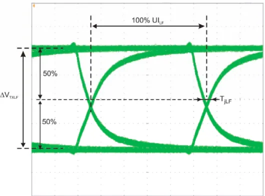
Figure 7 ― Definition of the jitter in the transmit EYE at Tp2 ... 26
Figure 8 ― Definition of the jitter in the low speed transmit EYE at Tp3... 28
Figure 9 ― PoCXP block diagram... 32
Figure 10 ― Simplified example state diagram ... 41
Figure 11 ― Link Overview ... 43
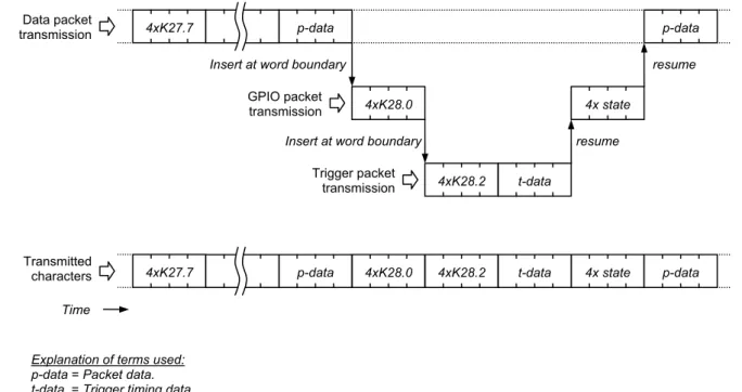
Figure 12 ― High speed link packet transmission example ... 51
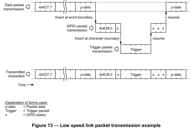
Figure 13 ― Low speed link packet transmission example ... 52
Figure 14 ― Low speed link trigger insertion example ... 53
Figure 15 ― Low speed trigger example... 58
Figure 16 ― Packet formation in Device – image data example ... 65
Figure 17 ― Packet processing in Device... 66
Figure 18 ― Control transaction – standard... 72
Figure 19 ― Control transaction – tentative acknowledgment... 73
Figure 20 ― Link test methodology... 80
Figure 21 ― Image stream structure... 86
Figure 22 ― Packing of 8 bit pixels... 97
Figure 23 ― Packing of 10 bit pixels... 97
Figure 24 ― Packing of 12 bit pixels... 98
Figure 25 ― Packing of 14 bit pixels... 98
Figure 26 ― Packing of 16 bit pixels... 98
Figure 27 ― Packing of 15 into 16 bits... 99
Figure 28 ― Scanning example ...102
Figure 29 ― Example 8x8 ROI in a VGA sized sensor...107
Figure 30 ― Matching Device and Host bit rates ...118
Figure 31 ― Examples of Device – Host connection schemes...120
Figure 32 ― Connection topology example part 1...121
Figure 33 ― Connection topology example part 2...122
Figure 34 ― Setting the bit tate ...127
Figure 35 ― Relationship with industry standards ...149
Figure 36 ― Example of GenTL Producer and GenTL Consumer hierarchy ...150
Figure 37 ― GenTL Module hierarchy ...152
Annex A: Figure 1 ― Deviation from normal attenuation behavior versus frequency ...165
Annex B: Figure 1 ― Electrical block diagram ...167
Annex B: Figure 2 ― Definition of the parameters in the transmit EYE at Tp2 ...169
Annex B: Figure 3 ― Signal transmitted at Tp3 by the Host showing baseline wander ...173
TABLE OF TABLES 表目次
Table 1 ― Supported high speed link bit rates... 7
Table 2 ― Labeling of CoaXPress products depending on their allowed bit rate... 14
Table 3 ― Connector indicator lamp states... 18
Table 4 ― Connector indicator lamp timings... 19
Table 5 ― Supported high speed link bit rates... 25
Table 6 ― Supported low speed link bit rate ... 27
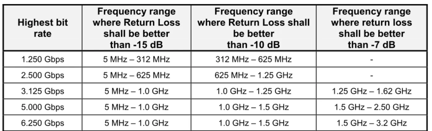
Table 7 ― Normative return loss frequency ranges for Host and Device ... 29
Table 8 ― Key to Host block diagram ... 32
Table 9 ― Key to Device block diagram ... 32
Table 10 ― K-code usage ... 45
Table 11 ― Packet types ... 49
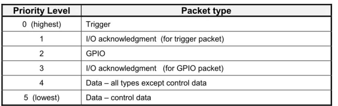
Table 12 ― Packet transmission priority ... 50
Table 13 ― Idle word format ... 54
Table 14 ― GPIO packet format ... 56
Table 15 ― Low speed link trigger packet format ... 60
Table 16 ― High speed link trigger packet format... 61
Table 17 ― I/O acknowledgment packet format... 61
Table 18 ― Data packet transmission format... 64
Table 19 ― Stream data packet format... 67
Table 20 ― Packet order on links – example ... 70
Table 21 ― Control command payload format ... 76
Table 22 ― Acknowledgment message format ... 78
Table 23 ― Link test packet format... 81
Table 24 ― PixelF coding ... 88
Table 25 ― Example PixelF values... 88
Table 26 ― Data width definition ... 89
Table 27 ― Mono definition ... 90
Table 28 ― Planar definition... 90
Table 29 ― Bayer definition... 92
Table 30 ― RGB definition ... 93
Table 31 ― RGBA definition ... 93
Table 32 ― YUV definition... 94
Table 33 ― YCbCr601 definition... 95
Table 34 ― YCbCr709 definition... 96
Table 35 ― Vertical tap formats...100
Table 36 ― TapG coding ...102
Table 37 ― TapG values ...103
Table 39 ― Rectangular image line marker ...110
Table 40 ― Arbitrary image header ...113
Table 41 ― Arbitrary line marker ...115
Table 42 ― Link state conditions ...117
Table 43 ― Control packet data size negotiation ...123
Table 44 ― Stream packet data size negotiation ...124
Table 45 ― Mandatory use case features...129
Table 46 ― URL Format – non-volatile memory ...133
Table 47 ― URL Format – vendor website ...134
Table 48 ― Bootstrap registers...137
Table 49 ― Bit rate codes...145
Annex A: Table 1 ― Return loss specification depending on frequency range ...159
Annex A: Table 2 ― Specification of the maximum attenuation for a cable ...161
Annex A: Table 3 ― Frequency range in which cable-like behavior is to be guaranteed ...163
Annex B: Table 1 ― High speed link parameters at the transmit (Device) side ...170
Annex B: Table 2 ― High speed link parameters at the receiver (Host) side...171
Annex B: Table 3 ― Low speed link parameters at the transmit (Host) side ...174
Foreword (まえがき)
JIIA (Japan Industrial Imaging Association) is the Japanese machine vision standards body.
The initial development of CoaXPress was by the CoaXPress Consortium. The JIIA CoaXPress Technical Committee is responsible for the preparation and maintenance of this standard. Contributions to the standard are also made by the CoaXPress Consortium and the CoaXPress Liaison Group, which is for members of the AIA (Automated Imaging Association) and EMVA (European Machine Vision Association).
JIIA (日本インダストリアルイメージング協会)はマシンビジョン向け規格を策定する日本の団体である。
CoaXPress の初期開発は CoaXPress コンソーシアムによって行われた。JIIA の標準化委員会は CoaXPress の 正式な規格化とその保守を担当する。CoaXPress コンソーシアムおよび AIA (Automated Imaging Association) と EMVA (European Machine Vision Association)からの有志によって結成された CoaXPress リエゾン委員会も この規格化に協力を行った。
1 Scope (適用範囲)
The CoaXPress digital interface was developed for high speed image data transmission and intended mainly for Machine Vision applications. The interface is also suitable for other imaging applications and for high speed data transmission in other fields.
CoaXPress uses 75 Ω coaxial cable as a physical medium.
CoaXPress デジタルインターフェースは主にマシンビジョン用途の高速画像伝送として開発された。本インターフ ェースは単に画像伝送に限らず,他の用途の高速データ伝送にも使用できる。
CoaXPress は伝送用物理媒体として 75Ωの同軸ケーブルを使用する。
2 Normative Reference (引用規格)
The following referenced documents are indispensable for the application of this document. For dated references, only the edition cited applies. For undated references, the latest edition of the referenced document (including any amendments) applies.
IEC 61169-8 Ed. 1.0:2007, Radio-frequency connectors ― Part 8: Sectional specification ― RF coaxial connectors with inner diameter of outer conductor 6,5 mm (0,256 in) with bayonet lock ― Characteristic impedance 50 ohm (type BNC)
IEC 61169-8 Ed. 1.0 Annex A.:2007, Information for interafce dimensions of 75Ω characteristic impedance connector with unspecified reflection factor
次に掲げる参考文書は,この文書の適用において不可欠のものである。発行年度が記載されている参考文書に ついては,参照した版を適用する。発行年度が記載されていない参考文書については,参考文書の最新版を (すべての改訂も含めて)適用する。
IEC 61169-8 Ed. 1.0:2007,無線周波数コネクタ-第 8 部:品種別通則 ― 差込みロック付 6.5 mm (0.256 in) 外部導体の内径をもつ RF 同軸コネクタ ― 特性インピーダンス 50 オーム(タイプ BNC)
IEC 61169-8 Ed. 1.0 Annex A.:2007,未規定の反射要素を伴う 75Ω特性インピーダンスコネクタのインターフ ェース外径情報
3 References and Definitions of Terms (参照と用語の定義) 3.1 Definition of Terms (用語の定義)
Device Can be any type of system that generates and transmits images or high speed data, as long as it is further responding and acting according to the CoaXPress specification. In most cases the Device will be a digital camera. A Device connection can also be on a frame grabber to allow for daisy chaining or data forwarding.
デバイス 「CoaXPress 規格に則って反応・作動する,あらゆる画像発生及び画像,高速データ伝送機器」と
定義可能<CAN>であるもの。ほとんどの場合,デバイスはデジタルカメラと考えられる。デイジー
チェーン,またはデータフォワードのためにフレームグラバにデバイスコネクションを配置すること も可能である<CAN>。
Host Can be any type of system that receives, records, processes or displays high speed data, as long as it is further responding and acting in accordance with the CoaXPress specification. In most cases the Host will be a simple interface card, or more powerful frame grabber or image processor.
ホスト 「規格に則って反応・作動する,あらゆる高速データ受信・記録・プロセス・ディスプレイ機器」と定
義可能<CAN>であるもの。ほとんどの場合,ホストはシンプルなインターフェースカード,あるいは
3.2 Abbreviations (略称)
CXP CoaXPress (コアックスプレス)
DT Device Transceiver circuit (デバイストランシーバ回路) Gbps Giga bit per second, 109 bits per second(ギガビット毎秒) HT Host Transceiver circuit (ホストトランシーバ回路)
Mbps Mega bit per second, 106 bits per second (メガビット毎秒) OCP Over Current Protection (過電流保護)
PoCXP Power over CoaXPress (パワーオーヴァーコアックスプレス) ppm parts per million (百万分率)
PRU Power Receiving Unit (受電ユニット) PTU Power Transmitting Unit (送電ユニット) ROI Region Of Interest (関心領域または対象領域)
3.3 Conventions (慣例)
“Shall” means a mandatory requirement.
<SHALL>は必須要件を意味する。
“Can” means an optional feature.
<CAN>はオプション要件を意味する。
Comments written in italic text do not form part of the specification, but are intended to help understand the requirements of the specification.
イタリック字体で記述されている部分はこの規格を成すものではないが,この規格の要求事項を理解する助けとな ることを意図している。
4 Introduction to CoaXPress (CoaXPressの序説) 4.1 Overview (概要)
CoaXPress is an interface to connect Devices (typically cameras) to Hosts (typically frame grabbers). It combines the simplicity of coaxial cable with state of the art high speed serial data technology, allowing up to 6.25 Gbps data rate per cable, plus device control and power in the same cable.
CoaXPress is a point to point scalable interface. The physical medium between the Device and Host is 75Ω coaxial cable.
An interface consists of one master link and optional extension links. Each link is associated with a coax cable. At the Device links are numbered, 0 for Master, and 1 to (n-1) for (n-1) extension links.
CoaXPress はデバイス(通常はカメラを指す)とホスト(通常はフレームグラバを指す)を接続するためのインターフ ェースのひとつである。シンプルな同軸ケーブルと最新の高速シリアルデータ技術を組み合わせ,ケーブル当た り最高 6.25Gbps のデータ伝送に加え,その同一ケーブルにてデバイス制御と電源供給までも可能にする。 CoaXPress はポイントツーポイントで接続する拡張可能なインターフェースである。デバイスとホストは 75Ωの同軸 ケーブルで接続する。 インターフェースは 1 本のマスタリンクとオプションの拡張リンクで構成される。各リンクは 1 本の同軸ケーブルに 関連付けられる。デバイス側にてマスタには 0 の番号が,(n – 1)本の拡張リンクには1~(n - 1)の番号が割り当て られる。 0 1 n-1 Host Extension link Master link coax coax coax Device
Figure 1 ― CoaXPress physical topology
0 1 n-1 拡張リンク 拡張リンク マスタリンク 同軸 同軸 同軸 ホスト デバイス 図 1 ― CoaXPress 物理トポロジ
Each link provides the following signaling connections:
A high speed serial link (usually Device to Host downlink), at up to 6.25 Gbps. A low speed serial link (usually Host to Device uplink), at 20.83˙ Mbps 1.
A power connection (Host to Device), up to 13W.
Comment: Future enhancements to the standard may allow a high speed link from the Host to the Device, allowing faster triggering and communications.
各リンクは以下の各信号接続を提供する。 6.25Gbps までのハイスピード シリアルリンク(通常はデバイスからホストへのダウンリンク) 20.83˙Mbps のロースピード シリアルリンク(通常はホストからデバイスへのアップリンク) 13W まで対応した電源供給(ホストからデバイスへ) コメント: 将来的に,より高速なトリガ入力や通信に対応したホストからデバイスへのハイスピードリンクが追加になる可能性 がある。
The link protocol defines the transfer of triggers, general purpose I/O, control data and high speed streaming data over a link.
リンクプロトコルが定義するものは1つのリンクにおける各トリガ伝送,汎用 I/O,コントロールデータおよび高速スト リームデータである。
Host Downlink
Uplink - Trigger / GPIO - Control data
Power
- Streaming data (e.g. video) - Trigger / GPIO
- Control data
Device
Figure 2 ― Link signaling connections and data flow
1 Note – the dot after the number 3 means “3 recurring”, i.e. the bitrate is 20.833333… Mbps.
- ストリームデータ (映像など) - トリガ / GPIO - コントロールデータ ダウンリンク 電源 - トリガ / GPIO - コントロールデータ アップリンク ホスト デバイス 図 2 ― リンクの各信号接続とデータの流れ
Both the uplink and downlink use 8B/10B coding.
Comment: 8B/10B is an industry-standard code that maps 8 bit data to 10 bit data to achieve DC balance on the link, while also allowing clock recovery by ensuring regular transitions.
アップリンク,ダウンリンクのいずれも 8b/10b コーディングを用いている。
コメント: 8b/10b はリンク上で DC バランスをとるために 8bit データを 10bit データに変換する業界標準の符号化方式で, 規則的な遷移を保証することでクロックのリカバリも可能となっている。
4.2 Use of Coax Cable (同軸ケーブルの採用)
There are several reasons for specifying coax:
Coax is acknowledged to be the best electrical medium for high speed data cables.
Coax does not suffer from intra-pair skew. Intra-pair skew is an important performance limiter for differential cables at high speeds.
Optimal bandwidth: a single-ended medium has less than half the loss of a shielded differential pair of the same diameter.
Very good EMI/EMC performance.
A large variety of possible cables allowed: thick ones for large distance, thin or flexible for shorter distance.
It is a low cost solution.
It is easy to install and terminate connectors in the field.
Terminating several coaxial cables in a common connector is relatively easy to achieve; terminating several shielded twisted pairs in a common connector is an expensive manual time consuming task. There is a legacy cable infrastructure.
同軸ケーブル使用を規定する根拠を以下に挙げる:
高速データ伝送のためのケーブルとして最高の電気特性をもつものと認められている
ペア内スキューを気にしなくて良い。ペア内スキューは高速伝送における差動接続において性能を出せない要 因になっている
最適な帯域:シングルエンド送信は同じケーブル外径なら差動に比べて損失を半分に抑えられる EMI/EMC 性能が非常に良い ケーブルの選択肢が豊富:太く長いケーブルから,柔軟性の高い短いケーブルまで ローコスト 現場へのケーブル導入も簡単 1つの共通コネクタにいくつかの同軸ケーブルを比較的簡単に結線できる(シールドされたツイストペア線を1つ の共通コネクタに結線するものは製作そのものが複雑で時間がかかる) 既にインフラに使われている歴史の古いケーブルである
In this way using coax cabling, whether a single coax or a set of coax cables is used, optimal performance is always achieved.
同軸ケーブルを 1 本または複数で使用するいずれの場合においても用途に最適化された性能を発揮することが できる<CAN>。
4.3 CoaXPress Speeds (CoaXPressの各スピード)
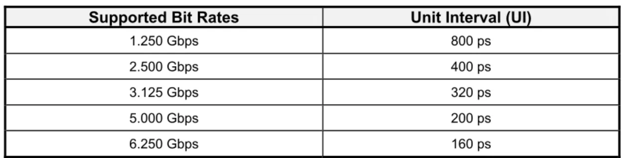
CoaXPress can operate at the speeds defined in Table 1.
Table 1 ― Supported high speed link bit rates
Bit Rate (Gbps) Discovery Rate
1.250
2.500
3.125
5.000 6.250
Comment: Additional speeds, both lower and higher, may be defined in future revisions of the specification.
CoaXPressは表 1で定義する各スピードにて動作可能である<CAN>。 表 1 ―ハイスピードリンクでサポートする各ビットレート ビットレート (Gbps) ディスカバリ レート 1.250 2.500 3.125 5.000 6.250 コメント: 将来的なバージョンアップにて新たにビットレートが(現在の下限未満および上限以上に)追加される可能性がある。
A Device (camera) shall support at least one of the defined bit rates in normal operation, plus a discovery rate (see section 10.1.2).
Comment: Usually the bit rate will be fixed, and will be the lowest speed that can be used to suite the Device’s performance. Unnecessary use of higher speeds will result in higher power consumption and will also reduce maximum cable length. The number of discovery bit rates is restricted to a small number of values to speed up the discovery process. More than one discovery bit rate is defined because a Device’s SERDES may not support 1.25 Gbps, especially as higher speeds are added in future.
デバイス(カメラ)側は通常動作におけるビットレートおよびディスカバリレートを最低一つずつサポートすること(セ クション10.1.2参照)<SHALL>。 コメント: 通常は各デバイスの性能に間に合う程度の低いビットレート固定で使うことが予想される。余計なスピードで使用す ると消費電力が大きくなり,ケーブル長も短くなる。ディスカバリ用ビットレートの種類はディスカバリ処理の高速化を 図るために最小限としている。複数のビットレートを用意したのは将来的にもっと高速なシステムが中心になった場 合にデバイス側の SerDes が 1.25Gbps をサポートしなくなる可能性があるためである。
A CoaXPress Host (frame grabber) shall support all the defined bit rates between 1.25 Gbps and the highest rate it supports.
CoaXPress products shall be labeled to indicate their maximum speed as described in section 4.11 . CoaXPress のホスト(フレームグラバ)は下限 1.25Gps からそのホスト(フレームグラバ)での上限のビットレートまで 全てをサポートすること<SHALL>。
CoaXPressの各製品にはセクション4.11 に示すようにサポートするビットレートの上限を表示するラベリングを行う こと<SHALL>。
4.4 Link Aggregation (リンクアグリゲーション)
CoaXPress Devices can use more than one cable in order to increase the maximum speed as described in section 4.1 above. The specification does not limit the number of cables which makes CoaXPress a future proof interface.
Comment: CoaXPress Devices slower than 6.25 Gbps can also be used with more than one cable. In some situations two cables running at 3.125 Gbps may be preferred to one cable at 6.25 Gbps as it will allow for longer cable length and may result in a lower system cost (because lower cost components can be used). CoaXPressではセクション4.1 で述べたように伝送速度を上げるため,複数本のケーブルを用いることができる <CAN>。ケーブルの本数には制限を設けないことで本インターフェースに将来的な拡張性をもたせている。 コメント: 6.25Gbps 未満の CoaXPress デバイスにケーブル1本でなく複数本を使用することもできる<CAN>。ケーブル 1 本 につき 3.125Gbps 伝送して 2 本構成で使った場合は,6.25Gbps をケーブル 1 本で伝送した場合より長いケーブ ルの使用が可能となる場合があり,(低コストな部品が使用できるため)システムコストを抑えられる場合がある。
4.5 Maximum Cable Length (最大ケーブル長)
The maximum cable length between Device and Host is dependent on the bit rate and the type of coax cable. For this reason CoaXPress certified cables are clearly marked with the maximum speed they support.
Example: At 6.25 Gbps the maximum cable length is around 25 meters for thin or highly flexible cables.
At the other extreme, lengths of over 200 meters are possible with thicker cables at 1.25 Gbps.
Comment: The link test mode allows for testing of the Bit Error Rate as a part of a diagnostics test, or for testing if an existing cable in an analog system can be reused for CoaXPress.
カメラ(デバイス) ― フレームグラバ(ホスト)間の最大ケーブル長はビットレートと同軸ケーブルの種類によって決 まる。このため,CoaXPress 準拠のケーブルには各ケーブルがサポートする最大のビットレートが明記される。 例: 高褶動型ケーブルもしくは細径ケーブルにおいて 6.25Gbps の伝送を行う場合は,ケーブル長は 25mほどに なる。極端な例では,1.25Gbps において太いケーブルを使うことで 200m 以上の長距離伝送も可能になる。 コメント: リンクテストモードでは診断テストのひとつとしてビットエラーレートのテスト,または従来のアナログシステムで使用し ていたケーブルを CoaXPress にて再利用可能か判断するテストを可能にしている。 4.6 Data Communication (データ通信)
Trigger, GPIO, control data and streaming data share bandwidth. Different types of data are transferred using a priority scheme. As a result of this priority scheme the bandwidth available for low priority data is automatically limited by the amount of used bandwidth for high priority data.
トリガ,GPIO,コントロールデータおよびストリームデータは帯域を共有する。異なる種類のデータはある優先順位 のルールに従って伝送される。その結果,優先順位の高いデータの使用量に応じて優先順位の低いデータが自 動的に制限されるというシステムになっている。
4.7 Trigger Accuracy (トリガ精度)
Trigger sequences have the highest priority. Triggers on a high speed link have an accuracy equal to ten transmitter bit periods, that is, better than ± 2 ns at 3.125 Gbps.
Triggers on a low speed link use an accurate timing correction value in the trigger words that allows for a low fixed trigger latency of 3.4 µs, with an accuracy of ± 4 ns.
Comment: In case a lower latency and/or higher accuracy are needed, the up-channel of an extension link can be used. This is not defined in the current revision of the specification.
トリガシーケンスは最も高い優先順位をもつ。ハイスピードリンクの各トリガは 1bit データ送信時間の 10 倍の精度 をもつ(これは「3.125Gbps 送信時で±2ns 超」の精度に相当する)。
ロースピードリンクのトリガはトリガワードの中に,正確なタイミング補正値をもつことによって,3.4μs という僅かな 固定レイテンシ±4ns のジッタを実現している。
コメント: より低レイテンシ/高精度なトリガを必要とする場合,拡張リンクのアップチャンネルを使用することもできる<CAN>。 ただし本リビジョンでは定義しない。
4.8 Power over Cable (ケーブルを通じての電源重畳)
The available power per cable is 13W at the Device, at a nominal 24V.
It is anticipated that 13W should be enough for most Devices with one CoaXPress connector; likewise 26W should be sufficient for Devices with two connectors (up to 12.5 Gbps); 39W for three connectors, etc.
Should more power be needed, or if the Device is not designed to be powered over the cable, a separate power input on the Device can be used.
CoaXPress Hosts are equipped with Device detection and short circuit protection to minimize the risk of damage should a Device other than a CoaXPress Device be connected.
ディバイスはケーブル 1 本あたり標準電圧 24V において 13W を消費できる。 13W あれば CoaXPress のコネクタ1つでほとんどのデバイスに対応が可能だと考えられる。コネクタを2つにすれ ば 26W まで(帯域は 12.5Gbps に)拡張でき,3つでは 39W になる。あとは省略する。 これ以上の電力が必要な場合,またはデバイスが接続するケーブルに電源を重畳する設計がなされていない場 合は電源を別にすることもできる<CAN>。 ホスト側はデバイス検出回路を装備し,CoaXPress 非対応のデバイスを接続してしまった場合などにショートが原 因となってデバイスが損傷することのないように対策する。 4.9 Data Integrity (データの整合性)
The control protocol (i.e. everything except for data) is designed to be tolerant of single bit errors. The data itself is protected by a CRC32 checksum which signals data errors. This revision of the protocol does not support data resend.
Comment: Data resend is not supported in the current revision because CoaXPress uses a physical medium that is designed to be nominally error free. Adding a resend capability will significantly increase the complexity of the protocol, add costs to the Devices that support it and decrease the real-time performance. CoaXPress can however inform the application whether there are bit errors and then an appropriate course of action taken.
コントロールプロトコル(= データを除く全て)は各シングルビットエラーが発生しても問題ないように設計されてい る。データ自身はデータエラーの有り無しを判断する CRC32 のチェックサムで保護される。データの再送につい ては本リビジョンではサポートされていない。 コメント: データ再送を本リビジョンでサポートしない理由は CoaXPress が通常ではエラーが発生しない物理媒体を使って いるからである。再送機能の追加はプロトコルを著しく複雑にしてしまうおそれがあり,デバイスがこれをサポートす るためのコストがかかり,さらにリアルタイム性が損なわれる。CoaXPress ではアプリケーションにビットエラーの発生 を通知するため,それを受けて適切な処置を行うことができる<CAN>。
For off-line testing of the complete imaging chain (Device – Cable(s) – Host), CoaXPress has a link test mode. In this mode the Device transmits a known data sequence at a programmable bit rate that allows measurement of the Bit Error Rate (BER) by the Host.
This mode can be used for a quick self test during power-up, but also as a diagnostics tool (to identify unreliable cables or connectors).
Also the link test mode can be used to verify link robustness in combination with legacy coax cables (for example when upgrading from analog to digital cameras using existing cables).
デバイス ― ケーブル ― ホストの画像システムが成立しているかどうかオフラインで検証するために,CoaXPress はリンクテストモードを備えている。このモードではデバイスは任意のビットレートで既知のデータシーケンスを送信 する。これによってホストはビットエラーレート(BER)を測定することができる。 このモードは電源投入時の簡易単体テストだけでなく,(信頼性の低いケーブルやコネクタを特定するための)診 断ツールとしても用いることができる<CAN>。 また,リンクテストモードは従来の同軸ケーブル(例:アナログカメラからデジタルカメラに移行したときの既存のケ ーブル)を用いた場合においてリンクのロバスト性検証にも用いることができる<CAN>。
4.10 Plug and Play (プラグアンドプレイ) 4.10.1 General (一般情報)
CoaXPress is designed to be plug-and-play.
CoaXPress contains mechanisms for automatic link setup (bit rate, link configuration scheme, Device detection) and Device and Host setup (image format, bit depth, data packing format, etc).
The link is designed to automatically recover after a loss of connection.
Comment: These mechanisms make CoaXPress hot-pluggable, and the protocol supports it. However this does not imply that an application will recover if a Device is unplugged and then reconnected. Also there is the potential for damage if a long cable with stored charge is connected.
CoaXPress はプラグアンドプレイに対応している。 CoaXPress は自動リンク設定(ビットレート,リンクコンフィグレーション,デバイス検出)とデバイス/ホスト設定(画 像フォーマット,ビット深度,データ格納フォーマットほか)のメカニズムを内包している。 リンクは接続断があった場合,自動的に修復されるよう設計されている。 コメント: このメカニズムによって CoaXPress はホットプラグを可能にしており,プロトコルもこれに対応したものになっている。 しかしながらこれはデバイスの接続断があってその後再接続されたときにアプリケーションソフトウェアが接続を修 復することを考慮したものではない。また,帯電している長いケーブルが接続された場合の損傷も懸念されることに なる。
4.10.2 GenICam (GenICam)
CoaXPress products shall support GenICam as described in section 10.3 .
CoaXPress製品はセクション10.3 に述べるようにGenICamをサポートすること<SHALL>。
4.11 Labeling and Use of the CoaXPress Logos (各CoaXPressロゴのラベリングと使用)
The use of CoaXPress logos on prodcuts or marketing material is only allowed for products that have been registered with JIIA. The registered products shall have been completed the compliance test procedure and have met the requirements.
Comment: JIIA will provide compliance tests procedure and the requirements for CoaXPress products
JIIA へ登録した製品のみが CoaxPress ロゴを製品またはカタログ等に使用することが許される。登録される製品 はコンプライアンステストプロシージャを完了し,その要件を満たしていること<SHALL>。
コメント: JIIA が CoaXPress 製品のコンプライアンステストプロシージャおよび要件を提供する。
4.11.1 Official CoaXPress Logo (CoaXPressの公式ロゴ)
The design of the official CoaXPress trademarked logo is shown in Figure 3. The trademark is pending under the Madrid Protocol.
CoaXPress公式商標ロゴの意匠を図 3に示す。この白黒のバージョンがマドリッドプロトコルにて国際商標申請中 である。
Figure 3 ― Official CoaXPress Logo
4.11.2 CoaXPress Logo Varieties (CoaXPressロゴの種類)
Varieties of CoaXPress logos are shown in Figure 4. The first row is the standard color logo, the second row a variant for use on black backgrounds, and the third row the monochrome version. The second column is the short-form logo to be used where space does not permit the full version.
CoaXPressの表示用ロゴ例を図 4に示す。最初の行は標準のカラーロゴ,2行目は黒背景用のもの,3行目は白 黒用である。2列目はロゴを十分に表示できるスペースがない場合に用いる省略型のロゴである。
Figure 4 ― CoaXPress logos
図 4 ― 各 CoaXPress ロゴ
Artwork is available from JIIA.
4.11.3 Product Labeling (製品へのラベリング)
CoaXPress compliant products shall be labeled official Logo and indication according to Table 2.
Table 2 ― Labeling of CoaXPress products depending on their allowed bit rate Maximum operational Bit Rate per Coax Compliance
(Gbps) Labeling 1.250 2.500 3.125 5.000 6.250 CoaXPressに準拠する製品には表 2に準じてラベリングを行うこと<SHALL>。 表 2 ―各ビットレートに対応した CoaXPress 製品のラベリング 同軸1 本あたりの最大動作ビットレート 準拠表示用 (Gbps) ラベリング 1.250 2.500 3.125 5.000 6.250
This label indicates that the product meets the CoaXPress specification, with a maximum supported bit rate per coax cable as indicated. It applies to all CoaXPress products, including Hosts, Devices and CXP-Cables.
Cable example: A given length of CXP-Cable marked as conforms to all the specification requirements for a maximum bit rate of 5 Gbps per coax. It will qualify for the lower bit rates as well. A longer length, but using the same cable type, might only qualify as .
Comment: This labeling is purely indicating CoaXPress compliance. The product vendor is free to label their products to indicate other features in addition to the compliance label.
このラベルが貼られている製品は CoaXPress の仕様を満たし,同軸ケーブル 1 本あたりの最大ビットレートを伝 送可能であることを示している。ラベルはホスト,デバイス,CXP ケーブルを含む全ての CoaXPress 製品に適用さ れる。 ケーブル表示例: がラベリングされたケーブルでは同軸1本につき最大 5Gbps までのビットレートに対応 する。それ以下のビットレートであれば同じケーブルで十分となる。ケーブル長が伸びると,同じタイプのケーブル を使っても 程度の性能しか出せない可能性がある。
コメント: このラベルは純粋に CoaXPress 準拠を表示すものである。製品メーカが自社製品の他の機能を表示するためにラ ベルを追加するのは任意となる。
4.11.4 Product Feature Bar (製品への機能表示)
It is recommended that CoaXPress product information (e.g. in brochures, adverts and websites) is labeled with a feature bar in the style shown in Figure 5.
CoaXPress製品の情報(チラシや広告,ウェブサイト等)には図 5に示すような機能バーをつけて表示を行うことを 推奨する。
Figure 5 ― Feature bar
図 5 ― 機能バー
The first box gives the maximum speed, in the format listed in section 4.11.3, and the second box gives the connector type and number of links.
Artwork is available from JIIA.
Comment: This gives a simple “at a glance” guide to help end users and system integrators choose compatible cameras, cables and frame grabbers.
最初のボックスはセクション4.11.3にあるフォーマットに従って最大スピードを,2つ目のボックスにはコネクタの種 類とリンク数を記載している。
ロゴの電子データは JIIA より供給される。
コメント: これはエンドユーザやシステムインテグレータに CoaXPress に準拠したカメラ/ケーブル/フレームグラバであるこ とが「一目で」わかるようにするためのシンプルな方法である。
5 Cable and Connector Specification (ケーブルとコネクタの仕様) 5.1 Introduction (序文)
This section defines CoaXPress cables and connectors from the point of view of a manufacturer of a Device or Host. See “Annex A: Detailed Cable Specification” for detailed cable requirements for cable manufacturers.
CoaXPress uses 75 Ω coaxial (“coax”) cables.
A cable compliant with this specification is called a CXP-cable; a bundle of coax cables including connectors is called a CXP-multi-cable. At cable ends one shall have CXP-connectors, or when grouped at ends of a CXP-multi-cable, can have CXP-multi-connectors. The connectors at the Device and the Host side are the receiving jack CXP-connectors and jack CXP-multi-connectors.
Comment: The use of an approved CoaXPress cable is the simplest way to ensure reliable operation, particularly at high speeds and/or long cable lengths. However at lower speeds, and/or with shorter cables, many legacy 75Ω coax cables should operate perfectly.
本セクションでは CoaXPress のケーブルおよびコネクタについてデバイス製造者およびホスト製造者の視点から 定義している。ケーブル製造者向けの詳細な必要条件については“附属書 A: ケーブル仕様の詳細”を参照。 CoaXPress では 75Ωの同軸(“coax”)ケーブルを使用する。 この規格書に準拠しているケーブルは「CXP ケーブル」の名前で総称することとする。これには「CXP マルチケー ブル」と称する複数の同軸を束にしたケーブルも含む。ケーブル端末はすべて「CXP コネクタ」を備えることとし <SHALL>,CXP マルチケーブル端末の場合は「CXP マルチコネクタ」を備えることができる<CAN>。デバイスと ホスト側のコネクタは受け側の「CXP コネクタジャック」または「CXP マルチコネクタジャック」とする。 コメント: 認定済の CoaXPress ケーブルを使用することは特に長いケーブルを高速で使用する場合に信頼性の高いシステ ムを構築するための近道となる。比較的短いケーブルで高速でない場合はそれまで使用されてきた多くの 75Ωの 同軸ケーブルでも十分な動作が可能となる。 5.2 Connectors (コネクタ) 5.2.1 Single Connectors (シングルコネクタ)
Connectors shall be of 75 Ω-BNC type, as defined in IEC 61169-8 annex A. The connectors shall also comply with all other requirements in IEC 61169-8 other than the requirement for 75 Ω instead of 50 Ω.
Comment: IEC 61169-8 does not define insertion loss requirements; however this requirement is included in the overall cable and electrical characteristics defined in this specification.
コネクタは IEC 61169-8 annex A にて定義されている 75Ωの BNC 型とすること<SHALL>。コネクタは IEC
コメント: IEC 61169-8 ではインサーションロスに関する要求仕様については定義していない。しかしながらこの要求仕様は 本規格書における全てのケーブルおよび電気特性に含まれることになる。
5.2.2 Multi-Connectors (マルチコネクタ)
CXP-multi-connectors shall not be used in systems compliant with this revision of the standard.
Comment: An approved connector type will be defined in a future revision of CoaXPress.
本規格書のこのリビジョンでは CXP マルチコネクタを使用してはならない<SHALL NOT>。
コメント: CoaXPress の将来的なリビジョンで正式なコネクタの種類が定義される予定である。
5.2.3 Couplers (カプラ)
CoaXPress cables can be joined with inline 75 Ω BNC couplers, however these will reduce the usable cable length.
Comment: Couplers rated to at least the operational frequency should be used (e.g. 3.125 GHz for 6.25 Gbps), however even the best may reduce cable length by around 5m at 6.25 Gbps.
CoaXPress のケーブルはインライン型の 75ΩBNC カプラに連結することができる<CAN>が,これらはケーブル長
の上限を制限すると考えられる。
コメント: 少なくとも動作周波数が見積もられたカプラを使用するべきであるが,6.25Gbps では最適なものでもケーブル長が 5m 程度短くなる可能性がある。
5.2.4 Contact Material (接点部材質)
It is recommended that the center contact is gold plated, and the outer contact either nickel or white bronze plated.
Comment: These are proven contact materials. Nickel and white bronze (an alloy of copper, tin and zinc) are compatible materials, i.e. they can be used together. Additional approved materials may be added in future revisions of the standard.
中心コンタクトは金めっき,ほかの部分はニッケルめっきまたはホワイトブロンズめっきを推奨する。
コメント: これらは実績のあるコンタクト材質(めっき処理)である。ニッケルめっきとホワイトブロンズめっき(銅,錫および亜鉛 の合金)には互換性がある(混在して使用することも可能<CAN>)。本規格の将来的なリビジョンでほかの承認され た材質(めっき処理)が追加される可能性あり。
5.3 Multiple Cables for Link Aggregation (リンクアグリケーション用マルチケーブル)
When more than one physical cable is used to form a link, all the cables shall be nominally the same type and length. The difference in length of the cables shall be less than 1m.
Comment: This is to limit the skew in data packets between the multiple cables, and hence to minimize the FIFO requirements at the Host to realign the data. A 1m difference corresponds to approximately a 5ns skew, which is 4 words at 25 Gbps, so easily handled by a FIFO.
リンクを形成するために複数のケーブルを使う場合は,全てのケーブルを同じ構成,同じ長さにすること
<SHALL>。各ケーブル長の差異は 1m 未満とすること<SHALL>。
コメント: これはケーブル間のデータパケットについてスキューのばらつきを抑え,ホスト側の FIFO にてデータの再アライメ ントを行う必要性を最小限に抑えることにもなる。1m の差異は 5ns のスキューに相当し,これは 25Gbps において 4 ワード分に相当するため,FIFO を使用することで簡単に扱える。
5.4 Connector Indicator Lamps (コネクタの表示ランプ)
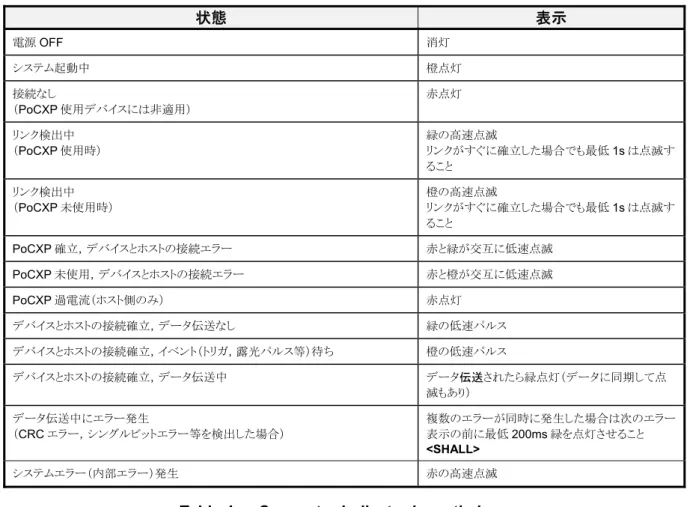
It is recommended that Devices and Hosts have an indicator lamp by each connector. If fitted, these lamps shall include the following indications:
Table 3 ― Connector indicator lamp states
State Indication
No power Off
System booting Solid orange
Powered, but nothing connected
(not applicable to a Device reliant on PoCXP power)
Slow pulse red Link detection in progress, PoCXP active Fast flash green
Shown for a minimum of 1s even if the link detection is faster
Link detection in progress, PoCXP not in use Fast flash orange
Shown for a minimum of 1s even if the link detection is faster
Device / Host incompatible, PoCXP active Slow flash alternate red / green Device / Host incompatible, PoCXP not in use Slow flash alternate red / orange PoCXP over-current (Host only) Solid red
Device / Host connected, but no data being transferred Slow pulse green Device / Host connected, waiting for event (e.g. trigger, exposure pulse) Slow pulse orange
Device / Host connected, data being transferred Solid green whenever data transferred (i.e. blinks synchronously with data)
Error during data transfer
(e.g. CRC error, single bit error detected)
500ms red pulse
In case of multiple errors, there shall be at least 200ms green before the next error is indicated
デバイスおよびホストには各コネクタ部に表示ランプの付加を推奨する。付加可能な場合,各ランプは以下に示 す状態:表示を含むこと<SHALL>。 表 3 ― コネクタ部表示ランプの各状態 状態 表示 電源OFF 消灯 システム起動中 橙点灯 接続なし (PoCXP 使用デバイスには非適用) 赤点灯 リンク検出中 (PoCXP 使用時) 緑の高速点滅 リンクがすぐに確立した場合でも最低1s は点滅す ること リンク検出中 (PoCXP 未使用時) 橙の高速点滅 リンクがすぐに確立した場合でも最低1s は点滅す ること PoCXP 確立,デバイスとホストの接続エラー 赤と緑が交互に低速点滅 PoCXP 未使用,デバイスとホストの接続エラー 赤と橙が交互に低速点滅 PoCXP 過電流(ホスト側のみ) 赤点灯 デバイスとホストの接続確立,データ伝送なし 緑の低速パルス デバイスとホストの接続確立,イベント(トリガ,露光パルス等)待ち 橙の低速パルス デバイスとホストの接続確立,データ伝送中 データ伝送されたら緑点灯(データに同期して点 滅もあり) データ伝送中にエラー発生 (CRC エラー,シングルビットエラー等を検出した場合) 複数のエラーが同時に発生した場合は次のエラー 表示の前に最低200ms 緑を点灯させること <SHALL> システムエラー(内部エラー)発生 赤の高速点滅
Table 4 ― Connector indicator lamp timings
Indication Timing (±20%)
Fast flash 12.5Hz (20ms on, 60ms off) Slow flash 0.5Hz (1s on, 1s off) Slow pulse 1Hz (200ms on, 800ms off)
表 4 ― コネクタ部表示ランプ:タイミング
表示 タイミング (±20%)
高速点滅 12.5Hz (20ms オン,60ms オフ)
低速点滅 0.5Hz (1s オン, 1s オフ)
低速パルス 1Hz (200ms オン,800ms オフ)
It is recommended that both Device and Host have an option to turn off the indicator lamps, for example to allow use in darkened environments. An additional recommended option is to only show error conditions on the lamps.
Examples: If the Device is waiting for trigger, and the Host is ready to accept data, the Device will
Host, with the Device continuously streaming data, the Device would show solid green and the Host a slow orange pulse.
Comment: These indications are designed to help a user understand what the system is (or more importantly, isn’t) doing. They will also help Technical Support staff to diagnose customer issues.
デバイス側/ホスト側ともに,表示ランプを OFF にできる機能を付加することを推奨する。例えば,遮光された環 境で(その状態を保ちながら)の使用を可能にするためである。さらにエラー発生時のみランプを表示させるオプ ションの付加を推奨する。 例:デバイスがトリガ待機中の場合,ホスト側はデータを受け取る準備をし,デバイスは低速で橙をパルス表示し, ホスト側は低速で緑をパルス表示する。トリガを入力完了するとデバイスがデータを出力するのでデバイス側表示 ランプは緑を点灯し,ホスト側は低速な橙パルス表示となる。 コメント: これらの表示はシステムが正しく動作中であるか(あるいは「動作していない」ということを示すのがより重要な場合も ある)ユーザが理解するための補助情報となるよう設計されている。個別のユーザにおけるトラブルをテクニカルサ ポート担当者が診断するための補助情報となる場合もある。
6 Electrical Specification (電気的仕様) 6.1 Introduction (序文)
This section defines the electrical parameters from the point of view of a manufacturer of a Device or Host. Reference to datasheets of an approved CoaXPress transceiver (e.g. section C.3 ― Ref 1) may be useful.
See “Annex B: Chipset Requirements” for detailed requirements for chipset designers (parts of which may also be useful to Device and Host manufacturers as part of product compliance testing).
本セクションではデバイス製造者およびホスト製造者の視点から電気特性について記載している。CoaXPress適 合トランシーバのデータシート(例: セクションC.3 ― Ref 1)も有用な資料となり得る。
チップセット設計者向けの詳細な必要条件については“附属書 B: チップセットの必要条件”を参照(デバイス製 造者およびホスト製造者にとっても主に製品動作検証の観点で有用な資料となっている)。
6.2 Top Level Overview (全体構成)
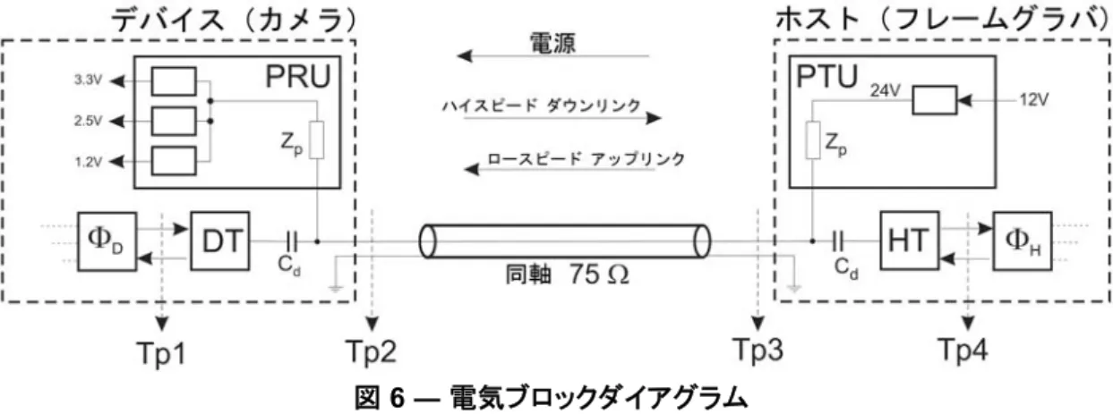
Figure 6 shows the electrical block diagram of one link in a CoaXPress system, with the Device on the left linked to the Host on the right by a coax cable with a characteristic impedance of 75 Ω. The figure also defines the test points Tp1 to Tp4 used in this section.
The high speed link is usually the downlink from the Device to the Host, and the low speed link is in the opposite direction, so usually the uplink from the Host to the Device.
Figure 6 ― Electrical block diagram
Comment: Voltages shown at the output of the PRU and the input to the PTU are typical examples.
図 6にCoaXPressの仕様に準じた単一リンクでのシステム概要を示す。左側にデバイス,右側にホストがあり,互い に特性インピーダンス 75Ωの同軸ケーブル1本で接続されている。この図では本セクションで用いる検証ポイント としてTp1~Tp4 を定義している。
ハイスピードリンクは通常デバイスからホストへ,別名ダウンリンクと呼ばれるもののことをいう。ロースピードリンクは 逆にホストからデバイスへのアップリンクと呼ばれるもののことをいう。