マルチカスプ磁場を装備するプラズマ発生装置 AIT-PID の特性
Characetristics of Compact Plasma Device AIT-PID with Multicusp Magnetic Confinement
高村秀一†,内藤信寛†,西川賢†,恵比根拓也†,宮本隆徳† †
Shuichi TAKAMURA†, Nobuhiro NAITO†, Masaru NISHIKAWA†, Takanori MIYAMOTO† †
Abstract A unique plasma generation device AIT-PID is developed for PWI (Plasma-Wall
Interaction) studies toward fusion reactor. It has a power-saving characteristics as well as some compactness by employing multicusp magnetic field configuration instead of strong axial magnetic field. The helium as well as argon plasmas are generated, showing an outstanding property of production of hot electron component which can be controlled by changing the working gas pressure. An azimuthally asymmetric confinement depending on the direction of magnetic field lines, particularly for energetic electrons has been found. Some discussions on the physical mechanisms are represented.
1. Introduction
Towards ITER (International Thermonuclear Experimental Reactor) and DEMO (DEMOnstration Reactor) material selection for the plasma-facing components inside the reactor is essential to ensure a stable sustainment of tokamak plasma confinement and nuclear burning since the steady as well as transient heat and particle loads are enormous and critical in terms of thermal resistance of the components and hydrogen inventory on the wall1, 2).
Tungsten seems to be one of the most promising candidates owing to a high melting temperature, a low sputtering yield and a relatively small tritium inventory. However, we have neither much experience in the environment of high power condition3), nor the
sufficient characterization as the plasma-facing material. For example, the bubbles and holes formation at high surface temperature4) and the arborescent nanostructure
at relatively low surface temperature are the typical morphology of damaged surface which may have a weak thermal resistance in terms of impurity release by surface melting due to lost thermal conduction to the deep bulk, an easy triggering of unipolar arc5~11) and a
† Faculty of Engineering, AIT, Toyota 470-0392
††Graduate School of Engineering, AIT, Toyota 470-0392
dust formation.
We need some test facilities to investigate material properties of tungsten wall for various points of view in the reactor relevant condition. Several linear plasma simulators12-16) have been working for the above
purposes, including NAGDIS-I, II. Compact plasma device for such PWI (Plasma-Wall Interaction) studies is very helpful to investigate, for example, how to avoid the helium damage of tungsten surface, what is the surface characteristics for nanostructured tungsten surface, and possible utilization of such nanostructured tungsten with a suppression of induced arcing.
In the present paper the qualifications of new plasma device for PWI studies is introduced, focusing on the plasma confinement properties and demonstrating a power-saving compactness. Some preliminary characteristics has been published12),
showing the presence of hot electron component and effectiveness of PWI studies, especially helium damage.
2. Device specification
In order to investigate PWI, especially under high heat and particle flux condition, we need to have a high plasma density more than 11018m-3 with a high
electron energy. The device which we concern is called AIT-PID (Aichi Institute of Technology – Plasma Irradiation Device), and has a machine structure shown in Fig. 1. It is equipped with three pairs of neodymium permanent magnet bars composing multicusp magnetic configuration and a solenoidal winding underneath the permanent magnets, producing a weak axial magnetic field. Figure 2 shows the cross section of the discharge chamber at the mid position. We have magnetic-free zone on the axis, where the LaB6 ceramic cylindrical
cathode with the diameter of 20 mm is located at the end of this zone. The Lorentz force exerted by a very small magnetic field and the heating current through the ceramic solenoid is so weak that a long life time of fragile LaB6 cathode is ensured. The grounded anode
made of copper is put at downstream side between mid and end, and its center has a hole with a diameter of 35mm. It produces the gas compression at the discharge region by a factor of 2 due to a narrow gas channel. The gas compression is also enhanced by the plasma plugging although it is modest, a few %, at the discharge current of 20A. A higher plugging would be foreseen at higher discharge current. The cathode-facing surface of the anode has a tapered structure as shown in Fig. 1.
Multicusp magnetic configuration has been employed by many plasma devices17-23), but not for the
plasma simulator aiming PWI studies. Figure 3 shows horizontal distributions of vertical magnetic field intensity obtained by a numerical analysis for three kinds of multi-cusp magnetic configurations, 4, 6 and 8 poles. A permanent magnet is approximated by a single line magnetic dipole. The eight pole cusp gives a higher magnetic field barrier with a wide weak field space for plasma containment. However, more pole bars inhibit the installation of accessing ports. On the other hand, less pole ones give a weaker magnetic barrier with a narrower space for the contained plasma so that an optimization is needed. We have employed 6 pole configuration. The magnetic field distribution was measured using gauss meter and compared with the numerical analysis. The measurement gives a good agreement with the analysis12). We can determine the
magnetic dipole moment strength per unit length of
Fig. 1 Shematic view of the device AIT-PID.
Fig. 2 Cross-section at mid position of discharge chamber.
Fig. 3 Horizontal distribution of vertical magnetic field intensity for three kinds of multi-pole magnetic configuration.
Fig. 4 Contours of equi-magnetic field intensity on the cross-section of discharge chamber for 6-pole magnetic configuration.
0.524H A.
Figure 4 shows contour map of equi-magnetic field intensity on the cross-section of discharge chamber for 6-pole magnetic configuration. The behavior of magnetic line of force is shown in Fig. 5. In both figures, the inner surface of vacuum chamber with the diameter of 133.8 mm is drawn with a thick line of circle.
The axial magnetic field is also analyzed numerically with Biot-Savart formula for two locations indicated in Fig. 6, and shown in Fig. 7 by broken lines, and measured with a gauss-meter, indicated by solid triangles and circles in Fig. 7. The temperature increase of winding gives an upper limit for the solenoidal current up to about 15A which corresponds to about 6mT at mid point.
Usually a strong magnetic field more than roughly 0.1T has been employed in linear plasma devices4~8, 13 ~16) for the radial confinement of produced plasma. The
consumed electric power for energizing the magnetic coils is sometimes very large. Not only a contribution
to power saving compactness, but also a favorable effect on the maintenance of directly heated LaB6
ceramic cathode have been obtained by a very weak Lorentz stress on LaB6 solenoid, as indicated above.
The heat removal from the inner wall is very important in such a high-power and compact plasma device. The main discharge chamber has a double wall structure through which a cooling water circulation ensures the efficient heat removal. The water supply of 4.5L/min with a temperature rise of 5 degree C carries out 70% of the power injected into the device which is composed of discharge and cathode heating powers at the level of discharge current of 20A.
3. Plasma parameters
As shown in Figs. 1 and 8, a motor-driven scanning probe system is employed for the Langmuir probe diagnostics. It moves radially beyond the chamber center and is connected to A-D converter controlled with PC to have digital data. The scanning speed is 0.62cm/s and a series of triangular voltage (+40 to -100V) is fed to the tungsten probe tip (0.8mm in diameter and 2.3mm in length) so that I-V characteristics are obtained every 0.031mm with a sampling time of 500 s .
Fig. 5 Pattern of magnetic field lines for 6-pole magnetic configuration.
Fig. 6 Solenoidal winding underneath a series of permanent magnets.
Fig. 7 Axial magnetic field intensities as a function of coil current at two locations marked on Fig. 6.
Fig. 8 Schematic view of Langmuir probe driving system.
Spectroscopic measurements have been done through the quartz vacuum window from ultraviolet through infrared range (300-800mm) using fiber optics and spectrometer (Ocean Optics Inc., HR-4000). An emission spectrum from helium plasma has been obtained, showing a series of helium atomic and ionic lines. Any impurity lines are not detected under the current discharge condition12).
3.1. Discharge control
We are focusing on the helium discharge although the argon gas is much easier for obtaining the discharge with a less discharge voltage. The helium gas flow rate is larger than around 60sccm to have substantial discharge current with a modest discharge voltage less then around 100V. The discharge voltage of 100V is not a critical figure but we must be careful to minimize the sputtering of cathode-supporting material, mainly molybdenum and also LaB6 itself due to helium ion
bombardment. The axial magnetic field Bz has some
influence on the discharge voltage as shorn in Fig. 9 from which 1.7mT for Bz is employed for the normal
operation as giving a minimum discharge voltage. It seems that the optimum Bz giving a minimum discharge voltage may depend on the small angle of LaB6 cylinder with respect to the axis.
As described below, the discharge voltage has some influence on the electron energy content, especially high energy electron component. The gas pressure has also affect the discharge voltage as shown in Fig. 10. The lower the gas flow rate is, the higher the discharge voltage is. We should note that the discharge voltage is also determined by an emission condition of LaB6
cathode so that the voltage is sensitive to its surface
condition and the heating current.
3.2. High energy electron component
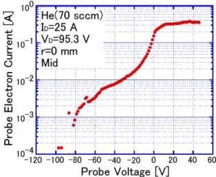
The one of outstanding characteristics of AIT-PID is the presence of hot electron component in addition to bulk near-Maxwellian electrons. Figure 11 shows a typical logarithmic plot of probe electron current as a function of probe biasing voltage. The tail of electron energy distribution is clearly seen with a truncation of tail at almost the discharge voltage. The slope of hot component gives an apparent electron temperature of hot components. The probe electron current is subtracted by the current coming from hot electrons so that it may give the curve corresponding to bulk electrons.
Figure 12 gives the plasma parameters thus obtained as a function of discharge current for a working gas of
Fig. 9 Dependence of discharge voltage on the axial magnetic field for helium as a working gas.
Fig. 10 Dependence of discharge voltage on the gas pressure.
Fig. 11 Semi-logarithmic plot of probe electron current vs. probe voltage.
He. The electron density of more than 1 .0 1018m-3has been obtained in the discharge current range above 20 A. Hot electron temperature is in the range between 30 ~45 eV and the bulk temperature is 3~5 eV. The fraction of hot component is about 8% independent of discharge current.
The working gas condition for Ar is 0.1~0.3 Pa in the discharge region in which a low gas pressure gives also the presence of hot electrons similar to the He case.
4. Radial confinement with multicusp magnetic configuration
4.1. Radial distribution of plasma density
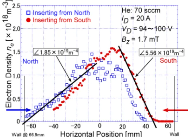
A kind of asymmetry of electron density distribution has been observed in the radial direction. Typical profiles obtained with Langmuir probe are shown in Fig. 13 for two directions of probe insertion from the north and the south through the horizontal ports, which are shown by open squares and solid circles, respectively. The tendency of asymmetry is similar for both insertion cases, that is, the density gradient of the north side, 1.851019m-4is smaller than that of the south side, 5.561019m-4. In other words, a sharp density gradient is seen on the south side.
The distribution of the hot electron fraction is plotted in Fig. 14 with solid triangles, indicating a better confinement in the south side than in the north side. Concerning the magnetic configuration property, there is no difference in magnitude of cusp field. Only the azimuthal direction of magnetic line of force is opposite, clockwise or anti-clockwise with respect to the axis as shown in Fig. 5.
We examined similar measurements for oblique port as shown in Figs. 15 and 16, which make clear that the oblique south side at upper port gives a weak confinement, while the oblique north side at upper port does a good radial confinement. Then, we understand that the good and weak confinement regions appear azimuthally every 60 degrees in turn.
4.2. Azimuthal view of plasma confinement
In order to obtain, an overall view of plasma confinement, a total visible light emission is taken as a photo from the pumping side, axially opposite to the cathode. The light emission profile through the anode hole is shown in Fig. 17, indicating a strong emission boundary with a white line. A thick area with strong emission corresponds to a location where the confinement of hot electron component is better than at the other area. So we consider that the emission may be
Fig. 12 Discharge current dependence of plasma parameters: the electron density, the fraction of hot electron component and the temperature of bulk and hot electrons.
Fig. 13 Horizontal profiles of electron densities for two insertion directions of driven probe.
Fig. 14 Horizontal profiles of electron density, fraction of hot electron component, and plasma potential. The probe was inserted from the horizontal port at the south.
a measure of hot electrons population. Such a profile is the same for the reversed axial magnetic field, and the Ar plasma with a relatively low gas pressure gives a similar emission profile as shown in Fig. 18.
We would like to discuss possible physical mechanisms bringing, such an azimuthal asymmetry, focusing on the loss of energetic electrons due to E×B drift.
(1) If the electric field E is considered as an axial one coming from the discharge, then it gives a completely opposite results. It means that the direction of E×B is outward in the good confinement region.
(2) If the electric field E is considered just in front of the anode since the plasma potential is positively around 4 V with respect to the grounded anode, then E ×B gives a right direction to make the flow of energetic electrons inward for good confinement region. However the electron Larmour radius is fairly large ~ 1 cm for 30 eV with 15 Gauss and is much larger than the sheath thickness in front of the anode.
A fluctuation induced transport may be another candidate to explain. However, it is beyond the present scope.
5. Summary and conclusion
We developed a unique plasma device aiming PWI studies for fusion reactor, AIT-PID which has a power saving characteristics with a compactness. In addition, the outstanding property is the generation of hot electron component which can be controlled by, for example, gas pressure.
An azimuthally asymmetric confinement of plasma, especially for hot electron component has been found. Some discussions on the physical mechanism for such an azimuthal asymmetry are presented, but it is still open to be solved.
Acknowledgement
This work was performed with the support of
Fig. 15 Radial profiles of electron density, fraction of hot
electron component, and plasma potential. The probe insertion was grazing from the south side.
Fig. 16 Radial profiles of electron density, fraction of hot electron component, and plasma potential. The probe insertion was grazing from the north side.
Fig. 17 Total light emission profile for helium discharge.
Fig. 18 Total light emission from (a) helium with a reversed B compared to Fig. 17 and (b) argon discharges.
Grant-in-Aid for Scientific Research (B) (20360414) and Grant-in-Aid for challenging Exploratory Research (40023254). The author would like to thank Prof. N. Ohno for his valuable discussions and T. Minagawa and Y. Tomida for their technical assistance.
References
1) A. Loarte, B. Lipschultz, A.S. Kukushkin et al., “Chapter 4: Power and particle control”, Nucl. Fusion Vol. 47, S203-S263, 2007.
2) ITER Physics Expert Group on Divertor, ITER Physics Expert Group on Divertor Modelling and Database, and ITER Physics Basis Editors, “Chapter 4: Power and particle control”, Nucl. Fusion Vol. 39, pp.2391-2469, 1999.
3) H. Hoehle, J. Stber, A. Hermann, W. Ksparek, F. Leuterer et al., “Extension of the ECRH operational space with O2 and X3 heating schemes to control tungsten accumulation in ASDEX Upgrade”, Nucl. Fusion Vol.51, pp.083013(10 pages) , 2011.
4) M.Y. Ye, S. Takamura and N. Ohno, “Study of hot tungsten emissive plate in high heat flux plasma on NAGDIS-I”, J. Nucl. Mater. Vol. 241-243, pp.1243-1247, 1997.
5) S. Takamura, N. Ohno, D. Nishijima and S. Kajita, “Formation of Nanostructured Tungsten with Arborescent Shape due to Helium Plasma Irradiation”, Plasma Fusion Res. Vol. 1, pp.051(2 pags), 2006.
6) M.J. Baldwin and R.P. Doerner “Helium induced nanoscopic morphology on tungsten under fusion relevant plasma conditions”, Nucl. Fusion Vol. 48, pp.035001(5 pages), 2008.
7) S. Kajita, S. Takamura and N. Ohno, “Prompt ignition of a unipolar arc on helium irradiated tungsten” Nucl. Fusion Vol. 49, pp.032002(4 pages), 2009.
8) M.J. Baldwin, R.P. Doerner, D. Nishijima, K. Tokunaga and Y. Ueda, “The effects of high fluence mixed-species (deuterium, helium, beryllium) plasma interactions with tungsten”, J. Nucl. Mater. Vol. 390-391 pp.886-890, 2009. 9) S. Takamura, T. Miyamoto and N. Ohno, “Deepening of
Floating Potential for Tungsten Target Plate on the way to Nanostructure Formation”, Plasma Fusion Res. Vol. 5 pp.039(2 pages), 2010.
10) S. Takamura and T. Miyamoto, “Recovery of Tungsten Surface with Fiber-Form Nanostructure by the Argon Plasma Irradiation at a High Surface Temperature”, Plasma Fusion Res. Vol. 6, pp.005(2 pages), 2010.
11) M. Tokitani, S. Kajita, S. Masuzaki, Y. Hirahata, N. Ohno et al., “Exfoliation of the tungsten fibreform nanostructure by unipolar arcing in the LHD divertor plasma”, Nucl.
Fusion Vol. 51 pp.10201(5 pages), 2011.
12) S. Takamura, T. Tsujikawa, Y. Tomida, K. Suzuki, T. Minagawa, T. Miyamoto and N. Ohno, “Compact Plasma Device for PWI Studies“, J. Plasma Fusion Res. SERIES, Vol. 9, pp.441-445, 2010.
13) W. Bohmeyer, A. Markin, D. Naujoks, B. Koch, G. Krenz M. Baudach and G. Fussmann, “Decomposition and sticking of hydrocarbons in the plasma generator PSI-2”, J. Nucl.
Mater. Vol. 363-365 pp.127-130, 2007.
14) F. Scotti and S. Kado, “Comparative study of recombining He plasmas below 0.1 eV using laser Thomson scattering and spectroscopy in the divertor simulator MAP-II”, J. Nucl. Mater. Vol. 390-391, pp.127-130, 2009. 15) B. De Groot, R.S. Al, R. Engeln, W.J. Goedheer, O.G.
Kruijt et al., “Extreme hydrogen plasma fluxes at Pilot-PSI enter the ITER divertor regime” Fusion Eng. Design, Vol. 82, pp.1861-1865, 2007.
16) H.J. Van Eck, W.R. Koppers, G.J. van Rooij, W.J. Goedheer and B. De Groat, “Pre-design of Magnum-PSI: A new plasma–wall interaction experiment”, Fusion Eng. Design Vol. 82, pp.1878-1883, 2007.
17) I. Dey and S. Bhattachartjee, “Anisotropy induced wave birefringence in bounded supercritical plasma confined in a multicusp magnetic field”, Appl. Phys. Letters Vol. 98, pp.151501 (3 pages), 2011.
18) A. Fukano, T. Mizuno, A. Hatayama and M. Ogasawara, “Estimation of the cusp loss width in negative-ion sources”, Rev. Sci. Instruments, Vol. 77, pp.03A524(4 pages), 2006. 19) O. Fukumasa, S. Mori, N. Nakada, Y. Tauchi, M. Hamabe,
K. Tsumori and Y. Takeiri, “Isotope Effect of H–/D– Volume
Production in Low-Pressure H2/D2 Plasmas – Measurement
of VUV Emissions and Negative Ion Densities”, Contrib. Plasma Phys. Vol. 44, pp.516-522, 2004.
20) B. Kakati, S.S. Kausik, B.K. Saikia and M.
Bandyopadhyay, “Study on plasma parameters and dust charging in an electrostatically plugged multicusp plasma device”, Phys. Plasmas Vol. 18, pp.063704(5 pages), 2011. 21) M. Pustylnik, N. Ohno and S. Takamura, “Control of
Energetic Electron Component in a Magnetically Confined Diffusion Ar Plasma”, Jpn. J. Appl. Phys. Vol. 45, pp.926-932, 2006.
22) H. Zhan, C. Hu, Y. Xie, B. Wu, J. Wang, L. Liang and J. Wei, “Theoretical discussion for electron-density distribution in multicusp ion source”, Appl. Phys. Letters Vol. 98 pp.121501(3 pages), 2011.
23) R. Zorat, J. Goss, D. Boilson and D. Vender, “Global model of a radiofrequency H2 plasma in DENISE”, Plasma
Sources Sci. Technol. Vol. 9, pp.161-168, 2000.