Bidirectional PWM Converter with High Voltage Conversion Ratio for Single-Cell Battery Power System
Masatoshi Uno, Masahiko Inoue, Hikaru Nagata, and Yusuke Sato Ibaraki University, 4-12-1 Nakanarusawa, Hitachi, Ibaraki 316-8511, Japan
1. Introduction
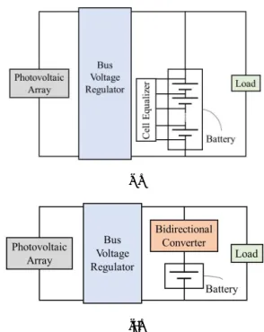
Vigorous research and development efforts for small scientific satellites are underway to realize frequent and low cost scientific space missions. Traditional power systems in scientific satellites employ un unregulated bus system where a secondary battery and load are directly connected, as illustrated in Fig. 1(a). The unregulated systems are advantageous over regulated bus systems [see Fig. 1(b)] from the viewpoint of the system simplicity as the number of power converters is only one. The number of battery cells connected in series is unambiguously determined by the load voltage requirement—e.g., 8 and 12 cells for 28- and 50-V bus systems, respectively. The energy capacity of the battery in watt-hour should be adjusted by selecting or manufacturing cells with a proper capacity, hence impairing the design flexibility. The poor design flexibility is quite unfavorable for small satellites to provide frequent mission opportunities.
Although the converter count is doubled, the regulated bus system is attractive from the viewpoint of battery design flexibility.
The number of battery cells connected in series can be arbitrary changed to meet the energy capacity demand, and even a single- cell battery system is theoretically feasible, as shown in Fig. 1(b) [1]. The cell equalizer is no longer necessary in the single-cell battery system, allowing the simplified system configuration. Although the single-cell battery system offers the flexible battery design and simplified system, challenges concerning to the bidirectional converters arise.
To bridge the huge voltage gap between the bus (50 V) and single-cell battery (3.0–4.2 V for lithium-ion cells), a bidirectional converter with a high conversion-ratio is necessary. Conventional nonisolated PWM converters for high conversion-ratio applications, however, are known to suffer from issues originating
from extreme duty cycle operations, such as increased losses and reduced controllability [2]. A current of the low-voltage side is more than 10 times than that of the high-voltage side, and therefore, an interleaving technique using multiple converters operating in parallel to mitigate current stresses is a favorable solution.
Conventional interleaved converters, however, require current sensors to match individual currents, increasing the cost and control complexity.
This paper proposes a novel bidirectional interleaved PWM converter with high voltage conversion-ratio and automatic current balancing capability. The fundamental characteristics were experimentally demonstrated using a 100-W prototype.
2. Proposed PWM Converter
2.1. Circuit Description and Voltage Conversion Ratio
The proposed PWM converter with high voltage conversion ratio Presented at the 37th ISAS Space Energy Symposium, March 5, 2018
(a)
(b)
Fig. 1. Satellite power systems based on (a) unregulated bus and (b) regulated bus with a single-cell battery.
This document is provided by JAXA.
is shown in Fig. 2. Although this circuit is the unidirectional version using diodes, it can be a bidirectional one by replacing diodes with switches. Three inductors, L1–L3, are connected to the battery and share the input current. Currents of these inductors are automatically balanced without feedback control, and therefore, no current sensors nor feedback loop are necessary. Three switches, inductors, and diodes operate in the interleaving manner 120° out of phase, and thus, this converter can be regarded as a three-phase interleaved converter when viewed from the battery side. Capacitors, C1 and C2, play two roles of high conversion ratio and automatic current balancing, as will be discussed later.
L1, Q1, and D1 operate as a boost converter that charges C1 to the voltage level of vC1 = Vbat/(1−d), where d is the duty cycle of switches. L2, Q2, and D2 also behave as a boost converter that together with C1 charges C2 to be vC2 = 2Vbat/(1−d). Similarly, L3, Q3, and D3 also form a boost converter, and its output voltage with vC2 is outputted to C3 or the load RL. The voltage conversion ratio of the proposed PWM converter is yielded as
Vbus Vbat
=
31ିd (1)
This conversion ratio is three times greater than that of the traditional PWM boost converter. The voltage conversion ratios of the proposed and conventional converters are compared in Fig. 3. For the 50-V bus system, the required voltage conversion ratio is 12.5–16.7 for a lithium-ion single cell with 3.0–4.2 V. Conventional converters need to operate with extremely high duty cycle of d > 0.9. The duty cycle range of the proposed converter, on the other hand, is reduced to around 0.8, avoiding the extreme duty cycle operations.
2.2. Operation Modes
The theoretical key operation waveforms and current flow Fig. 4. Key operation waveforms.
vgs1vDSvCiL
Time iinvgs2vgs3
Mode 1 3 1 4 1 2 1 3 1 4 dTS
iL1 iL2 iL3 vDS1 vDS2 vDS3
vC1
vC2 TS Fig. 2. Proposed PWM converter with high voltage conversion ratio (unidirectional).
Fig. 3. Theoretical voltage conversion ratios.
This document is provided by JAXA.
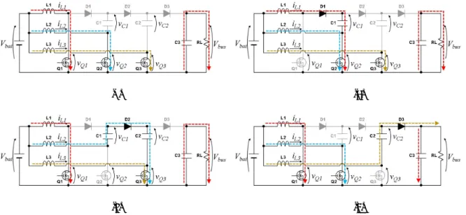
directions are shown in Figs. 4 and 5, respectively. Gating signals for Q1–Q3, vgs1–vgs3, are applied so that at least two of three switches are simultaneously on. vgs1–vgs3 are 120° out of phase for the interleaving operation. One switching cycle can be divided into 6 modes, but three of them are Mode 1, during which all switches are turned on.
Mode 1 [Fig. 5(a)]: vgs1–vgs3 are applied. All switches are on and their drain-source voltages, vDS1–vDS3, are zero. Inductor currents, iL1–iL3, linearly increase as Vbat is applied. The input current iin, which is the sum of iL1–iL3, also increases.
Mode 2 [Fig. 5(b)]: vgs1 is removed to turn off Q1. D1 starts to conduct, and iL1 linearly decreases. C1 is charged by iL1 and its voltage vC1 increases. Since one of inductor currents decreases, iin also decreases.
Mode 3 [Fig. 5(c)]: vgs2 is at low level to turn off Q2. D2 starts to conduct, and L2 discharges and its current iL2 decreases. iL2
together with C1 charge C2, and vC2 increases. Similar to Mode 2, iin
decreases due to the decrease in iL2.
Mode 4 [Fig. 5(d)]: Q3 is turned off, and D3 conducts. L3 and C2 charge C3.
2.3. Current Balancing Mechanism
All the inductor currents are assumed to be constant without ripple components. C1 is charged by iL1 during Mode 1 [Fig. 5(b)], and is discharged by iL2 during Mode 2 [Fig. 5(c)]. Meanwhile, C2 is charged and discharged by iL2 and iL3 during Modes 3 and 4, respectively, as shown in Figs. 5(c) and (d).
Assuming lengths of Modes 2–4 are identical, the charge conservation law for
C2 and C3 ensures the automatic current balancing for all inductors. This balancing mechanism does not rely on any active control or current sensing, and therefore, all inductor currents are passively balanced.
3. Experimental Results
A 100-W prototype of the proposed PWM converter was built, as shown in Fig. 6.
Fig. 6. Photograph of 100-W prototype.
Table 1. Component values.
(a) (b)
(c) (d)
Fig. 5. Current flow directions in (a) Mode 1, (b) Mode 2, (c) Mode 3, and (d) Mode 4.
This document is provided by JAXA.
Component values are listed in Table 1. The prototype was operated with Vbat = 4.0 V and Vbus = 50 V at the switching frequency of 100 kHz.
Measured current waveforms at the full load are shown in Fig.
7. Measured currents of iL1–iL3 were 120° out of phase, and their averages were identical, verifying the passive current balancing capability.
The measured voltage conversion ratio is compared with the theoretical one, as shown in Fig. 8. The experimental results matched satisfactorily with the theory. Slight mismatch was considered due to the power conversion loss in the prototype.
The measured power conversion efficiency is shown in Fig. 9.
The efficiency steadily decreased as the output power increased.
The efficiency at the full load of 100 W was as high as 90%.
4. Conclusions
The bidirectional PWM converter with high voltage conversion ratio and automatic current balancing capability has been proposed for single-cell battery power systems in small scientific satellites. The proposed converter operates in an interleaving manner, and the added capacitors realize not only high voltage conversion but also automatic current balancing.
The 100-W prototype was built, and its fundamental characteristics were experimentally demonstrated.
References
[1] M. Uno and A. Kukita, “Multi-port converter integrating boost and switched capacitor converters for single-cell battery power system in small satellite,” in Proc. IEEE ECCE-Asia Down Under, Jun. 2013, pp.
747–752.
[2] K. Yao, M. Ye, M. Xu, and F. C. Lee, “Tapped-inductor buck converter for high-step-down dc–dc conversion,” IEEE Trans. Power Electron., vol. 20, no. 4, pp. 775–780, Jul. 2005.
Fig. 8. Measured voltage conversion ratio.
30 25 20 15 10 5 Voltage Conversion Ratio 0
1.0 0.9
0.8 0.7
0.6
Duty Cycle Theory
Experiment Fig. 7. Measured current waveforms.
12 11 10 9 8 7
Current [A]
Time [5 µs/div]
iL1 iL2 iL3
Fig. 9. Measured power conversion efficiency 100
98 96 94 92 90 88
Efficiency [%]
100 80 60 40 20 0
Power [W]
This document is provided by JAXA.

![Fig. 9. Measured power conversion efficiency 100989694929088Efficiency [%] 100806040200Power [W] This document is provided by JAXA.](https://thumb-ap.123doks.com/thumbv2/123deta/6807558.2230296/4.892.481.769.375.584/measured-power-conversion-efficiency-efficiency-power-document-provided.webp)
