3-Port Converter Integrating a Boost Converter and Switched Capacitor Converter for a Single-Cell Battery Power System in a Small Satellite
Masatoshi Uno
1)and Akio Kukita
2)1)
ARD/JAXA, 2-1-1 Sengen, Tsukuba, Ibaraki, 305-8505 Japan
2)
ISAS/JAXA, 3-1-1 Yoshinodai, Sagamihara, Kanagawa prefecture, 252-5210 Japan
1. Introduction
Small satellites were previously regarded as educational tools for university students. However, their applications have been steadily expanding, from Earth observations to engineering demonstrations. The major advantages of small as opposed to large satellites include risk mitigation, cheaper development cost, and accelerated development, etc. However, since they are basically small, all components, including the power system, must also be constructed compactly and simply.
Building and testing batteries for such small satellites are daunting tasks for students and engineers since they usually involve retrofitting commercial batteries for terrestrial use which must withstand harsh space environmental conditions, such as the vacuum in space, radiation, and vibration during the rocket launch [1]. The power requirement for such small satellites is basically less than a few hundred watts. Therefore, batteries for small satellites include several small lithium-ion cells, each having a few ampere-hours, connected in series to meet the voltage requirement of a satellite bus. Although space-qualified lithium-ion batteries, which are rugged and radiation-tolerant, have been developed by manufacturers, these are usually for large satellites and too large for small satellites; with a nameplate capacity larger than several tens of ampere-hours [2]. Although even a single space-qualified lithium-ion cell is enough to cover the energy requirement of small satellites, a significant voltage gap between a single-cell (3.0–4.2 V) and bus voltage (14–28 V) must be bridged.
Bidirectional dc-dc converters with a high voltage-conversion ratio may be applicable for small satellite applications. However, to minimize the size of the power system, such bidirectional converters should be as compact and efficient as possible. In this paper, a 3-port converter integrating a boost converter and a switched capacitor converter is proposed for single-cell battery power systems in small satellites. With the proposed 3-port converter, the cell current and voltage are PWM-controlled by the boost converter, while a high voltage-conversion ratio is achieved by the switched capacitor converter.
2. 3-PORT CONVERTER INTEGRATING BOOST AND SWITCHED CAPACITOR CONVERTERS 2.1. Comparison between Traditional and Proposed Power Systems
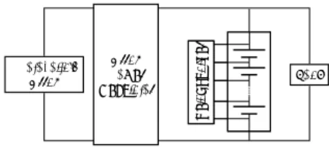
Traditional and proposed power systems for small satellites are compared in Fig. 1. In the traditional power system, shown in Fig. 1(a), the charging power from a photovoltaic (PV) array to a battery consisting of series-connected cells is controlled by a so-called array power regulator (APR). Loads are directly connected to the battery, hence the bus voltage is basically unregulated. In this traditional power system, since the battery consists of series-connected cells, a cell equalizer, which equalizes cell voltages to ensure years of safe operation, is necessary. Conversely, in the proposed power system shown in Fig.
1(b), the cell equalizer is no longer necessary because of its single-cell battery configuration, while the bus voltage is still unregulated, as explained in the next subsection. This means the power system can be simplified by eliminating the cell equalizer.
In addition, a space-qualified cell is likely to be used in the proposed power system. For example, four 5-Ah cells connected in series in the traditional power system can be replaced with a single 20-Ah cell in the proposed power system. 5-Ah cells are out Presented at the 32
ndISAS Space Energy Symposium, 1 March, 2013
This document is provided by JAXA
Photovoltaic
Array Load
Array Power Regulator
Cell EqualizerCell Equalizer
(a) Traditional unregulated power system using series-connected cells.
Photovoltaic
Array Multiport Load
Converter
(b) Proposed unregulated power system using a single-cell.
Fig. 1. Comparison between traditional and proposed unregulated power systems for small satellites.
L
Cin
Cout Vin
Qa Qb
VBoost VSN
(a) Synchronous boost converter.
Q5 Q6 Q7 Q8
C1 C2 C3 C4
Q1 Q2 Q3 Q4
C5 C6 C7
A
B
C
D
Vb
Va
(b) Switched capacitor converter.
Fig. 2. Key elements of the 3-port converter.
of range of space-qualified cells, while there are 20-Ah-class space-qualified cells in the market.
2.2. Circuit Description of a 3-Port Converter Integrating Switched Capacitor and Boost Converters
Various multi-port converter concepts have been proposed for renewable energy systems [3],[4]. The proposed 3-port converter is based on a combination of a synchronous boost converter and a switched capacitor converter, shown in Figs. 2(a) and (b), respectively. In the synchronous boost converter shown in Fig. 2(a), switches Q
aand Q
bare alternately driven, and the voltage at the switching node, V
SN, swings between V
inand V
Boost. Conversely, in the switched capacitor converter, odd- and even-numbered switches are alternately driven, and there are four switching nodes in this configuration ― nodes A–D. Ideally, the voltage of V
ais four times that of V
bin this example configuration
due to four capacitors, C
1–C
4, stacked in series.
Integrating the synchronous boost converter shown in Fig. 2(a) and the switched capacitor converter shown in Fig. 2(b) yields the proposed 3-port converter, as shown in Fig. 3. The inductor in the boost converter is tied to the switching node A in the switched capacitor converter, and switches Q
7and Q
8are shared. Either switching node can be used depending on the voltage relationship between V
inand V
Bus.
2.3. Control for Charging and Discharging Modes
In general, switched capacitor converters are basically unregulated;
voltage regulation is possible but significant power conversion loss is very likely [5]. However, since the switched capacitor converter is used alongside the boost converter, the cell current and voltage can be regulated with a PWM control.
In this configuration, since the single-cell battery is tied to C
1while the bus is connected to C
4, the ideal voltage relationship between cell voltage, V
Cell, and bus voltage, V
Bus, is
Cell
Bus
V
V = 4 . (1)
Ideally, the voltage of the switching node, V
SN, swings between 3 V
Celland 4 V
Cell, meaning the relationship among V
in, V
Cell, and V
Buscan be yielded as
4 4
Bus in Cell
V D
V V =
= − , (2)
where D is the duty cycle of the odd-numbered switches.
For the charging mode, either the cell voltage V
Cellor current I
Cellis PWM-controlled based on (2), while the bus voltage V
Busvaries arbitrarily according to (2). Accordingly, the boost converter controls the charge current and voltage while the switched capacitor converter achieves a high voltage-conversion ratio. For a discharging mode, conversely, no control is necessary; switches are operated with a fixed duty cycle of 50%.
In this paper, a switched capacitor converter consisting of four capacitors stacked in series, C
1–C
4, is shown as an example. By changing the number of
This document is provided by JAXA
Q5 Q6 Q7 Q8
Vin Cin RL L
C1 C2 C3 C4
Q1 Q2 Q3 Q4
C5 C6 C7
VCell ICell iL
IBus
VBus
VCell VSN
Iin
Switched Capacitor Converter Boost Converter
Fig. 3. 3-port converter integrating boost and switched capacitor converters.
Fig. 4. A photograph of a 20-W prototype.
100 95 90 85 80
Efficiency [%]
25 20 15 10 5 0
Power [W]
18.0 17.5 17.0 16.5 16.0 VBus [V]
1.2 0.8 0.4 0.0 ICell, IBus [A]
ICell
I
B us VC ell = 4.1 V
90 85 80 75 70
Efficiency [%]
10 8 6 4 2 0
Power [W]
17 16 15 14 13 VBus [V]
3.0 2.0 1.0 0.0 ICell, IBus [A]
IB us IC ell
V C ell = 4.1 V
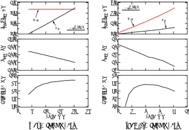
(a) Charging mode. (b) Discharging mode.
Fig. 5. Measured power conversion efficiencies and bus voltage characteristics.
series-stacked capacitors, the voltage ratio of V
Busto V
Cellcan be arbitrarily adjusted. Generally, the voltage of lithium-ion cells varies within the range 3.0–4.1 V. According to (1), the variation range of the bus voltage is expected to be 12.0–16.4 V. The proposed 3-port converter shown in Fig. 3 is considered suitable for 14-V unregulated systems where the bus voltage varies between approximately 11–17 V.
For higher/lower bus voltage power systems, the number of series-stacked capacitors in the switched capacitor converter should be increased/decreased to obtain suitable voltage relationships among V
in, V
Cell, and V
Bus.
3. EXPERIMENTAL RESULTS
3.1. Prototype and Efficiency Measurement
A 20-W prototype of the proposed 3-port converter was built as shown in Fig. 4.
Ceramic capacitors with capacitance of 44 µF and N-Ch MOSFETs (RJK0329DPB, R
on= 1.8 mΩ) were used for C
1–C
7and Q
1–Q
8in the switched capacitor converter. The inductance of L was 10 µH. The prototype was operated at a switching frequency of 100 kHz. For a battery charging mode, the current and voltage of I
Celland V
Cellwere PWM-controlled with a constant current–constant voltage (CC–CV) charging scheme of 1.0 A–4.1 V. For a battery discharging mode, duty cycles for odd- and even-numbered switches are fixed at 50%.
The measured power conversion efficiencies and bus voltage characteristics for charging and discharging modes are shown in Figs. 5(a) and (b), respectively. The charging mode was measured when V
Cell= 4.1 and I
Cell= 1.0 A. As the power rose with increasing I
Bus, V
Busdecreased, which implies that the conversion loss rose with increasing power and I
Bus. Power conversion efficiency as high as 97% was achieved at 20 W. For a discharging mode, conversely, the measured power conversion efficiency was lower than that for the charging mode, with peak efficiency of about 84.5%. In discharging mode, since power from the cell had to traverse capacitors and switches in the switched capacitor converter before reaching the bus, the collective loss in each component was considerable.
Thus, high efficiency was relatively easily achieved for the charging mode, whereas further improvement is preferable for the discharging mode. To achieve positive power system performance, the round-trip efficiency, which is defined as a product of efficiencies for charging and discharging, should be improved. These experimental results imply that the proposed multi-port converter should be designed with particular focus on discharging modes to improve round-trip efficiency.
3.2. Experimental Charge-Discharge Cycling A lithium-polymer cell with capacity of 2200-mAh
This document is provided by JAXA
4.2 4.0 3.8 3.6 3.4 3.2 3.0 VCell [V]
270 180
90 0
Time [min]
-2 -1 0 1 2
ICell [A]
18 16 14 12 10 VBus [V]
1.5
1.0
0.5
0.0 IBus, Iin [A]
VCell
ICe ll
IBus Iin
VB us