九州大学学術情報リポジトリ
Kyushu University Institutional Repository
強度増強された自立ナノ膜の開発
アンテネ, キンドゥ, メルシャ
http://hdl.handle.net/2324/2236194
出版情報:Kyushu University, 2018, 博士(工学), 課程博士 バージョン:
権利関係:
Development of Mechanically Reinforced Free-standing Nanomembranes
Anteneh Kindu Mersha
Department of Chemistry and Biochemistry Graduate School of Engineering
KYUSHU UNIVERSITY
2019
Table of contents
Chapter 1 General Introduction 1
1.1 Free-standing nanomembranes 1
1.2 Fabrication of free-standing nanomembranes 1
1.3 Challenges in developing functional free-standing nanomembranes 3
1.4 Mechanical enhancement in nanomembranes 4
1.4.1 Nanoparticle filler approach 5
1.4.2 Molecular level approaches 5
1.5 Motivation and summary of the thesis 6
1.6 References 9
Chapter 2 Preparation of large, ultra-flexible and free-standing nanomembranes of metal oxide/polymer composite and their gas permeation properties 12
2.1 Introduction 13
2.2 Experimental 16
2-2-1. Materials 16
2-2-2. Nanomembrane preparation 16
2-2-3. Gas permeation experiment 17
2.3 Results and discussion 20
2.3.1 Definition of important terms 20
2.3.2 Membrane design 20
2.3.3 Film growth monitoring, morphological and mechanical properties 21
2.3.4 Gas permeation property 23
2.4 Discussion 24
2.5 Conclusion 25
2.6 References 26
Chapter 3 Metal oxide/polymer blends for the preparation of free-standing
nanomembranes and their gas permeation properties 27
3.1 Introduction 28
3.2 Experimental 30
3-2-1. Materials 30
3-2-2. Nanomembrane preparation 30
3-2-3. Gas permeation experiment 31
3.3 Results and discussion 33
3.3.1 Membrane material selection and preparation conditions 33
3.3.2 Morphological and mechanical properties 34
3.3.3 Gas permeation property 36
3.4 Discussion 38
3.5 Conclusion 39
3.6 References 40
Chapter 4 Mechanical reinforcement of free-standing nanomembranes via incorporation
of aluminosilicate nanotubes 41
4.1 Introduction 42
4.2 Experimental 45
4.2.1 Materials 45
4.2.2 Synthesis of ASNTs 49
4.2.3 Nanomembrane preparation procedure 49
4.2.4 Membrane characterization 47
4.2.5 Investigation of mechanical properties 48
4.2.6 Gas permeation experiment 48
4.3 Results and discussion 49
4.3.1 ASNTs synthesis and characterization 49
4.3.2 Nanomembrane design 50
4.3.3 Nanomembrane preparation, morphology and structural analysis 51
4.3.3.1 Scaffold preparation 51
4.3.3.2 Polymer coating 53
4.3.4 Investigation of mechanical properties 56
4.3.4.1 Physical manipulation 56
4.3.4.2 Bulging test 57
4.3.4.3 Estimation of elastic modulus 63
4.3.4.4 LBL assembly of ASNT/PDMS as alternative approach 66
4.3.5 Gas separation property 67
4.4 Discussion 68
4.5 Conclusion 69
4.6 References 70
Chapter 5 Summary and outlook 73
References 75
Acknowledgement
Chapter 1 General Introduction 1.1 Free-standing nanomembranes
Following the Richard Feynman’s 1959 lecture ‘There’s Plenty of Room at the Bottom’, which challenged the science community to think small, the field of nanotechnology is now maturing rapidly with the fabrication of unique or enhanced materials, products and devices.1,2
Nanomembranes are important class of nanotechnology, with significantly advancing applications in a wide range of areas including molecular separations,3–6 energy conversion and storage,7–10 sensing,11,12 catalysis13 and biomedical applications,12,14 owing to their nanometer thickness and large lateral dimensions. A nanomembrane comprise thicknesses of less than a few hundred nanometers and minimum lateral dimensions of at least two orders of magnitude larger than the thickness.7,12 Free-standing nanomembranes (FS-NMs) are defined as self-supporting nanomembranes with dual surfaces that can physically separate two spaces,15,16 by sustaining their size and shape without support.17,18
FS-NMs offer unique advantages that are difficult (or otherwise impossible) to achieve using their bulk analogues and other material forms because of the following features. (i) despite their nano- thickness, FS-NMs can be transferred onto any arbitrary substrate of diverse configurations such as planar, curvilinear or wavy structures.7,12,19 Such properties allow the design of devices which cannot be achieved with conventional technologies that rely on rigid, planar materials. For example, a human eye-inspired hemispherical imaging devices present practical routes for integrating well- developed planar device technologies (such as semiconductor wafers) onto the surfaces of complex curvilinear objects.20 (ii) They have high size to thickness aspect ratio of greater than 106.15 (iii) FS-NMs have unique interfacial and mechanical properties, including noncovalent adhesiveness, flexibility and high molecular flux for separation.15,21 (iv) They also provide opportunities for dual surface functionalization in applications such as solid-electrolytes for batteries.
1.2 Fabrication of freestanding nanomembranes
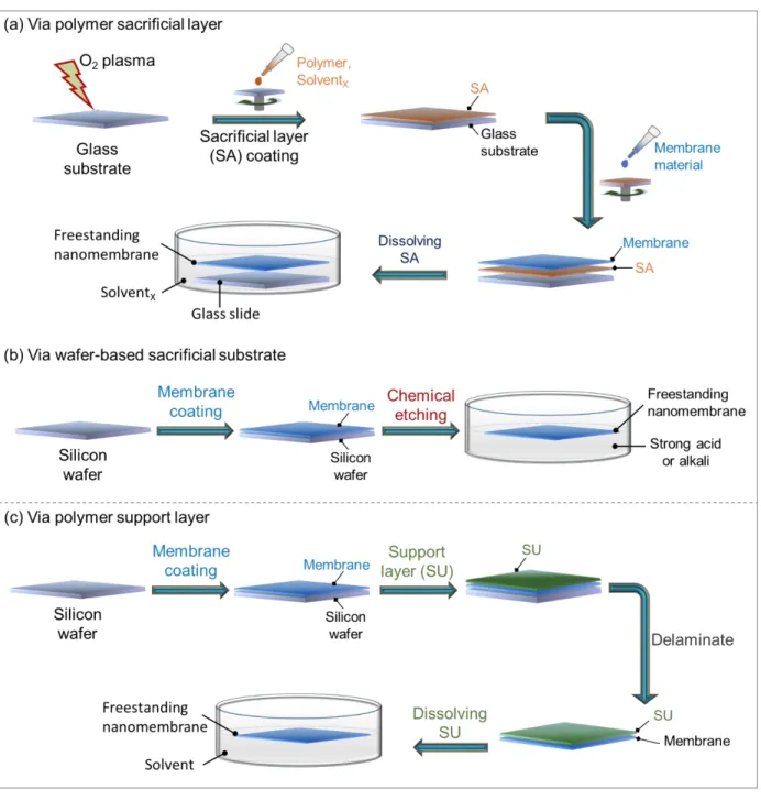
Preparation of nanomembranes with self-supporting nature is not an easy task since it requires careful release and handling of the nanomembrane from the substrate without damage. There are two methods to fabricate FS-NMs; sacrificial layer and support layer approaches, as illustrated in Figure 1-1. In the sacrificial layer approach, two possible substrates can be employed; A polymer
pre-coated on a solid substrate such as glass (Figure 1-1a) that can be dissolved in a particular solvent or a silicon wafer which can be etched by strong acid or alkaline solution (Figure 1-1b).
Figure 1-1. Schematic illustration of FS-NM preparation procedures. (a) Via polymer sacrificial layer: it is a commonly used approach, and applicable to the majority of nanomembrane deposition techniques. (b) Via wafer-based sacrificial substrate: it is generally used for the preparation of polymeric FS-NMs which are stable in strong acid/alkaline solution. (c) Via polymer support layer:
it is often utilized in the fabrication of metallic and metal oxide FS-NMs. In the current study, polymer sacrificial layer approach using poly(4-vinyl phenol) was employed.
In either case, the nanomembrane material is deposited on the sacrificial layer by various techniques such as spin coating, dip coating, spray coating, spin/dip/spray-assisted layer-by-layer assembly,22 Langmuir–Blodgett,23 as well as chemical and physical vapor depositions. Spin- coating is a versatile method to prepare ultrathin membranes as it allows the deposition of highly ordered nanostructures with prediction and control of precise film thickness and surface roughness.24
Once the nanomembrane is prepared, the sacrificial layer is selectively removed by dissolution or chemical etching, releasing the self-supporting nanomembrane (Figure 1-1a, b). There is no special requirement for a sacrificial layer material, however, it should have smooth surface and should be readily soluble in a particular solvent.
In the case of support layer approach (Figure 1-1c), the nanomembrane material is first coated on a solid substrate followed by thick supporting layer. Afterwards, the weakly adhered nanomembrane is peeled off from the solid substrate together with the support. Eventually, the support layer is removed by selective dissolution in a suitable solvent, which releases the FS-NM floating on the surface.
At this stage, the nanomembrane could be ready for the desired function. It can be transferred onto other substrates while in the detachment solvent or it can be lifted off and mounted onto a preferred surface for use.
1.3 Challenges in developing functional freestanding nanomembranes
To be used for a specific purpose, nanomembranes should satisfy some essential requirements;
self-supporting nature, mechanical strength and defect or crack freeness (Figure 1-2). The merits of nano-scale thickness and free-standing nature have been explained in the previous section. The need for mechanical strength in nanomembranes and enhancement methods are discussed in the following section. Along with mechanical robustness is prevention of defects that can possibly be generated either during the film preparation step or during processing steps such as detachment, transfer onto other substrates and usage-related stress.
Figure 1-2. Required parameters in designing FS-NMs.
1.4 Mechanical enhancement in nanomembranes
The fabrication of nanomembranes for diverse applications is an established technology. However, only little effort has been put to resolve their mechanical property issues. To fully utilize the appealing features of FS-NMs in a wide range of applications, they need to have sufficient mechanical and chemical stabilities in the macroscopic scale. For example, due to their ultrathinness, FS-NMs are expected to enhance mass transport with less energy in separation applications. However, membrane thinning is often encountered by mechanical weakening.25 Also, excellent mechanical stability of FS-NMs is highly desired in practical applications such as wound- dressing, antibacterial therapeutics and cellular organization scaffolding,12 where FS-NMs are installed onto uneven surfaces.
Therefore, macroscopic mechanical reinforcement is a critical research challenge in the development of FS-NMs. Generally, the mechanical property problem in nanomembranes is originated from the inherent properties of materials, meaning that polymers are too soft25 and inorganic materials are too fragile.26 Thus, combining these two materials has been considered as a straightforward approach to develop composite materials with synergetic mechanical enhancement. Some of the strategies are discussed in the following sub-sections.
1.4.1 Nanoparticle filler approach
Incorporation of inorganic fillers into a polymer matrix27–30 is a conventional approach for the preparation of mechanically reinforced organic/inorganic composite materials. Thus, nanocomposite membranes are consisted of micro- or nanoscale inorganic particles as the discrete phase and a polymeric material as a continuous or matrix phase31 (Figure 1-3). Rigid nanoparticles such as metals,28 metal oxides,31 zeolites,32 nanofibers such as carbon nanotubes (CNTs)33 and nanosheets such as graphene34 are frequently used fillers.
One dimensional materials such as CNTs33,35,36 and metal oxide-based aluminosilicate naotubes (ASNTs),37,38 are interesting class of reinforcements with high aspect ratio. They can form networked structures in a membrane that can act as a framework to anchor soft organic polymers.
Such continuous fiber structures also resist crack propagation in ultrathin films.39,40
The mechanical properties of filler-reinforced membranes generally increase with increasing nanofiller loading at low volume fractions but then decrease at higher filler fractions due to issues related to agglomeration.34 Large fillers and agglomerations flaw surface of the nanomembranes.
This, in turn, strains stress movement (Figure 1-3), and eventually decreases tensile strength.
Figure 1-3. Schematic representation of inorganic fillers in a polymer matrix, and effect of agglomerations in mechanical properties.
1.4.2 Molecular level approaches
In the case of molecular level designs such as organic/inorganic interpenetrating networks,41 crosslinked hard polymers42 and layer-by-layer assembly,18,22 the membrane materials are allowed to interact at the molecular or atomic scale. Such molecular level integration facilitates the development of ultrathin yet mechanically enhanced FS-NMs. These procedures often require materials to satisfy both the properties of membrane formation ability and functional moieties in a membrane form, limiting the range of material selection.
1.5 Motivation and summary of the thesis
Self-supporting nanomembranes are no longer theoretical and experimental curiosity, and are recognized as efficient nanomaterials for various applications, including membrane separations, electrolytes in energy storage and conversion, sensors and scaffolds for cellular and nanoparticle organization. However, attempts to develop highly compliant FS-NMs with unprecedented macroscopic mechanical stabilities remained a research challenge. Thus, the aim of the present dissertation is to address the toughing of FS-NMs which is essential for practical applications.
In the course of this research, an effort has been put to develop a facile strategy for the preparation of free-standing and mechanically strong, yet functional nanomembranes. Organic/inorganic composite materials are the subject of this research as they pave the way to synergetic mechanical reinforcement by combining the flexibility of polymers and rigidity of inorganics. The developed nanomembranes were tested for gas separation, which is among the most complex molecular separation processes due to its hypersensitivity to leakage. The main achievements of the research work are outlined as follows.
Firstly, a general introduction has been presented (Chapter 1) on the emergence of nanotechnology, the properties and advantages of nanomembranes, requirements to nanomembrane development, as well as mechanical enhancement strategies.
In Chapter 2, a sol-gel induced LBL assembly of metal oxide/polymer composite nanomembrane (Figure 1-4) is discussed. The spin-assisted LBL assembly of poly(vinyl alcohol) (PVA) and TiO2
was aimed to maximize the synergetic mechanical enhancement between the polymer and metal oxide via strong sol-gel reactions. Accordingly, a few tenths nm thick, large size, highly flexible and free-standing nanomembrane was developed.
Figure 1-4. PVA/TiO2 layer-by-layer nanomembrane. (a) Digital image of large-size, ca. 10 cm2, nanomembrane floating on ethanol. (b) Aspiration and release process into a 2 mm diameter micropipette; the membrane retained its shape and size after the process. (c) SEM image of the nanomembrane transferred onto a porous support, Inset: Schematic illustration of the vertical membrane structure.
However, the membrane demonstrated low preferential separation of gas mixtures. The little or no selective transport could be due to the formation of pinholes either during membrane preparation or processing steps. This, in turn, would mainly be associated to the hard nature of PVA, which didn't soften the oxide phase sufficiently in the composite nanomembrane.
To overcome the low selective separation (which might reflect unsatisfactory mechanical stability) of the PVA/TiO2 LBL nanomembrane, two measures were investigated (Chapter 3); (i) choosing a softer polymer with CO2 selective properties, and (ii) changing the membrane architecture.
Although no significant mechanical property enhancement was observed, compared to the PVA/TiO2, the prepared PEG-OH/SiO2 hybrid nanomembrane (Figure 1-5) demonstrated improved CO2/N2 selectivity.
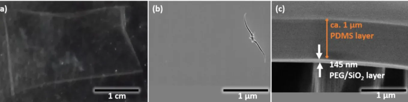
Figure 1-5. (a) Digital image of the nanomembrane in the detachment solvent. (b,c) SEM image of bare PEG/SiO2 nanomembrane transferred onto a porous support; (c) after caulking layer coating to prevent leakage during gas separation experiment. Scale bar
The obtained results in Chapter 2 and Chapter 3 implied that it is not smooth to improve mechanical property of a nanomembrane while maintaining the separation performance or vice versa only by changing membrane materials. In fact, there can be a probability to tune both mechanical property and function together. It would, however, be time consuming and costly to search for the best material combinations. Therefore, a more reliable membrane architecture and preparation method was sought.
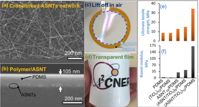
Accordingly, an unconventional design approach that integrates macroscopic mechanical stability together with tunable membrane functions was developed and presented in Chapter 4. This unique strategy involves the incorporation of aluminosilicate nanotube (ASNT) network structure (Figure 1-6a) as a bed scaffold to deposit polymeric membranes. Unlike amorphous metal oxides, aluminosilicate nanotubular oxide scaffolds brought about a dramatic enhancement in the mechanical property of the composite nanomembrane with polydimethylsiloxane (PDMS). A four- fold increase in the tensile strength and over 43 times higher biaxial modulus was observed compared to the pristine PDMS (Figure 1-6e,f).
Figure 1-6. (ASNT/TiO2)n/PDMS nanomembrane. (a–d) Morphology and macroscopic manipulation. (e,f) Comparison of mechanical properties of pristine and scaffolded PDMS, confirming that ASNT networks brought about significant mechanical property enhancements.
Finally, summary and future prospect of the achievements of the study are provided in Chapter 5.
The results section of each chapter is followed by a conceptual discussion. The dissertation presented a significant step-forward to the realization of ultrathin and free-standing, yet macroscopically tough advanced membranes for practical applications such as small molecule separation.
References
(1) Schummer, J. Nat. Nanotechnol. 2016, 11 (10), 828–834.
(2) Maynard, A. D.; Aitken, R. J.; Butz, T.; Colvin, V.; Donaldson, K.; Oberdörster, G.;
Philbert, M. A.; Ryan, J.; Seaton, A.; Stone, V.; Tinkle, S. S.; Tran, L.; Walker, N. J.;
Warheit D. B. Nature 2006, 444 (7117), 267–269.
(3) Wang, L.; Boutilier, M. S. H.; Kidambi, P. R.; Jang, D.; Hadjiconstantinou, N. G.; Karnik, R. Nat. Nanotechnol. 2017, 12 (6), 509–522.
(4) Lindemann, P.; Tsotsalas, M.; Shishatskiy, S.; Abetz, V.; Krolla-Sidenstein, P.; Azucena, C.; Monnereau, L.; Beyer, A.; Gölzhäuser, A.; Mugnaini, V. Chem. Mater. 2014, 26 (24), 7189–7193.
(5) Gupta, Y.; Hellgardt, K.; Wakeman, R. J. J. Memb. Sci. 2006, 282 (1–2), 60–70.
(6) Schuster, C.; Rodler, A.; Tscheliessnig, R.; Jungbauer, A. Sci. Rep. 2018, 8 (1), 1–11.
(7) Rogers, J. A.; Lagally, M. G.; Nuzzo, R. G. Nature 2011, 477 (7362), 45–53.
(8) Liu, X.; Si, W.; Zhang, J.; Sun, X.; Deng, J.; Baunack, S.; Oswald, S.; Liu, L.; Yan, C.;
Schmidt, O. G. Sci. Rep. 2015, 4 (1), 7452.
(9) Li, Z.; Ma, G.; Ge, R.; Qin, F.; Dong, X.; Meng, W.; Liu, T.; Tong, J.; Jiang, F.; Zhou, Y.
Angew. Chem. Int. Ed. 2016, 55 (3), 979–982.
(10) Liu, Q.; Fujigaya, T.; Cheng, H.-M.; Nakashima, N. J. Am. Chem. Soc. 2010, 132 (46), 16581–16586.
(11) Jiang, C.; Markutsya, S.; Pikus, Y.; Tsukruk, V. V. Nat. Mater. 2004, 3 (10), 721–728.
(12) Fujie, T. Polym. J. 2016, 48 (7), 773–780.
(13) Lu, X.; Yin, Y.; Zhang, L.; Xi, L.; Oswald, S.; Deng, J.; Schmidt, O. G. Nano Energy 2016, 30, 69–76.
(14) Fujie, T.; Ahadian, S.; Liu, H.; Chang, H.; Ostrovidov, S.; Wu, H.; Bae, H.; Nakajima, K.;
Kaji, H.; Khademhosseini, A. Nano Lett. 2013, 13 (7), 3185–3192.
(15) Watanabe, H.; Vendamme, R.; Kunitake, T. Bull. Chem. Soc. Jpn. 2007, 80 (3), 433–440.
(16) Cheng, W.; Campolongo, M. J.; Tan, S. J.; Luo, D. Nano Today 2009, 4 (6), 482–493.
(17) Huang, G.; Mei, Y. Adv. Mater. 2012, 24 (19), 2517–2546.
(18) Mersha, A.; Selyanchyn, R.; Fujikawa, S. CleanE 2017, 1 (1), 80–89.
(19) Kim, D.; Rogers, J. A. ACS Nano 2009, 3 (3), 498-501.
(20) Ko, H. C.; Stoykovich, M. P.; Song, J.; Malyarchuk, V.; Choi, W. M.; Yu, C. J.; Geddes,
J. B.; Xiao, J.; Wang, S.; Huang, Y. Nature 2008, 454 (7205), 748–753.
(21) Vandezande, P.; Gevers, L. E. M.; Vankelecom, I. F. J.; Koros, W. J.; Ma, Y. H.;
Shimidzu, T.; Loeb, S.; White, L. S.; Wildemuth, C. R.; Stafie, N. Chem. Soc. Rev. 2008, 37 (2), 365-405.
(22) Richardson, J. J.; Bjornmalm, M.; Caruso, F. Science 2015, 348 (6233), 2491.
(23) Miyano, K.; Mori, A. Thin Solid Films 1989, 168 (1), 141–149.
(24) Cho, J.; Char, K.; Hong, J. D.; Lee, K.-B. Adv. Mater. 2001, 13 (14), 1076–1078.
(25) Koros, W. J. Macromol. Symp. 2002, 188(1), 13-22.
(26) Vendamme, R.; Onoue, S.Y.; Nakao, A.; Kunitake, T. Nat. Mater. 2006, 5 (6), 494–501.
(27) Dong, G.; Li, H.; Chen, V. J. Mater. Chem. A 2013, 1 (15), 4610.
(28) Markutsya, S.; Jiang, C.; Pikus, Y.; Tsukruk, V. V. Adv. Funct. Mater. 2005, 15 (5), 771–
780.
(29) Zhu, X.; Tian, C.; Do-Thanh, C. L.; Dai, S. ChemSusChem 2017, 10 (17), 3304–3316.
(30) Rajan, G. S.; Sur, G. I. L. S.; Mark, J. E.; Schaefer, D. W.; Beaucage, G. J. Polym. Sci.
Part B Polym. Phys. 2003, 41, 1897–1901.
(31) Hosseini, S. S.; Li, Y.; Chung, T. S.; Liu, Y. J. Memb. Sci. 2007, 302 , 207–217.
(32) Mahajan, R.; Burns, R.; Schaeffer, M.; Koros, W. J. J. Appl. Polym. Sci. 2002, 86 (4), 881–890.
(33) Roy, N.; Sengupta, R.; Bhowmick, A. K. Prog. Polym. Sci. 2012, 37 (6), 781–819.
(34) Bhattacharya, M. Materials 2016, 9 (4), 1–35.
(35) Loos M. Fundamentals of polymer matrix composites containing CNTs. In Carbon Nanotube Reinforced Composites; Elsevier: Amsterdam, The Netherlands, 2015; pp.
125–170.
(36) Liu, T.; Fan, W.; Zhang, C. Polym. Nanotub. Nanocomposites Synth. Prop. Appl. Second Ed. 2014, 239–277.
(37) Kim, W. gwi; Nair, S. Chem. Eng. Sci. 2013, 104, 908–924.
(38) Kang, D. Y.; Lydon, M. E.; Yucelen, G. I.; Jones, C. W.; Nair, S. ChemNanoMat. 2015, 1 (2), 102-108.
(39) Mersha, A.; Fujikawa, S. ACS Appl. Polym. Mater. 2019, 1 (2), 112–117.
(40) Loos M. Composites. In Carbon Nanotube Reinforced Composites; Elsevier:
Amsterdam, The Netherlands, 2015; pp. 37–72.
(41) Vendamme, R.; Onoue, S.-Y.; Nakao, A.; Kunitake, T. Nat. Mater. 2006, 5 (6), 494–501.
(42) Watanabe, H.; Kunitake, T. Adv. Mater. 2007, 19 (7), 909–912.
Chapter 2 Preparation of large, ultra-flexible and free-standing nanomembranes of metal oxide/polymer composite and their gas permeation properties
Abstract
In this chapter, fabrication of free-standing nanomembrane of metal oxide (MOx) and polymer by spin-assisted layer-by-layer (LBL) assembly is discussed. Although there are research works on the fabrication of free-standing nanomembranes, development of such membranes with sufficient macroscopic properties (to withstand mechanical stress) for applications such as separation remained a challenging task. By combining the flexibility of organic polymers and the rigidity of molecular networks in inorganic materials, a few tens nm thick, large size, highly flexible and free- standing composite nanomembrane was developed. Synergetic mechanical reinforcement was realized via sol-gel induced molecular level LBL assembly of MOx and polymer. The nanomembrane sustained mechanical stability even after transfer onto a porous support for separation experiment. The electron microscopy observation proved no crack formation during nanomembrane fabrication and manipulation steps.
2.1 Introduction
Organic polymeric materials have been widely investigated in the fabrication of membranes, including scale up to industrial level, to take advantages of their flexibility and solution processability.1 From application viewpoint, thin membranes provide several advantages such as low molecular transport resistance, thereby increase separation efficiency. But thinning polymeric membranes is often encountered by mechanical weakening which leads to defect formation as well as handling difficulty. Inorganic materials, on the other hand, are hard and brittle. They become highly fragile when processed into nanofilms.1,2 Thus, combining organic and inorganic materials allows to integrate the flexibility of organic polymers and the rigidity of inorganic networks. The general properties of organic and inorganic materials with respect to membrane formation tendency are summarized in Figure 2-1. In addition to synergetic mechanical enhancement, organic/inorganic composite materials also offer distinct properties different from simple sums of original polymers and inorganics.3
Figure 2-1. General comparison of organic and inorganic materials in regard to their tendency to form membranes.
Mechanically reinforced composite membranes are often prepared in either of two ways; (i) introduction of inorganic filler particles in to a polymer matrix or (ii) molecular level integration of organic and inorganic components. Incorporation of inorganic fillers such as metal oxides, and nanofibers into a polymer matrix4–6 is a conventional method for improving mechanical property of polymeric membranes. In this approach, inorganic nanoparticles are introduced into the polymer solution prior to membrane formation. However, due to the likelihood of interfacial void formation,
Polymers Inorganics
Flexible Manipulation / processability Fragile
Weak chains Freestanding film formation Defect problem
Scalable Scalability Difficult
low Modulus High
low Thermal stability High
such as plastic deformation4, this method requires careful control of polymer−filler compatibility for suitable interfacial interactions and consequent membrane stability. Thus, it is still a crucial research task for the realization of defect-free membranes.4,7,8
In the second approach, molecular level designs such as organic/inorganic interpenetrating networks3 and layer-by-layer (LBL) assembly9 opened up opportunities for molecular level aggregation of membrane materials. Unlike to filler approach, such architectures allow higher proportion of organic/inorganic interaction sites, leading to a well-fused composite structure that enables the preparation of ultrathin and yet mechanically enhanced membranes. In addition to mechanical property improvement, incorporation of rigid inorganic structures into the polymer matrix creates molecular transport pathways4, improving molecular flux. Furthermore, compositing organic and inorganic materials advances thermal stability,10 allowing the deployment of such membranes at elevated temperature conditions.
Metal oxide (MOx) and polymer composites are among the most promissing combinations to develop mechanically enhanced free-standing nanomembranes (FS-NMs). Spin-assisted LBL assembly, which was introduced by Kookheon Char’s group,11 is a suitable technique to adsorb metal oxide and polymer materials through chemisorption. The MOx precursor and polymer phases undergo sol-gel reaction at the interface of alternate ultrathin coatings, leading to well-fused composite structure. The spin-assisted assembly yields a highly ordered internal structure via rearrangement of molecular chains and desorption of weakly bound chains. This simple technique allows multitude of membrane material selection, in part because it creates a platform to combine materials even from incompatible solvent solutions. Precise film thickness and surface roughness can also be controlled in molecular scale precision.
The general chemical reaction during sol–gel process can be described by the following three equations.12
−M−OR + H2O → −M−OH + ROH Hydrolysis (i)
−M−OH + M−OR → −M−O−M− + ROH Condensation (ii)
−M−OH + −M−OH → −M−O−M− + H2O Condensation (iii)
In this chapter, the preparation of an ultrathin, large size composite nanomembrane by spin- assisted alternate chemisorption of molecular layers of TiO2 and poly(vinyl alcohol) (PVA) has been discussed. Although LBL assembled polymer/inorganic composite films have been
investigated before,3,13 this work presents essential features, including free-standing nature coupled with pin-hole freeness as confirmed by gas permeation test. To the best of my knowledge, experimental demonstration of gas permeation using such free-standing MOx/polymer composite nanomembranes have not been studied.
2.2 Experimental Section 2.2.1 Materials
Soda lime glass was used as substrate for membrane preparation. Poly(4-vinylphenol) (PVP, Mw=11000, Sigma-Aldrich) was used as sacrificial layer. Poly (vinyl alcohol) (Mw=78000, 88 mol % hydrolyzed, Polysciences, Inc.) was used as polymer layer precursor. Titanium n-butoxide (Ti(OnBu)4, Gelest Inc.) was used as metal oxide precursor. Ethanol (EtOH, anhydrous, EMSURE, Germany) and toluene (Wako Co., Ltd.) were used as received. Deionized water (18.3 M cm−1, Millipore, Direct-QTM) was used for rinsing and solution preparation.
2.2.2 Nanomembrane preparation
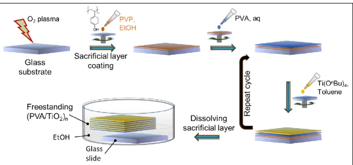
The FS-NMs preparation process is illustrated schematically in Figure 2-2. It involves three steps;
(i) sacrificial layer coating, (ii) LBL membrane assembly and (iii) membrane detachment by selective dissolution of the sacrificial layer.
Firstly, a glass substrate was sonicated in EtOH for about 60 min, rinsed by deionized water, dried by air-blowing and treated with oxygen plasma (FA-1, SAMCO, Japan, RF power: 55 W, the flow rate of oxygen: 10 sccm, chamber pressure: 20 Pa) for 4 min to make the substrate surface hydrophilic. Water contact angle after O2 plasma etching is < 10º. Afterwards, a 15 wt% EtOH solution of PVP was spin-coated (3000 rpm, 60 sec) on the glass substrate and heated at 120 C for 5 min.
Once cooled down to room temperature, an aqueous solution of PVA (0.3 wt %) was deposited (3000 rpm, 2 min) on the sacrificial layer, and allowed to dry in ambient air for 1 hour. The PVA coating introduces hydroxyl groups that are essential for the formation of well-integrated sreucture with metal oxide.14 Then, a Ti(OnBu)4 solution (50 mM, in toluene) was spin coated (3000 rpm, 2 min) and left in an ambient air for 30 min to allow hydrolysis and condensation. This alternate sol- gel deposition cycle of PVA and TiO2 was repeated until the desired film thickness.
PVA/TiO2 film growth during the repetitive process was monitored by parallelly preparing the LBL film on a quartz plate, and measuring UV/Vis absorption (Jasco V-670) after each deposition cycle.
Lastly, the glass substrate was immersed in EtOH to dissolve the sacrificial PVP layer and release the self-supporting nanomembrane. The detached film was freely floating in the sub-surface of EtOH solution.
Figure 2-2. Schematic representation of nanomembrane fabrication process by spin-assisted LBL assembly.
Film thickness and surface morphology were observed by field emission scanning electron microscope (FE-SEM, Hitachi S-5200). Specimen for SEM observation was prepared by transferring the nanomembrane onto anodized porous alumina (Anodisc, G.E. Healthcare) support.
2.2.3 Gas permeation experiment
In order to evaluate gas permeation, nanomembranes were transferred onto a porous alumina support. In fact, any porous support can be employed as long as its surface is smooth in order to prevent the nanomembrane from damage. After that, membrane area (space through which gas molecules pass) was limited by Kapton and alumina tapes with the open hole of 1 cm diameter as shown in Figure 2-3a. Subsequently, it was placed in the membrane cell (Figure 2-3b) to test gas permeation.
Gas permeation was measured using a commercial instrument (GTR-11A/31A system, GTR Tec Corp., Japan) coupled to gas chromatography, and the overall experimental setup is described schematically in Figure 2-3b. A mixed gas was introduced to the feed side of the membrane cell at room temperature. The pressure of the feed gas was set at 100 kPa as a gauge pressure, whilst
the permeate side was maintained in vacuum condition, resulting in a total pressure difference of ca. 200 kPa. The volume of gas passed through the membrane per unit time was measured by gas chromatography.
Figure 2-3. A schematic illustration of (a) nanomembrane assembly for gas permeation experiment, (b) gas permeance measurement apparatus.
From the obtained volume, gas permeance (P) and separation factor () were calculated according to the following equations;
𝑃 = 𝑁
𝐴 . 𝛥𝑃 (Eq. 2-1)
𝛼 = 𝑃𝐶𝑂2
𝑃𝑁2 (Eq. 2-2)
where N (m3/sec) refers to the flow rate measured on the permeate side, A (m2) is effective membrane area and P (Pa) is pressure difference between the feed and permeate side. In all the experiments, the effective area of gas permeation was 0.785 cm2. For easier comparison permeance was reflected in the common GPU unit, where 1GPU = 7.510-12 m3/m2sPa, at standard temperature and pressure conditions.
2.3 Results and discussion
2.3.1 Definition of important terms
To avoid confusion with terminology, the following definitions are provided.
Membrane:
The prepared film that does not include the porous support.
Free-standing nanomembrane (FS-NM):
A nanometer-thick membrane with self-supporting property, which is able to physically separate two spaces by sustaining its size and shape without support.15,16 It does not include porous support.
Porous support:
A highly gas permeable physical support onto which FS-NM is placed for gas permeance experiment.
Double layer nanomembrane:
A membrane which consisted of MOx layer coated on to a polymer layer.
Layer-by-layer nanomembrane:
A membrane comprising multiple LbL coating of MOx and polymer.
2.3.2 Membrane design
Double layer nanomembranes of MOx and polymers such as ZrO2/(PEI-PCGF)16 suffer from defects. This is because the polymer and MOx layers exist distinctly in the membrane, which results in obvious ceramic nature of the MOx layer. Meaning that the polymer has little opportunity to penetrate into the MOx network, and vice versa. Mechanical reinforcement is, therefore, minimal.
To overcome this fragility problem, a sequential spin-coating of thin layers of polymer and TiO2
was proposed to allow molecular level fusion of the components. Accordingly, PVA was employed as a polymer component since it has rich hydroxyl groups on its continuous chain. The -OH groups react readily with metal alkoxides through sol-gel process.
Figure 2-4. Schematic representation of the internal structure of LbL assembled (PVA/TiO2)n
nanomembrane.
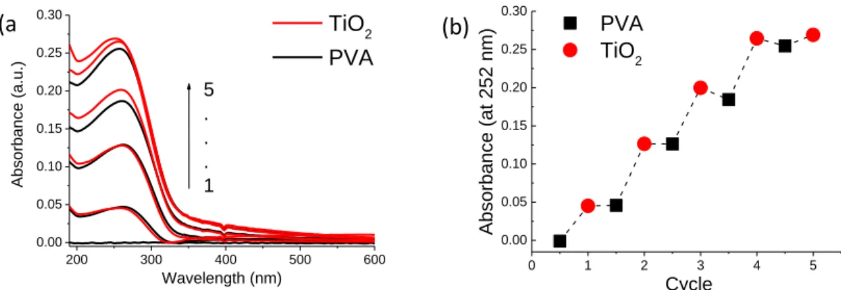
2.3.3 Film growth monitoring, morphological and mechanical properties
The nature of film growth was evaluated by measuring UV/Vis absorbance after each TiO2 coating.
Test sample was prepared directly on quartz glass along with the FS-NMs. UV/Vis spectra of 5 cycles of PVA/TiO2 deposition is shown in Figure 2-5a. The linear increase in absorbance of TiO2
at 252 nm against the cycles of deposition (Figure 2-5b) implied that TiO2 layer of similar thickness was deposited at each cycle. The UV-Vis observation is unable to track the deposition of PVA.
However, earlier works suggested that PVA is readily anchored to the titanium alkoxide due to abundancy of hydroxyl groups on its surface.14
200 300 400 500 600
0.00 0.05 0.10 0.15 0.20 0.25 0.30
Absorbance (a.u.)
Wavelength (nm)
TiO2 PVA 5
. . . 1
0 1 2 3 4 5
0.00 0.05 0.10 0.15 0.20 0.25
0.30 PVA
TiO2
Absorbance (at 252 nm)
Cycle
Figure 2-5. (a) UV/Vis absorption spectra of sequential PVA/TiO2 deposition, (b) UV/Vis absorbance at 252 nm of consecutive PVA and TiO2 layers.
(a )
(b)
Large-size self-supporting nanomembrane was obtained after dissolving the sacrificial layer in EtOH (Figure 2-6a). This step is also illustrated schematically in Figure 2-2. The nanomembrane suspended freely in the detaching solvent. The scanning electron microscope investigation showed that the fabricated nanomembrane has smooth and uniform surface (Figure 2-6b). Large defects or cracks were not seen under SEM, even after macroscopic manipulations. Figure 2-6d demonstrates the cross-sectional views of a 60 nm thick PVA/TiO2 FS-NM after being transferred onto a porous alumina support. The membrane consisted of 6.5 cycles (13 alternate layers of PVA and TiO2).
The membrane thickness was uniform throughout, and the average thickness for one cycle deposition of PVA and TiO2 is estimated to be about 10 nm. From this, the thickness of a single layer of PVA or TiO2 can roughly be estimated as ~ 5 nm. In fact, the hydrodynamic radius of PVA with 78900 g/mol (which is close to that of PVA used in the present experiment) in solution is about 15 nm.17 The corresponding radius of PVA chains in the solid film should be smaller than 15 nm. Thus, the PVA monolayer may not rough the surface of each PVA/TiO2 bilayer, resulting in smooth PVA/TiO2 multilayer membrane.
Although layered morphologies were vaguely seen in the membrane’s cross-sectional image (Figure 2-6c), no inter-space between layers was observed, suggesting that the layers were well adhered. The good interfacial fusion could be facilitated by the sol-gel reaction at the PVA-TiO2
interface. The ultrathin coating of membrane components (~ 5 nm) also plays an important role for the formation of well-integrated membrane structure.
Figure 2-6. LbL assembled (PVA/TiO2)6.5 composite nanomembranes. (a) Digital photograph of the detached large-size FS-NM (ca. 10 cm2) floating on EtOH solution. (b) Surface and (c) cross- sectional view SEM images of the FS-NMs transferred onto a porous alumina (Anodisc) support.
(d–f) Digital photographs showing the aspiration and release process of a centimeter-scale nanomembrane into a micropipette: (d) aspiration (e) assistance by a tweezer to stretch the folding (f) stretched nanomembrane. Scale bars: Digital images 1 cm, SEM images 500 nm.
The prepared nanomembrane was very flexible as demonstrated by the aspiration and release process of a centimeter-scale nanomembrane through a micropipette with a hole diameter of 2 mm (Figure 2-6d). The detached membrane, which was floating in EtOH, was aspirated into the micropipette and released back to the solvent. The membrane undergoes multiple bending to fit the mouth of the micropipette during the sacking/release process. Once released into the solvent, the film regained its original shape and size through a simple assistance by a laboratory tweezer (Figure 2-6e, f). The excellent flexibility could be explained by the molecular level fusion of the membrane components. The ultrathin PVA network surrounds the ultrathin amorphous rigid structure of TiO2 forming a multiple sandwich type structures, this in turn allows the movement TiO2 layer to bend along with PVA without breaking.
A PVA/TiO2 nanomembrane consisted of as low as 3 cycles (ca. 30 nm thick) could be detached, and successfully transferred onto a porous support without any significant damage. However, membranes under 50 nm thickness didn’t show reproducible gas permeation resistance. This should be attributed to the presence of pin-holes possibly formed during membrane manipulation (such as detachment, transferring onto porous support or during set up for permeance experiment).
2.3.4 Gas permeation property
Gas permeation of the (PVA/TiO2)6.5 nanomembrane was tested for two purposes; in order to evaluate the degree of defects in the membrane as well as to study the gas separation behavior of the membrane materials.
A N2/CO2 (95:5) mixture gas was used, and the permeance and CO2/N2 selectivity of ca. 60 nm thick nanomembrane was determined based on Equations 2-1 and 2-2. The results are presented in Figure 2-7. The membrane showed low gas permeance property, in part, demonstrating that the nanomembrane did not have serious defects or pin-holes that can lead to gas leakage. This is essential from FS-NM design perspective. However, the low permeance is not desirable from
separation viewpoint. The weak affinity of PVA and TiO2 towards CO2 could be a possible reason for the low permeance and CO2/N2 selectivity. But it is difficult at this point to illuminate the contribution of cracks for low separation performance of the PVA/TiO2 nanomembrane.
1 2 3
0 10 20 30 40 50 60
N2 CO2
Permeance (GPU)
Measurement (#) N2 CO2 N2 CO2
0.8 0.9 1.0 1.1 1.2 1.3
Selectivity, (CO 2/N 2)
Figure 2-7. Gas permeance property of the PVA/TiO2 multilayer nanomembrane.
2.4 Discussion
Figure 2-4 shows the schematic illustration of the prepared PVA/TiO2 multilayer nanomembrane.
Although the gas permeation property of the nanomembrane was not satisfactory (being several orders smaller compared to conventional gas separation polymer membranes), the membrane structure suggests useful features in nanomembrane development.
In simple metal oxide/polymer double layer nanomembranes,16 it was difficult to achieve structural integrity of the polymer and MOx layers that leads to breaking of the MOx layer. On the other hand, LBL assembly proves the way for molecular fusion of ultrathin layers of MOx and polymer. Such multiple molecular scale fusion introduces macroscopic flexibility and robustness to the composite nanomembrane. This could be because the continuous polymer networks in the alternate coatings protect the MOx layers from breaking.
(a )
2.5 Conclusion
Large size, ultrathin (~ 50 nm) and freestanding organic/inorganic composite nanomembrane was prepared by spin-assisted LbL assembly of TiO2 and PVA. The nanomembrane did not have serious defects, even after transfer onto a porous support, as confirmed by SEM observation and gas permeation test. It also demonstrated excellent flexibility during macroscopic manipulation without any film fragmentation.
References
(1) Koros, W. J. Macromol. Symp. 2002, 188 (1), 13-22.
(2) Byrd, H.; Holloway, C. E.; Pogue, J.; Kircus, S.; Advincula, R. C., Knoll, W.
Langmuir, 2000, 16 (26), 10322–10328.
(3) Vendamme, R.; Onoue, S.Y.; Nakao, A.; Kunitake, T. Nat. Mater. 2006, 5 (6), 494–501.
(4) Dong, G.; Li, H.; Chen, V. J. Mater. Chem. A 2013, 1 (15), 4610.
(5) Zhu, X.; Tian, C.; Do-Thanh, C.-L.; Dai, S. ChemSusChem 2017, 10 (17), 3304–3316.
(6) Rajan, G. S.; Sur, G. I. L. S.; Mark, J. E.; Schaefer, D. W.; Beaucage, G. J. Polym. Sci.
Part B Polym. Phys. 2003, 41, 1897–1901.
(7) Kim, W. gwi; Nair, S. Chem. Eng. Sci. 2013, 104, 908–924.
(8) Galizia, M.; Chi, W. S.; Smith, Z. P.; Merkel, T. C.; Baker, R. W.; Freeman, B. D.
Macromolecules 2017, 50 (2), 7809-7843.
(9) Richardson, J. J.; Bjornmalm, M.; Caruso, F. Science 2015, 348 (6233), 2491.
(10) Xu, Z. L.; Yu, L. Y.; Han, L. F. Front. Chem. Eng. China 2009, 3 (3), 318–329.
(11) Cho, J.; Char, K.; Hong, J. D.; Lee, K. B. Adv. Mater. 2001, 13 (14), 1076–1078.
(12) Schubert, U. Chemistry and Fundamentals of the Sol–Gel Process. In: Schubert, U.;
Hüsing, N. editors. Synthesis of Inorganic Materials; 3rd edn, VCH‐Wiley Verlag GmbH, Weinheim, Germany, 2012; pp. 1-28.
(13) Byrd, H.; Holloway, C. E.; Pogue, J.; Kircus, S.; Advincula, R. C.; Knoll, W. Langmuir 2000, 16 (26), 10322-10328.
(14) Hashizume, M.; Kunitake, T. Langmuir 2003, 19 (24), 10172–10178.
(15) Huang, G.; Mei, Y. Adv. Mater. 2012, 24 (19), 2517–2546.
(16) Mersha, A.; Selyanchyn, R.; Fujikawa, S. CleanE 2017, 1 (1), 80–89.
(17) Budhlall, B. M.; Landfester, K.; Sudol, E. D.; Dimonie, V. L.; Klein, A.; El-Aasser, M. S.
Macromolecules 2003, 36 (25), 9477–9484.
Chapter 3 Metal oxide/polymer blends for the preparation of free-standing nanomembranes and their gas permeation properties
Abstract
In this chapter, the development of free-standing nanomembrane (FS-NMs) from a blended type of organic/inorganic composites has been discussed. Blending approach can offer atomic scale in- situ interaction of organic and inorganic structures in a membrane. Here, a hydroxyl-terminated polyethylene glycol (PEG-OH) and silicon tetraisocyanate were premixed, and spin-coated to prepare FS-NMs. PEG-OH has been selected as a polymer precursor to take advantage of its compatibility with metal oxides for sol-gel reaction and its CO2 solubility-selectivity behavior.
Although no mechanical property enhancement was observed, compared to the PVA/TiO2 LBL nanomembrane discussed in Chapter 2, the PEG/SiO2 hybrid membrane demonstrated improved CO2/N2 selectivity.
3.1 Introduction
Polymeric films become weak upon thinning to a nanometer-scale and some polymers are difficult to spun into ultrathin films,1 making it unfavorable to prepare purely organic free-standing nanomembranes (FS-NMs). On the other hand, inorganic materials are rigid and difficult to handle as nanomembranes. Organic/inorganic composite materials combine these conflicting features of polymers and inorganics, and thus, enable the development of mechanically enhanced self- supporting nanomembranes.2
In addition to incorporation of inorganic fillers into a polymer matrix, composite membranes are prepared by molecular scale integrations such as layer by layer (LBL) assembly2,3 and simply blending the organic and inorganic components prior to membrane preparation.4 This molecular scale approaches enable atomic or molecular level interactions that are essential for the development of mechanically reinforced FS-NMs. Apart from mechanical reinforcement, composite membranes possess higher thermal stability,5 compared to the pristine polymer.
According to Kunitake’s group,4 organic/inorganic hybrid interpenetrating networks are interesting pathways to prepare FS-NMs of only a few tens nanometer thickness with large macroscopic size and flexibility. They fabricated nanomembranes from blend formula of the corresponding metal oxide and polymer precursors. But the membranes were not tested for applications such as separation. Similarly, tough hydrogel membranes with micrometer-scale thickness have been developed via non-covalent double network strategy by Gong’s6 and other groups7 for potential applications such as post-operative antiadhesive and biosensor membranes.
These mechanically robust materials are the motivations to the present work for preparing ultrathin separation membrane employing organic/inorganic hybrid materials. In this work, a metal oxide/polymer hybrid FS-NM was prepared by blending the components prior to membrane fabrication (Figure 3-1). Blending approach can offer atomic scale in-situ interaction of organic and inorganic structures in a membrane. As discussed in Chapter 2, I previously prepared free- standing and ultrathin PVA/TiO2 composite membrane via LBL assembly. Despite large lateral size and macroscopic flexibility of the nanomembranes, the CO2/N2 separation performance was not satisfactory. In addition to the weak CO2 affinity of PVA, the low separation performance (especially low selectivity) could be associated to pinholes formed either during membrane
preparation or processing steps. This, in turn, may come from the hard nature of the nanomembrane where PVA didn’t soften the oxide phase sufficiently.
Thus, in addition to changing the membrane architecture, a softer polymer with more CO2 affinity property was employed aiming to prepare mechanically stable, yet CO2 selective nanomembrane.
Figure 3-1: General representation of hybrid nanomembrane preparation process.
Hydroxyl-terminated polyethylene glycols (PEG-OH) are potential candidates due to their compatibility with metal oxides for sol-gel reactions (Figure 3-1), and their CO2 solubility selectivity behavior.8 Alkoxides are often used as metal oxide precursors. In this study, however, silicon tetraisocyanate was utilized as a source of SiO2 due to its good reactivity, compared to alkoxides. Like alkoxides, the sol-gel reaction involving Si(NCO)4 goes readily to completion as confirmed by previous study.9
Figure 3-2: Scheme for the formulation of organic/inorganic blend material.
In this chapter, the preparation of PEG-OH/SiO2 hybrid nanomembrane with preferential selectivity to CO2 over N2 has been presented. In order to completely avoid gas leakage, a caulking layer of polydimethylsiloxane (PDMS)10 was employed. To the best of my knowledge, gas permeation properties of such hybrid and free-standing ultrathin membranes have not been studied.
3.2 Experimental Section 3.2.1 Materials
Silicon wafer with 350 µm thickness and glass substrate were used to spin-coat nanomembranes.
Poly(4-vinylphenol) (PVP, Mw=11000, Sigma-Aldrich) was used as a sacrificial layer.
Polyethylene glycol (Mw=2000, Wako Ltd.) was employed as a polymer precursor. Silicon tetraisocyanate (SiNCO)4 (Matsumoto Fine Chemicals Co., Ltd.) and Titanium n-Butoxide (Ti(OnBu)4, Gelest Inc.) were used as metal oxide precursors. Polydimethylsiloxane (PDMS, Sylgard® 184) was used as caulking layer. Ethanol, chloroform and n-hexane were purchased from Wako Co., Ltd. and used as received. Deionized water (18.3 M cm−1, Millipore, Direct- QTM) was used for rinsing and solution preparation.
3.2.2 Nanomembrane preparation
In the preliminary step, separate solutions of Si(NCO)4 and PEG-OH were prepared in chloroform, and slowly mixed to prepare blend solutions of PEG-OH and Si(NCO)4 in varying ratios (Table 3- 1). In the meantime, a glass substrate was cleaned by sonication in EtOH for 60 min and subsequent rinsing by deionized water. The glass substrate was dried by air-blowing and treated with oxygen plasma for 4 min to hydrophilize its surface (the oxygen plasma treatment is described in Chapter 2). Afterwards, a PVP (15 wt%, in EtOH) sacrificial layer was spin-coated (3000 rpm, 60 sec) on the glass substrate and heated at 120 C for 5 min.
Table 3-1. PEG-OH and Si(NCO)4 ratio optimization from the view point of reactive sites and membrane formation tendency.
S/N 1 2 3 4 5 6
Molar ratio (PEG-OH/SiO2) 9:1 4:1 2:1 1:1 1:2 1:4 Concentration
(Total = 400 mM)
PEG-OH 360 320 268 200 132 80
SiO2 40 80 132 200 268 320
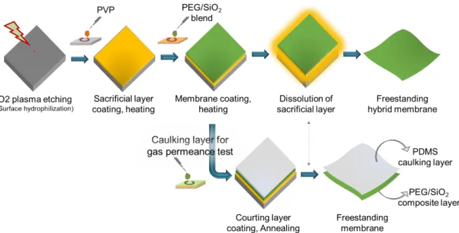
Once cooled down to room temperature, a PEG-OH/SiO2 blend solution was deposited on the pre- coated sacrificial layer at 3000 rpm for 2 min, and heated at 100 ºC for 12 hrs. For membranes to be used in gas permeation test, a 10 wt% PDMS caulking layer was spin-coated. Finally, the glass substrate was immersed in ethanol to dissolve the sacrificial layer and release the free-standing
nanomembrane. The overall membrane preparation process is illustrated schematically in Figure 3-3.
Figure 3-3. Schematic representation of nanomembrane fabrication process by spin-coating.
Film thickness and surface morphology were investigated by field emission scanning electron microscope (FE-SEM, Hitachi S-5200). Specimen for surface observation was prepared by transferring the nanomembrane onto supports such as anodized porous alumina (Anodisc, G.E.
Healthcare).
3.2.3 Gas permeation experiment
For gas permeation test, the prepared nanomembranes were transferred onto a porous polyimide support. After transfer onto a porous support, membrane area (space through which gas molecules pass) was limited by Kapton tape with the open hole of 1 cm diameter as illustrated in Figure 2- 3a, Chapter 2.
Subsequently, the membrane was placed in a home-made membrane cell, and gas permeation was measured using a bubble flow meter (Figure 3-4 below). The pure gas flow rate in cm3/min of CO2
and N2 was measured and converted into permeance (P) using the following equation. Selectivity () was also determined as the ratio of permeance.
𝑃 = 𝑁
𝐴 . 𝛥𝑃 (Eq. 3-1)
𝛼 = 𝑃𝐶𝑂2
𝑃𝑁2 (Eq. 3-2)
where N (m3/sec) refers to the flow rate measured on the permeate side, A (m2) is effective membrane area and P (Pa) is pressure difference between the feed and permeate side. In the experiment, effective area of gas permeation was 0.785 cm2. For convenience, permeance was reflected in the common GPU unit, where 1GPU = 7.510-12 m3/m2sPa, at standard temperature and pressure conditions.
Figure 3-4. Single gas permeation measurement apparatus. The flow rate of CO2 and N2 was measured separately and transformed into permeance. Helium was used as a sweep gas in both cases. The feed gas volume and pressure conditions were set at 100 sccm and 0.2 MPa, respectively.
3.3 Results and discussion
3.3.1 Membrane material selection and preparation conditions
In preparing a blend solution, suitable mixing ratio of the polymer and MOx precursor is very important for homogenous distribution of organic and inorganic structures. The PEG-OH/SiO2
ratio was determined based on the sol-gel reactive sites of the PEG-OH and MOx precursor; i.e., the number of OH-groups per mole of PEG-OH and the number of NCO-groups in Si(NCO)4. PEG-OH has two reactive sites and Si(NCO)4 has four reactive sites per mole. Thus, stoichiometrically, 2 moles of PEG-OH react with 1 mole of Si(NCO)4 (i.e., PEG-OH/Si(NCO)4
ratio of 2:1).
Based on this, wide range of ratios were prepared and evaluated for their film formation behavior.
The result is summarized in Table 3-2. Also, the effect of temperature on membrane formation and stability was studied. Films were annealed at 100 ºC to facilitate the sol-gel reaction.
Table 3-2. PEG-(OH)2/Si(NCO)4 ratio optimization from the viewpoint of membrane formation behavior.
Annealing condition
PEG-(OH)2/Si(NCO)4 ratio*
9:1 4:1 2:1 1:1 1:2 1:4
Ambient, 12hrs No film Film formed,
but fragile Solution was not stable for film preparation
(Fast hydrolysis) 100 ºC, 12 hrs Non-detachable film Stable free-standing
film
*Molar ratio; PEG-OH : Si(NCO)4
As can be seen in Figure 3-5 and Table 3-2, there was an obvious enhancement in the chemical and mechanical stabilities of the prepared nanomembranes after thermal treatment, compared to ambient condition. This should be because heating facilitated the sol-gel crosslinking reaction.
Accordingly, stable free-standing PEG-OH/SiO2 hybrid nanomembranes were obtained from thermally annealed 2-to-1 and 1-to-1 combination of PEG-OH/Si(NCO)4. The membranes maintained their shape and size after detachment from substrates.
Figure 3-5. Digital images showing the difference in the stability of the PEG-OH/Si(NCO)4 films during immersion in EtOH for detachment. (a) PEG-OH/Si(NCO)4 film directly immersed in EtOH. The murky appearance of the solution indicates the dissolution of membrane components.
(b) PEG-OH/Si(NCO)4 film immersed in EtOH after annealing at 100 ºC. Solution remained clear implying that no new species was introduced into the solvent, except the PVP sacrificial layer.
3.3.2 Morphological and mechanical properties
In addition to blending ratio and annealing temperature, it is worth explaining that the reactivity of the MOx precursor affects the membrane formation and subsequent mechanical properties. As discussed in Chapter 2, Ti(OnBu)4 was used as a MOx precursor to prepare PVA/TiO2 composite nanomembrane. However, when replacing PVA by polyethylene glycol (for its softer nature with CO2 affinity property) to make PEG/TiO2 nanomembranes, the membranes became more fragile, even under heating at 70 ºC for 12 hrs. The appearance of the nanomembranes is shown in Figure 3-6. Although the annealing temperature (70 ºC) was milder than the PEG-OH/SiO2 case (100 ºC), the main reason for film fragility could be attributed to lesser sol-gel reactivity of PEG-OH relative to PVA. Apparently, this could be due to lesser proportion of -OH groups in PEG-OH than PVA.
Therefore, Si(NCO)4 was tested instead of Ti(OnBu)4 as a MOx precursor to compensate the milder reactivity of PEG-OH.
Ambient 100 ⁰C, 12 h
(a) (b)
Figure 3-6. Nature of PEG-OH/TiO2 hybrid nanofilm under ambient condition (a) and annealing at 70 ºC for 12 hrs (b). Scale bar: 1 µm.
Interestingly, a better integrity with PEG-OH has been observed, leading to the realization of large size (Figure 3-7a), stable nanomembrane that can be detached and transferred onto a porous support without significant damage. As mentioned above, thermally annealed 2-to-1 and 1-to-1 molar ratios of PEG-OH/Si(NCO)4 form large size nanomembranes.
However, despite successful preparation of large size PEG-based nanomembrane, cracks were observed under SEM (Figure 3-7b,c). It was seen from physical manipulation and SEM observation that the PEG-OH/SiO2 nanomembrane has rigid nature. Although the mechanical property of this membrane was not satisfactory, I considered evaluating its gas separation property as a proof of design concept.
Figure 3-7. (a) Digital image of the PEG-OH/SiO2 nanomembrane while it was in the detachment solvent. (b,c) SEM image of the nanomembrane transferred onto a porous support. Scale bar: 10 µm.
3.3.3 Gas permeation property
Upon testing the gas permeation, the PEG-OH/SiO2 membrane showed frequent gas leakage problem. Sometimes, cracks were also observed in the nanomembranes by SEM (Figure 3-7c). On the other hand, although not reproducible, the membrane randomly showed CO2 selective separation behavior over N2. In situations like this, a caulking layer is applied to alleviate the effects of structural defects.10 Caulking materials need to have high gas diffusivities, so as not to hinder the performance of the separation layer. Accordingly, a PDMS caulking layer has been coated on PEG-OH/SiO2 (Figure 3-8) in order to seal the cracks and prevent simple gas leakage.
Figure 3-8. Schematics (left) and cross-sectional SEM view (right) of PEG-OH/SiO2
nanomembrane with PDMS caulking layer.
From the permeance and selectivity results in Table 3-3, the CO2/N2 selectivity of (PEG- OH/SiO2)/PDMS membrane was estimated as ca. 15. This value is higher than the CO2/N2
selectivity of pristine PDMS (11.6),11 signifying that the enhanced selectivity is due to PEG- OH/SiO2. This is reasonable as the ethylene oxide group in PEG-OH could assist the solubility- selectivity of CO2 over N2. However, the improved CO2/N2 selectivity was compromised by a decrease in permeance relative to pristine PDMS. This might be because the PEG-OH/SiO2 layer was very dense and had no molecular pathways. This, in turn, could be attributed to the presence of amorphous SiO2 in the membrane, as well as the crystalizing nature of PEG12 that restricts permeation pathways.
Table 3-3. Gas separation properties of pristine PDMS and PEG-OH/SiO2 with PDMS caulking layer.
Membrane
Permeance, GPU
CO2/N2
selectivity
CO2 N2
Pristine PDMS 3500.00 301.000 11.6
PEG-OH/SiO2
(with caulking layer) 5.50 0.370 14.8
PEG-OH/SiO2 layer
(Resistance model calculation) 5.52 0.371 14.9
The effect of the caulking layer on gas separation behavior of PEG-OH/SiO2 was examined by applying the resistance model.10,13,14 According to the model, the permeance of the double layer (PDL) membrane is related to the permeance of each layer as follows;
1
𝑃𝐷𝐿 = 1
𝑃𝑃𝐷𝑀𝑆 + 1
𝑃𝑃𝑆 (Eq. 3-3)
where, PPDMS and PPS are the permeances of PDMS caulking layer and PEG-OH/SiO2 selective layer, respectively.
This relation is valid only when the two layers are free of any defects. The PEG-OH/SiO2 layer, however, possessed cracks (Figure 3-7c), meaning that small part of the PDMS layer is not in contact with PEG-OH/SiO2. Therefore, the experimentally measured permeance (Pmeas) is not equal to PDL,14 but rather they are related as follows.
𝑃𝑚𝑒𝑎𝑠 = 𝑃𝐷𝐿 𝐴𝑃𝑆
𝐴𝑃𝐷𝑀𝑆 + 𝑃𝑃𝐷𝑀𝑆(1 − 𝐴𝑃𝑆
𝐴𝑃𝐷𝑀𝑆) (Eq. 3-4)
where, the APS/APDMS refers to the area of the PEG-OH/SiO2 layer covered by PDMS.
It is assumed (based on SEM observation) that the cracks in the PEG-OH/SiO2 layer constitute about 5% and the rest 95% of the membrane was covered by PDMS. The calculated permeance and selectivity values are listed in Table 3-3. However, there was no significant difference between the experimentally measured and model-based calculated values. This means that the caulking layer has almost no resistance on gas permeation, and the results reflect the behavior of PEG- OH/SiO2 layer. This, in turn, affirms that the PEG-OH/SiO2 nanolayer has no serious cracks.
3.4 Discussion
The idea of PEG-OH/TiO2 blend nanomembranes discussed in this chapter is a follow up of PVA/TiO2 LBL nanomembrane discussed in Chapter 1 with the aim to find out an alternative preparation route to integrate macroscopic mechanical property with CO2/N2 separation function.
Two possible ways were considered in order to overcome the low separation performance (where unsatisfactory mechanical stability could be a likely factor) of the PVA/TiO2 nanomembrane.
Using a softer polymer with better gas separation properties, and changing the membrane architecture. Accordingly, a blended type of PEG/TiO2 FS-NM was developed from a blend formula of a hydroxyl-terminated polyethylene glycol (PEG-OH) and silicon tetraisocyanate.
Although no observable mechanical property enhancement was seen, compared to the PVA/TiO2
membrane, the PEG/SiO2 hybrid nanomembrane demonstrated improved CO2/N2 selectivity.
The obtained results discussed in Chapter 2 and Chapter 3 implied that it is not smooth to improve mechanical property of a nanomembrane while maintaining the separation performance or vice versa only by changing membrane materials. In fact, it could be possible to tune both mechanical property and function of a nanomembrane together. However, this task would be time consuming and costly. Therefore, a more reliable membrane design that comprise fiber-reinforced polymer composites was considered as a preferable approach, and is discussed in Chapter 4.