Clarification of Cavitation Influence on Spray Atomization (2nd Report, Modeling of Cavitation inside Nozzle Based on Bubble Dynamics)
Masashi MATSUMOTO *1, Yoshimitsu KOBASHI *2, Eriko MATSUMURA *3, Jiro SENDA *4 (Received May 27, 2010)
In this research, it is purpose to understand the cavitation effects on fuel spray atomization. In this report, the numerical model predicted bubble behavior was proposed. The proposed numerical model treats that cavitation bubble grows or shrinks following to the pressure distribution inside nozzle hole. The calculation was carried out by use of estimated pressure distributions inside nozzle hole based on experimental measurements. Primary, for each injection pressure and test fuel, cavitation bubble behavior was calculated. Secondary, for various initial bubble radiuses, bubble growth and shrinkage processes were calculated. As results of these calculations, this model predicts the key points of bubble behavior adequately for various pressure history bubble undergoing and each initial bubble radiuses.
.
.H\ZRUGV㸸cavitation, atomization, spray, bubble dynamics, cavitation model
࣮࣮࢟࣡ࢻ㸸࢟ࣕࣅࢸ࣮ࢩࣙࣥ㸪ᚤ⢏㸪ᄇ㟝㸪ẼἻືຊᏛ㸪࢟ࣕࣅࢸ࣮ࢩࣙࣥࣔࢹࣝ
ᄇ㟝ᚤ⢏ᑐࡍࡿ࢟ࣕࣅࢸ࣮ࢩࣙࣥࡢᙳ㡪ࡢゎ᫂
( ➨ ሗ㸪ẼἻຊᏛ❧⬮ࡋࡓࣀࢬࣝෆ࢟ࣕࣅࢸ࣮ࢩࣙࣥࡢࣔࢹࣜࣥࢢ )
ᯇᮏ 㞞⮳*1㸪ᑠᶫ ዲ*2㸪ᯇᮧ ᜨ⌮Ꮚ*3㸪༓⏣ 㑻*4
ࡣࡌࡵ
ࡢ┠ぬࡲࡋ࠸ィ⟬ᶵჾࡢ⢭ᗘྥୖక࠸㸪◊
✲࣭㛤Ⓨศ㔝࠾ࡅࡿᩘ್ゎᯒࡢ㔜せᛶࡀ㧗ࡲࡗ࡚
࠸ ࡿ 㸬 ෆ ⇞ ᶵ 㛵 ศ 㔝 ࠾ ࠸ ࡚ ࡶ እ ࡛ ࡞ ࡃ 㸪 CFD(Computational Fluid Dynamics)ࡼࡿຠ⋡ⓗ࡞
ᶵ㛵タィࡸ⌧㇟ࡢヲ⣽ゎ᫂ᑐࡍࡿ㈉⊩ࡀᮇᚅࡉࢀ
࡚࠸ࡿ㸬
୍⯡ࡢᩘ್ゎᯒࢥ࣮ࢻࡣᗄከࡢࢧࣈࣔࢹࣝࡼࡾ
ᵓᡂࡉࢀ㸪ಶࠎࡢ≀⌮㐣⛬ᑐࡍࡿࣔࢹࣝᡭἲࡀ ゎᯒ⤖ᯝࡁ࡞ᙳ㡪ࢆཬࡰࡍ㸬≉㸪⇞ᩱᄇ㟝ࢆ
ᩘ್ⓗྲྀࡾᢅ࠺㝿ࡣ㸪⇞ᩱᄇᑕࡢึᮇ᮲௳࠾
ࡼࡧᾮศࣔࢹࣝࡀィ⟬⤖ᯝᑐࡋ࡚ᨭ㓄ⓗ࡞
ࡿࡓࡵ㸪ࡇࢀࡽ㛵ࡍࡿㅖ⌧㇟ࡢせⅬࢆⓗ☜ࡘ⡆
₩グ㏙ࡋᚓࡿᩘ್ࣔࢹࣝࡢᵓ⠏ࡀᮃࡲࢀࡿ㸬ᄇ㟝 ィ⟬࠾ࡅࡿᾮศ㐣⛬ࢆグ㏙ࡍࡿࣔࢹࣝࡋ࡚㸪 WAVEࣔࢹࣝ1)㸪TABࣔࢹࣝ2)ࡸKH-RTࣔࢹࣝ3)ࡀ ᖜᗈࡃ⏝ࡉࢀ࡚࠸ࡿ㸬ࡇࢀࡽࡢࣔࢹࣝඹ㏻ࡍࡿ
Ⅼࡋ࡚㸪ᄇᑕࡉࢀࡓᚋࡢ⇞ᩱᣲືࢆゎࡃࣔࢹ࡛ࣝ
࠶ࡿࡇ㸪ᐃᩘࡢኚ᭦ࡼࡿィ⟬⤖ᯝࡢᙳ㡪ࡀᴟ
ࡵ࡚ࡁ࠸ࡇࡀᣲࡆࡽࢀࡿ㸬୍᪉㸪㏆ᖺ࡛ࡣᄇ㟝
*1 Department of Mechanical and Engineering, Graduate School of Doshisha University, Kyoto Telephone:+ 81-774-65-7742, Fax:+81-774-65-7743, E-mail: [email protected]
*2 Department of Mechanical Engineering, Kanazawa Institute of Technology, Ishikawa
*3 Power Train Engineering Div.2 TOYOTA MOTOR CORPORATION, Shizuoka
*4 Department of Mechanical and Engineering, Doshisha University, Kyoto
ᚤ⢏ᑐࡋ࡚ࣀࢬࣝෆࡢὶືࡸࡑࡇ⏕ࡌࡿ࢟ࣕ
ࣅࢸ࣮ࢩࣙࣥ⌧㇟ࡢᙳ㡪ࢆ⪃៖ࡍࡁࡢᣦࡶከ ࡃ4-6)㸪ࡇࢀࡽࢆ⪃៖ࡋࡓᩘ್ࣔࢹࣝࡶࡲࡓᥦࡉࢀ
࡚࠸ࡿ7-9)㸬ࡋࡋ࡞ࡀࡽ㸪࠸ࡎࢀࡶࣀࢬࣝෆࡢ≧ἣ
ࢆึᮇ᮲௳ࡋ࡚⡆᫆ⓗ⪃៖ࡍࡿࡶࡢ࡛࠶ࡾ㸪ᐇ 㦂⤖ᯝẚ㍑᳨࣭ドࡍࡿ㝿ࡣᐃᩘኚ᭦ࡼࡿࣇ
ࢵࢸࣥࢢࡣචࢀ࡞࠸㸬ࡍ࡞ࢃࡕ㸪࠶ࡽࡺࡿ᮲௳
ᑐࡋ࡚ᐃᩘࡢኚ᭦࡞ࡋ⇞ᩱᄇ㟝ࢆண ࡋᚓࡿᩘ್
ࣔࢹࣝࡣᮍࡔᵓ⠏ࡉࢀ࡚࠸࡞࠸㸬ࡇࡢࡇࡣ㸪࢟ࣕ
ࣅࢸ࣮ࢩࣙࣥ⌧㇟ࡀᄇ㟝ᚤ⢏ཬࡰࡍᙳ㡪ࡀヲ⣽
ᢕᥱࡉࢀ࡚࠸࡞࠸ࡇ㉳ᅉࡍࡿ㸬
ࡑࡇ࡛㸪ᮏ◊✲࡛ࡣ⇞ᩱᄇ㟝ᑐࡍࡿ࢟ࣕࣅࢸ࣮
ࢩࣙࣥࡢᙳ㡪ࢆゎ᫂ࡍࡿࡇࢆ┠ⓗࡍࡿ㸬ᮏሗ࡛
ࡣ㸪➨1ሗ࠾࠸࡚ᐇ㦂ⓗᚓࡽࢀࡓᅽຊศᕸࢆࡶ
㸪Rayleigh-Plessetᘧࢆゎࡃࡇ࡛ẼἻᣲືࢆ⡆
᫆ⓗ⌧ࡍࡿࡇࢆヨࡳࡓ㸬ᐇ㦂⤖ᯝࡢẚ㍑࣭
᳨ドࢆ⾜࡞࠸㸪࢟ࣕࣅࢸ࣮ࢩࣙࣥ⌧㇟ࢆᩘ್ⓗྲྀ
ࡾᢅ࠺㝿⪃៖ࡍࡁⅬࡘ࠸᳨࡚ウࡋࡓ㸬
ィ⟬᪉ἲ ẼἻ༙ᚄᒚṔࡢ⟬ฟ
↓㝈ᾮయ୰࠾ࡅࡿ⌫ᙧẼἻࡢᡂ㛗࣭⦰㐣⛬ࡣ
ḟࡢRayleigh-Plessetࡢᘧࡼࡾ⟬ฟࡉࢀࡿ㸬
) 1 (
2 3 2
r w l
P P R
R
R
U
࣭࣭࣭(1)
(1)ᘧ࠾࠸࡚㸪R㸪Ul࠾ࡼࡧPrࡣࡑࢀࡒࢀẼἻ༙ᚄ㸪 ᾮయࡢᐦᗘ࠾ࡼࡧ↓㝈㐲ࡢὶయᅽຊ࡛࠶ࡿ㸬ࡲࡓ㸪
R࠾ࡼࡧRࡣ㛫ࢆtࡋࡓሙྜࡑࢀࡒࢀdR/dt㸪
2 2R/dt
d ࢆពࡍࡿ㸬୍᪉㸪PwࡣẼἻቨ࠾ࡅࡿὶ యᅽຊ࡛࠶ࡾ㸪(2)ᘧ࡛࠼ࡽࢀࡿ㸬
R R R
R R P R
P
P l l
n l
r v w
P V
V 2 4
2 0 3
0
0 ¸
¹
¨ ·
©
¸¸§
¹
¨¨ ·
©
§
࣭࣭࣭(2)
ࡇࡇ࡛㸪n ࡣ࣏ࣜࢺ࣮ࣟࣉᣦᩘ㸪Vlࡣᾮయࡢ⾲㠃ᙇ ຊ㸪Plࡣᾮయࡢ⢓ᗘ㸪Pvࡣὶయࡢ㣬Ẽᅽ㸪Pr0
ࡣึᮇࡢ࿘ᅖὶయᅽຊ㸪R0ࡣึᮇẼἻ༙ᚄ࡛࠶ࡿ㸬
ẼἻ⦰࣭ᔂቯ⏕ࡌࡿ࢚ࢿࣝࢠࡢ⟬ฟ ᔂቯ┤๓ẼἻࡀ⦰ࡍࡿ㏿ᗘࡣᴟࡵ࡚㧗ࡃ㸪ᮏ
ࣔࢹ࡛ࣝࡣࡇࡢ್ࢆホ౯ࡍࡿ㸬⦰㐣⛬࠾࠸࡚⏕
ᡂࡉࢀࡿ࢚ࢿࣝࢠࢆ(3)ᘧ࡛ᐃ⩏ࡍࡿ㸬
¦³
¦
j
i R r
R R r
l shrink
i
i
dr r v R
N
E 1
2 24 )
2 ( S
U ࣭࣭࣭(3)
(3)ᘧ࠾࠸࡚㸪i ࡣẼἻࡀ༙᭱ᚄ㐩ࡍࡿ㝿ࡢ
้㸪jࡣᔂቯࡍࡿ㝿ࡢ้ࢆ♧ࡍ㸬࡞࠾㸪N(R)ࡣ࢟ࣕ
ࣅࢸ࣮ࢩࣙࣥẼἻࡢᩘ࡛࠶ࡾ㸪ᮏሗ࡛ࡣ N(R)=1 ࡋࡓ㸬ࡲࡓ㸪⦰࠾ࡅࡿẼἻ㏿ᗘV࠾ࡼࡧ࿘ᅖ ὶయࡢ㏿ᗘvࡣࡑࢀࡒࢀࡢ⾲㠃✚㛵ࡋ㏫ẚࡢ㛵 ಀ࠶ࡿࡇࡽ㸪(4)ᘧࡀᑟࢀࡿ㸬
2 2 max
r R V
v
࣭࣭࣭(4) (4)ᘧ࠾ࡅࡿ Rmax㸪r ࡣࡑࢀࡒࢀ᭱ẼἻ༙ᚄ࠾ࡼ
ࡧྛ้ࡢẼἻ༙ᚄ࡛࠶ࡿ㸬(3)ᘧ(4)ᘧࢆ௦ධࡍࡿ
ࡇ࡛(5)ᘧࢆᚓࡿ㸬
¦³
¦
¸¸¹
·
¨¨
©
j §
i R r
R r
i R
l shrink
i
i
dr r r V
R R N E
1
2 2
2 2
4 )
2 ( S
U ࣭࣭(5)
ࡲࡓ㸪ᓥࡽ10)ࡼࢀࡤ㸪㠀ᅽ⦰ᛶὶయ࠾࠸࡚ẼἻ ࡀᔂቯࡍࡿ㝿⏕ࡌࡿ᭱⾪ᧁἼᅽຊ Pmaxࡣ (6)ᘧ
࡛⾲ࡉࢀࡿ㸬
brk l
brk R
R P R
P 0 3N 2V
0
max ¸¸
¹
¨¨ ·
©
§ ࣭࣭࣭(6)
ࡇࡇ࡛㸪P0ࡣึᮇࡢẼἻෆᅽຊ㸪Rbrkࡣᔂቯ࠾
ࡅࡿẼἻ༙ᚄ㸪Nࡣ᩿⇕ᣦᩘ࡛࠶ࡿ㸬ࡇࢁ࡛㸪(6) ᘧࡣึᮇẼἻ༙ᚄ࠾ࡼࡧᔂቯ࠾ࡅࡿẼἻ༙ᚄࡢ 㛵ಀࡼࡾᵓᡂࡉࢀࡿ㸬ࡋࡋ㸪(2)ᘧ࠾࠸࡚㣬
Ẽᅽ Pvࢆ⪃៖ࡋ࡚࠸ࡿࡇࡽࡶ᫂ࡽ࡞ࡼ࠺㸪 ᐇ㝿ࡣẼἻࡢᡂ㛗㐣⛬࠾࠸࡚⇞ᩱẼࡀẼἻෆ 㒊✚ࡉࢀࡿ㸬ࡇࡢࡇࢆ⪃៖ࡍࡿ㸪(6)ᘧࡼ
ࡿᅽຊ್ẚࡋ࡚ࡉࡽ㧗࠸⾪ᧁἼᅽຊࡀ⟬ฟࡉࢀ
ࡿࡓࡵ㸪ᮏሗ࡛ࡣ(6)ᘧࢆ(7)ᘧࡢࡼ࠺ኚᙧࡍࡿ㸬
brk l brk
R R R
P R
P max 3N 2V
max
max ¸¸¹
¨¨ ·
©
§ ࣭࣭࣭(7)
ࡇࡇ࡛㸪PRmaxࡣẼἻࡀ᭱ẼἻᚄ㐩ࡋࡓ㝿ࡢẼἻ ෆᅽຊ࡛࠶ࡾ㸪ᮏࣔࢹ࡛ࣝࡣ⇞ᩱࡢ㣬Ẽᅽࡋ ࡓ㸬࡞࠾㸪ᮏࣔࢹ࡛ࣝࡣẼἻᔂቯࢆ᩿⇕ኚ௬ ᐃࡋ㸪N=1.4 ࡋࡓ㸬ࡓࡔࡋ㸪ẼἻࡢ⦰㐣⛬㉳
ࡇࡿẼࡢจ⦰ࡣ↓どࡋࡓ㸬ࡇࢀࡣẼἻᔂቯࡢ᭱⤊
ẁ㝵࠾࠸࡚⦰㏿ᗘࡀᴟࡵ࡚㧗㏿࡞ࡿሙྜ㸪
Ẽࡢจ⦰ࡀẼἻ⦰㏣࠸ࡘ࡞࠸ሙྜࡶ࠶ࡿ⪃
࠼ࡓࡓࡵ࡛࠶ࡿ㸬ᔂቯࡢᅽຊࡀ࿘ᅖὶయࡢࢀࢆ
ㄏⓎࡍࡿ⪃࠼ࡓሙྜ࠾ࡅࡿ࢚ࢿࣝࢠࡣ(8)ᘧ࡛
⾲ࡉࢀࡿ㸬
¦
R
brk
collapse N R P R R
E ( ) max( ) 3
3
4S ࣭࣭࣭(8)
౪ヨᾮయ
ᮏィ⟬࡛ࡣ㸪➨1ሗ♧ࡋࡓᄇᏍ㒊ࡢᙳ⤖ᯝ
ẚ㍑ࡍࡿࡓࡵ㸪Table 1♧ࡍ3✀㢮ࡢ౪ヨᾮయࢆィ
⟬ᑐ㇟ࡋࡓ㸬
ẼἻ༙ᚄࡢィ⟬᪉ἲ
ᮏィ⟬ࡣ㸪➨1ሗ♧ࡋࡓ25ಸᣑࣀࢬࣝࢆ⏝
࠸ࡓᐇ㦂⤖ᯝࡼࡾ᥎ᐃࡋࡓᅽຊศᕸࢆ⏝࠸ࡿ㸬ᐇ㦂
⏝࠸ࡓ౪ヨࣀࢬࣝᙧ≧࠾ࡼࡧྛ㒊ᑍἲࢆ Fig.1㸪
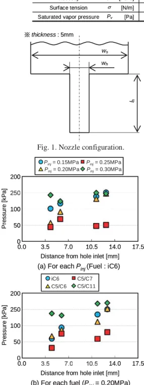
Table 2ࡑࢀࡒࢀ♧ࡍ㸬ࡲࡓ㸪ᐇ㦂⤖ᯝࡼࡾᚓࡽࢀ
ࡓᅽຊศᕸࢆ Fig.2 ♧ࡍ㸬ᐇ㦂ࡼࡾᚓࡽࢀࡓᅽຊ ศᕸࡢ᥎ᐃ᪉ἲ࡞㸪ヲ⣽㛵ࡋ࡚ࡣ➨1ሗࢆཧ↷
ࡉࢀࡓ࠸㸬ᮏሗ࡛ࡣᄇᏍධཱྀ㒊ࡢὶయᅽຊࢆᾮయࡢ 㣬Ẽᅽ㸪ฟཱྀࡢᅽຊࢆẼᅽ௬ᐃࡋ㸪ࡇࢀࡽ
Fig.2 ♧ࡋࡓ⤖ᯝࢆ⤌ࡳྜࢃࡏ࡚ከ㡯㏆ఝࡍ
ࡿࡇ࡛ᄇᏍ㒊ࡢᅽຊศᕸࢆ⟬ฟࡋࡓ㸬௨ୖࡢ⤖ᯝ
ࡼࡾ㸪ᮏィ⟬⏝࠸ࡿᅽຊᒚṔࢆ Fig.3 ♧ࡍ㸬࡞
࠾㸪Fig.2(a)ࡢPinj=0.30MPa࠾ࡼࡧFig.2(b)ࡢC5/C11 ࡢ᮲௳ࡣhydraulic flipࢆ࿊ࡍࡿࡓࡵ㸪ᮏሗࡢィ⟬
ᑐ㇟ࡼࡾ㝖እࡋࡓ㸬ィ⟬㝿ࡋ㸪ẼἻࡣ࣋ࣝࢾ࣮
ᘧࡼࡾᚓࡽࢀࡿᖹᆒὶ㏿Vave➼㏿࡛ᄇᏍෆࢆὶࢀ
ࡿ࠸࠺௬ᐃࡢࡶ㸪ྛࢱ࣒ࢫࢸࢵࣉࡢᅽຊࢆ
࠼ࡓ㸬ࡲࡓ㸪ẼἻࡣ㣬Ẽᅽ௨ୗ࡞ࡗࡓⅬ࡛
ᡂ㛗ࢆ㛤ጞࡍࡿࡋ࡚࠾ࡾ㸪ᮏሗ࡛ࡣ࡚ࡢ᮲௳
࠾࠸࡚ẼἻࡣᄇᏍධཱྀ㒊ࡼࡾᡂ㛗ࢆጞࡵࡿࡇ࡞
ࡿ㸬ィ⟬ࡣẼἻ༙ᚄࡀẼἻᔂቯࡢ༙ᚄ Rbrkࢆୗᅇ
ࡿࡲ࡛⾜࡞࠸㸪ᮏሗ࡛ࡣRbrk=0.5Pmࡋࡓ㸬
Table 1. Test fuel properties.
3.6㽢104 2.4㽢104
2.3㽢104 [Pa]
Saturated vapor pressure
n-C5H12/n-C7H16
n-C5H12/n-C6H14
2-Methylpentane
[N/m]
[Pa䞉s]
[kg/m3]
1.8㽢10-2 1.8㽢10-2
1.8㽢10-2 Surface tension
2.9㽢10-4 2.9㽢10-4
3.0㽢10-4 Viscosity
6.5㽢102 6.6㽢102
6.5㽢102 Density
6䠖4 - 2䠖8
Mixture ratio (mole fraction)
iC6 C5/C6 C5/C7
Fuel Component
Pv: at bubble point U
P V
Pv [Pa] 2.3㽢104 2.4㽢104 3.6㽢104
Saturated vapor pressure
n-C5H12/n-C7H16
n-C5H12/n-C6H14
2-Methylpentane
[N/m]
[Pa䞉s]
[kg/m3]
1.8㽢10-2 1.8㽢10-2
1.8㽢10-2 Surface tension
2.9㽢10-4 2.9㽢10-4
3.0㽢10-4 Viscosity
6.5㽢102 6.6㽢102
6.5㽢102 Density
6䠖4 - 2䠖8
Mixture ratio (mole fraction)
iC6 C5/C6 C5/C7
Fuel Component
Pv: at bubble point U
P V Pv
Table 2. Dimensions of actual and enlarged nozzle.
ws
wh
lh
[mm]
[mm]
[mm]
20.00 0.80
Sac width
3.75 0.15
Hole width
17.50 0.70
Hole length
25-times Actual nozzle
enlarged nozzle (Slit type)
ws
wh
lh
[mm]
[mm]
[mm]
20.00 0.80
Sac width
3.75 0.15
Hole width
17.50 0.70
Hole length
25-times Actual nozzle
enlarged nozzle (Slit type)
iC6 C5/C6
C5/C7 C5/C11
Distance from hole inlet [mm]
0.0 14.0 17.5
(b) For each fuel (Pinj= 0.20MPa)
Pinj= 0.15MPa Pinj= 0.20MPa
Pinj= 0.25MPa Pinj= 0.30MPa
(a) For each Pinj(Fuel : iC6)
Pressure [kPa]
Distance from hole inlet [mm]
0.0 50
0 100 200
3.5 7.0 10.5 14.0 17.5
Pressure [kPa]
50 0 100 250 200
iC6 C5/C6
C5/C7 C5/C11
Distance from hole inlet [mm]
0.0 14.0 17.5
(b) For each fuel (Pinj= 0.20MPa)
Pinj= 0.15MPa Pinj= 0.20MPa
Pinj= 0.25MPa Pinj= 0.30MPa Pinj= 0.15MPa
Pinj= 0.20MPa
Pinj= 0.25MPa Pinj= 0.30MPa
(a) For each Pinj(Fuel : iC6)
Pressure [kPa]
Distance from hole inlet [mm]
0.0 50
0 100 200
3.5 7.0 10.5 14.0 17.5
j j
0 0 0 0 0 0 0 0 0 0 0 0
3 5
3 5 7 07 0 10 510 5 14 014 0 1717
0 0 0 0 0
C5/C6
0 0
0 0 14 014 0 1717
Pressure [kPa]
50 0 100 250 200
Fig. 2. Pressure distribution inside nozzle.
ws
wh
lh
䈜thickness : 5mm
ws
wh
lh
䈜thickness : 5mm
Fig. 1. Nozzle configuration.
ィ⟬⤖ᯝ
ᅽຊᒚṔࡢᕪ␗ࡼࡿẼἻ༙ᚄࡢᙳ㡪
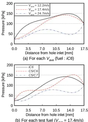
Fig.3 ♧ࡋࡓᅽຊศᕸࢆẼἻࡀ⤒㦂ࡍࡿᅽຊᒚ
Ṕࡋ㸪Rayleigh-Plessetᘧࢆ⏝࠸ࡓẼἻᚄィ⟬ࢆ⾜
࡞ࡗࡓ㸬ึᮇẼἻ༙ᚄR0ࢆ10Pmࡋࡓ㝿ࡢẼἻ༙
ᚄࡢᒚṔࢆᅽຊᒚṔࡶFig.4♧ࡍ㸬Fig.4ࡼ
ࡾ㸪ẼἻࡢ⤒㦂ࡍࡿᅽຊᒚṔࡀపᅽ࡛࠶ࡿ㸪᭱
ẼἻ༙ᚄࡣࡁࡃ࡞ࡾ㸪ࡑࡢᔂቯ⨨ࡣᄇᏍ㒊ࡢ
ୗὶ᪉ྥ᥎⛣ࡍࡿࡇࡀࢃࡿ㸬ࡲࡓ㸪ẼἻࡢ ᡂ㛗㏿ᗘẚࡋ࡚⦰ࡍࡿ㝿ࡢẼἻቨ㏿ᗘࡣ㠀ᖖ
㧗࠸ࡇࡸ㸪࿘ᅖὶయࡢᅽຊࡀ㣬Ẽᅽࢆୖᅇࡗ ࡓᚋࡶẼἻࡣ័ᛶຊࡢᙳ㡪ࡼࡾ࠶ࡿᮇ㛫ࡣᡂ㛗ࢆ
⥆ࡅࡿ࡞㸪ẼἻ༙ᚄࡢኚ㛵ࡍࡿᐃᛶⓗ࡞≉ᚩ ࡀᚓࡽࢀࡿࡇࡀ☜ㄆࡉࢀࡿ㸬ࡇࡇ࡛㸪ẼἻᔂቯ
⨨ࡢẚ㍑ᑐ㇟ࡋ࡚㸪Fig.5♧ࡍᐇ㦂ࡼࡾᚓࡽࢀࡓ
ᙳ⏬ീࢆ⏝࠸ࡿ㸬࡞࠾㸪⫼ᬒගᙳࡼࡾᚓࡽࢀ
ࡓ⏬ീ࡛࠶ࡿࡓࡵ㸪㯮ࡃᙳࡉࢀࡓ㡿ᇦࡀẼἻ㡿ᇦ
3.0 2.0
1.0
0.5 1.5 2.5
0.0 100
80 60 40 20 0 10-2 10-3 10-4 10-5 10-6
Pressure [kPa]Bubble radius [m] Vave= 12.2m/s Vave= 17.4m/s
= 24.7m/s
Distance from nozzle hole inlet [mm]
(a) For each Vave(fuel : iC6)
iC6
8.0 4.0
2.0 6.0 10.0
0.0 150 120 90 60 30 0 10-2 10-3 10-4 10-5 10-6
Pressure [kPa]Bubble radius [m]
Distance from nozzle hole inlet [mm]
(b) For each test fuel (Vave= 17.4m/s)
-2 -3 -4 -5 -6
0
-2 -3 -4 -5 -6
Vave
V
V = 12.2m/s Vave V
V = 17.4m/s
= 24.7m/s
0 iC6 0 0 0 0 0 0 0
0 0 0 0 0 0
3.0 2.0
1.0
0.5 1.5 2.5
0.0 100
80 60 40 20 0 10-2 10-3 10-4 10-5 10-6
Pressure [kPa]Bubble radius [m] Vave= 12.2m/s Vave= 17.4m/s Vave= 24.7m/s
Distance from nozzle hole inlet [mm]
(a) For each Vave(fuel : iC6)
iC6 C5/C6 C5/C7
8.0 4.0
2.0 6.0 10.0
0.0 150 120 90 60 30 0 10-2 10-3 10-4 10-5 10-6
Pressure [kPa]Bubble radius [m]
Distance from nozzle hole inlet [mm]
(b) For each test fuel (Vave= 17.4m/s) Fig. 4. Histories of bubble radius and pressure (initial bubble radius R0=10Pm).
0.0 3.5 7.0 10.5 14.0 17.5
Distance from nozzle hole inlet [mm]
Fuel [MPa]
[m/s]
0.15 12.2 iC6
0.20 17.4 iC6
0.25 21.3 iC6 Pinj
Vave
0.20 17.4 C5/C6
0.20 17.4 C5/C7
0.0 3.5 7.0 10.5 14.0 17.5
Distance from nozzle hole inlet [mm]
Fuel [MPa]
[m/s]
0.15 12.2 iC6
0.20 17.4 iC6
0.25 21.3 iC6 Pinj
Vave
0.20 17.4 C5/C6
0.20 17.4 C5/C7
Fig. 5. Cavitation image inside nozzle hole for each condition.
Vave= 12.2m/s Vave= 17.4m/s Vave= 24.7m/s 200
150 100 50 0
0.0 3.5 7.0 10.5 14.0 17.5
Pressure [kPa]
Distance from hole inlet [mm]
(a) For each Vave(fuel : iC6)
iC6 C5/C6 C5/C7 200
150 100 50 0
0.0 3.5 7.0 10.5 14.0 17.5
Pressure [kPa]
Distance from hole inlet [mm]
(b) For each test fuel (Vave= 17.4m/s)
iC6 C5/C6 C5/C7 0
0 0 0 0
Vave V
V = 12.2m/s Vave
V
V = 17.4m/s Vave
V
V = 24.7m/s 0
0 0 0 0
Vave= 12.2m/s Vave= 17.4m/s Vave= 24.7m/s 200
150 100 50 0
0.0 3.5 7.0 10.5 14.0 17.5
Pressure [kPa]
Distance from hole inlet [mm]
(a) For each Vave(fuel : iC6)
iC6 C5/C6 C5/C7 200
150 100 50 0
0.0 3.5 7.0 10.5 14.0 17.5
Pressure [kPa]
Distance from hole inlet [mm]
(b) For each test fuel (Vave= 17.4m/s) Fig. 3. Pressure distribution used for calculation.
࡛࠶ࡿ㸬⏬ീࡼࡾ᫂☜࡞ᔂቯ⨨ࡣᢕᥱ࡛ࡁ࡞࠸ࡀ㸪
࠾࠾ࡼࡑࡢ⨨ࡣ᥎ᐃྍ⬟࡛࠶ࡿุ᩿ࡋ㸪ᮏࣔࢹ
ࣝࡢẚ㍑ᑐ㇟ࡋ࡚⏝࠸ࡓ㸬Fig.4㸪5 ࡼࡾ㸪࠸ࡎࢀ
ࡢᅽຊᒚṔᑐࡋ࡚ࡶ㸪ẼἻィ⟬ࡼࡾᚓࡽࢀࡓᔂቯ
⨨ࡣ᫂ࡽᐇ㦂⤖ᯝࡼࡾࡶᄇᏍ㒊ࡢୖὶഃ
⨨ࡋ࡚࠸ࡿࡇࡀࢃࡿ㸬௨ୖࡢ⤖ᯝࡼࡾ㸪ẼἻࡢ ᔂቯ⨨ࡇࡑࡁࡃ␗࡞ࡿࡶࡢࡢ㸪ᮏࣔࢹ࡛ࣝࡣẼ Ἳࡢᅽຊሙᑐࡍࡿᐃᛶⓗ࡞ᣲືࢆ⾲⌧ࡍࡿࡇࡀ
ྍ⬟࡛࠶ࡿ࠸࠼ࡿ㸬
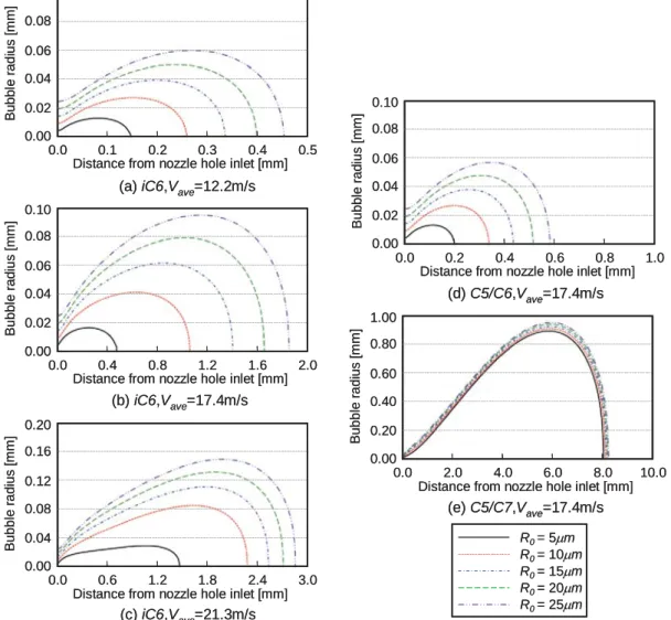
ึᮇẼἻ༙ᚄࡀẼἻᣲືཬࡰࡍᙳ㡪
ึᮇẼἻ༙ᚄ R0ࢆኚࡉࡏࡿࡇࡼࡾẼἻᣲ
ື࣭ᔂቯ⨨ࡀዴఱ᥎⛣ࡍࡿࢆ᳨ドࡍࡿ㸬Fig.3 ࡢᅽຊᒚṔᑐࡋ㸪ึᮇẼἻ༙ᚄR0ࢆ 5㹼25Pm ኚࡉࡏࡓሙྜࡢẼἻ༙ᚄᒚṔࢆFig.6♧ࡍ㸬Fig.6
ࡼࡾ㸪C5/C7 ΰྜ⇞ᩱࡢ᮲௳ࢆ㝖ࡃ࠸ࡎࢀࡢᅽຊᒚ
Ṕᑐࡋ࡚ࡶ㸪ึᮇẼἻ༙ᚄR0ࢆቑຍࡉࡏࡿࡇ
ࡼࡾ฿㐩ࡍࡿ᭱ẼἻ༙ᚄࡣࡁࡃ࡞ࡿࡇࡀࢃ
ࡾ㸪ึᮇẼἻ༙ᚄࡼࡿẼἻᣲືࡢᙳ㡪ࢆᐃᛶⓗ
ᤊ࠼࡚࠸ࡿ࠸࠼ࡿ㸬ࡋࡋ࡞ࡀࡽ㸪R0ࡢቑຍ
క࠸ẼἻᔂቯ⨨ࡣୗὶ᪉ྥ⛣ືࡍࡿࡶࡢࡢ㸪 ᐇ㦂⤖ᯝࡢᔂቯ⨨ࡣ฿㐩ࡋ࡞࠸ࡇࡀ☜ㄆࡉࢀ
ࡿ㸬୍᪉㸪C5/C7ΰྜ⇞ᩱࡢᅽຊᒚṔᑐࡋ࡚ᚓࡽ
ࢀࡓึᮇẼἻ༙ᚄ R0ࡢᙳ㡪ࡣࡢ᮲௳␗࡞ࡗ࡚
࠸ࡿ㸬ࡍ࡞ࢃࡕ㸪R0ࢆ5㹼25Pmࡢ⠊ᅖ࡛ኚࡉࡏ࡚
ࡶ᭱ẼἻ༙ᚄ࣭ᔂቯ⨨࠾࠸࡚ᕪ␗ࡀぢࡽࢀ࡞
࠸㸬ࡇࢀࡣ㸪ẼἻࡢᡂ㛗㏿ᗘࡀ࡞ࡿ㸪ึᮇẼ Ἳ༙ᚄࡀᚋࡢẼἻᣲືཬࡰࡍᙳ㡪ࡣᑠࡉࡃ࡞ࡿࡇ
ࢆ♧ࡋ࡚࠸ࡿ㸬࠸ࡎࢀࡋ࡚ࡶ㸪ึᮇẼἻ༙ᚄࢆ
ኚࡉࡏࡿࡢࡳ࡛ࡣᐇ㦂⤖ᯝࡢᔂቯ⨨ࢆ⌧ࡋᚓ
࡞࠸ࡇࡀ♧ࡉࢀࡓ㸬
0.0 0.1 0.2 0.3 0.4 0.5
0.10 0.08 0.06 0.04 0.02 0.00
Distance from nozzle hole inlet [mm]
Bubble radius [mm]
0.0 0.4 0.8 1.2 1.6 2.0
0.10 0.08 0.06 0.04 0.02 0.00
Distance from nozzle hole inlet [mm]
Bubble radius [mm]
0.0 0.6 1.2 1.8 2.4 3.0
0.20 0.16 0.12 0.08 0.04 0.00
Distance from nozzle hole inlet [mm]
Bubble radius [mm]
0.0 0.2 0.4 0.6 0.8 1.0
0.10 0.08 0.06 0.04 0.02 0.00
Distance from nozzle hole inlet [mm]
Bubble radius [mm]
0.0 2.0 4.0 6.0 8.0 10.0
1.00 0.80 0.60 0.40 0.20 0.00
Distance from nozzle hole inlet [mm]
Bubble radius [mm]
(a) iC6,Vave=12.2m/s
(b) iC6,Vave=17.4m/s
(c) iC6,Vave=21.3m/s
(d) C5/C6,Vave=17.4m/s
(e) C5/C7,Vave=17.4m/s R0 = 5Pm R0 = 10Pm R0 = 15Pm R0 = 20Pm R0 = 25Pm
0 0 2 0 4 0 6 0 8 0 10 0
0 0 0 0 0 0
0 0 0 2 0 4 0 6 0 8 1 0
0 8 6 4 2 0
0 0 0 6 1 2 1 8 2 4 3 0
0 6 2 8 4 0
0 0 0 4 0 8 1 2 1 6 2 0
0 8 6 4 2 0
0 0 0 1 0 2 0 3 0 4 0 5
0 8 6 4 2 0
0.0 0.1 0.2 0.3 0.4 0.5
0.10 0.08 0.06 0.04 0.02 0.00
Distance from nozzle hole inlet [mm]
Bubble radius [mm]
0.0 0.4 0.8 1.2 1.6 2.0
0.10 0.08 0.06 0.04 0.02 0.00
Distance from nozzle hole inlet [mm]
Bubble radius [mm]
0.0 0.6 1.2 1.8 2.4 3.0
0.20 0.16 0.12 0.08 0.04 0.00
Distance from nozzle hole inlet [mm]
Bubble radius [mm]
0.0 0.2 0.4 0.6 0.8 1.0
0.10 0.08 0.06 0.04 0.02 0.00
Distance from nozzle hole inlet [mm]
Bubble radius [mm]
0.0 2.0 4.0 6.0 8.0 10.0
1.00 0.80 0.60 0.40 0.20 0.00
Distance from nozzle hole inlet [mm]
Bubble radius [mm]
(a) iC6,Vave=12.2m/s
(b) iC6,Vave=17.4m/s
(c) iC6,Vave=21.3m/s
(d) C5/C6,Vave=17.4m/s
(e) C5/C7,Vave=17.4m/s R0 = 5Pm R0 = 10Pm R0 = 15Pm R0 = 20Pm R0 = 25Pm
Fig. 6. Effect of initial bubble radius on growth and shrinkage processes of cavitation bubbles.
ᚋࡢ᳨ウ㡯
๓⠇ࡲ࡛ᚓࡽࢀࡓ⤖ᯝࢆ⥲ྜࡍࡿ㸪ᮏࣔࢹࣝ
ࢆ⏝࠸ࡓィ⟬⤖ᯝࡣẼἻࡢ⤒㦂ࡍࡿᅽຊᒚṔࡁ ࡃᕥྑࡉࢀࡿ࠸࠼ࡿ㸬ࡑࡇ࡛㸪ᮏィ⟬⏝࠸ࡓᅽ ຊᒚṔࡘ࠸᳨࡚ウࡍࡿ㸬ୖ㏙ࡢ㏻ࡾ㸪ᮏሗ࡛ࡣᐇ 㦂ࡼࡾᚓࡽࢀࡓᅽຊศᕸࢆẼἻࡢ⤒㦂ࡍࡿᅽຊᒚṔ
ࡋ࡚ィ⟬ࢆ⾜࡞ࡗࡓ㸬ࡋࡋ࡞ࡀࡽ㸪ẼἻࡀᚠ⎔
ὶࢀᅾࡋ࡞࠸௬ᐃࡍࡿ㸪ᐇ㝿ࡣὶἢ ࡗ࡚ᄇᏍୗὶ㒊⛣ືࡍࡿ⪃࠼ࡽࢀࡿ㸬ࡇࢀࡼ
ࡾ㸪ὶ㒊࡚ẼἻࡢ⤒㦂ࡍࡿᅽຊᒚṔࡣᮏィ⟬
⏝࠸ࡓࡑࢀ␗࡞ࡿࡓࡵ㸪ィ⟬⤖ᯝᐇ㦂⤖ᯝࡢ
୍⮴ࡀ⏕ࡌࡓྍ⬟ᛶࡀ࠶ࡿ᥎ᐹࡉࢀࡿ㸬ࡲࡓ㸪
ᅇࡣ༢୍ẼἻࡘ࠸࡚ィ⟬ࢆ⾜࡞ࡗࡓࡀ㸪ᐇ㝿ࡣ ከᩘࡢẼἻࡀྠከⓎⓗⓎἻ࣭ᡂ㛗࠾ࡼࡧ⦰㐣
⛬ࢆ♧ࡍ⪃࠼ࡽࢀࡿ㸬ࡇࡢࡇࡽ㸪ከᩘࡢẼἻ ᣲືࡀ࠸ᙳ㡪ࢆཬࡰࡍྍ⬟ᛶࡀ㧗࠸࠸࠼ࡿ㸬 ࡍ࡞ࢃࡕ㸪ⓎἻẼἻᩘࡢቑຍక࠺ᄇᏍෆ࡛ࡢᅽຊ ኚືࡢ⦆11)ࡸ⾲㠃⢓ᛶࡢᙳ㡪12)࡞㸪ࡢᅉᏊ
ࡘ࠸࡚ࡶ᳨ウࡍࡿᚲせࡀ࠶ࡿ㸬ᚋࡣࡇࢀࡽࡢࡇ
ࢆ㋃ࡲ࠼㸪ᐇ㦂⤖ᯝࡢẚ㍑᳨࣭ドࢆ㔜ࡡࡿࡇ࡛
ண ⢭ᗘࡢྥୖࢆᅗࡿ㸬
⤖ゝ
ᮏ◊✲࡛ࡣከᵝ࡞ᄇᑕ᮲௳ᑐࡍࡿᄇ㟝≉ᛶࢆண ࡍࡿࡓࡵ㸪࢟ࣕࣅࢸ࣮ࢩࣙࣥ⌧㇟ࢆ⪃៖ධࢀࡓ ィ⟬ᡭἲࡢᵓ⠏ࢆ┠ⓗࡍࡿ㸬ᮏሗ࡛ࡣ㸪࢟ࣕࣅࢸ
࣮ࢩࣙࣥࣔࢹࣝࡘ࠸࡚ᴫㄝࡋ㸪ᐇ㦂ⓗᚓࡽࢀࡓ ᅽຊᒚṔࢆࡶ㸪ẼἻᣲືࢆ⡆᫆ⓗ⌧ࡍࡿࡇ
ࢆヨࡳࡓ㸬௨ୗᚓࡽࢀࡓ▱ぢࢆ♧ࡍ㸬
(1) ᮏࣔࢹࣝࡣẼἻ༙ᚄࡢኚ㛵ࡍࡿᐃᛶⓗ࡞≉
ᚩࢆグ㏙ࡍࡿ㸬
(2) ẼἻࡢᡂ㛗㏿ᗘࡀࡁࡃ࡞ࡿ㸪ึᮇẼἻ༙
ᚄࡀẼἻࡢᡂ㛗࣭⦰㐣⛬࠾ࡼࡧᔂቯ⨨ཬ
ࡰࡍᙳ㡪ࡣᑠࡉࡃ࡞ࡿ㸬
(3) ᐇ㦂⤖ᯝࢆ㐺ษ⌧ࡍࡿࡓࡵ㸪ẼἻࡢ⤒㦂ࡍ
ࡿᅽຊᒚṔࡢぢ┤ࡋࡸẼἻྠኈࡢ┦ᖸ΅ࢆ⪃
៖ࡍࡿ࡞㸪ᮏࣔࢹࣝࡣᚋࡢᨵၿࢆせࡍࡿ㸬
ཧ⪃ᩥ⊩
1) Pope, S. B., Computationally Efficient Implementation of
Combustion Chemistry using in Situ Adaptive Tabulation, Combustion and Theory Modeling, Vol.1, pp.41-63, (1997).
2) O’Rouke, P. J. and Amsden, A. A., The Tab Method for Numerical Calculation of Spray Droplet Breakup, SAE paper, No.872089, (1987).
3) Patterson, M. A., Reitz, R. D., Modeling the Effects of Fuel Spray Characteristics on Diesel Engine Combustion and Emission, SAE paper, No.980131, (1998).
4) ⋢ᮌఙⱱ, す⏣ᜨဢ, ΎỈṇ๎, ᘅᏳ༤அ, ࣀࢬࣝෆ ᄇᏍෆࡢ࢟ࣕࣅࢸ࣮ࢩࣙࣥࡀᾮయᄇὶࡢᚤ⢏ཬ
ࡰ ࡍ ᙳ 㡪, ᪥ ᮏ ᶵ Ე Ꮫ ㄽ ᩥ 㞟 B ⦅, 63(614), pp.3447-3454, (1997).
5) 㯮ṇᩄ, ྂ㤋ோ, ✄ᮧ㝯ኵ, ࣀࢬࣝෆ࢟ࣕࣅࢸ࣮ࢩ
ࣙࣥࡀᾮయศᶵᵓཬࡰࡍᙳ㡪(➨3ሗ㸪2Dࣀࢬࣝ
ෆࡢᅽຊኚື), ᪥ᮏᶵᲔᏛㄽᩥ㞟 B ⦅, 71(703), pp.811-816, (2005).
6) ᑠ➟ཎៅ, 㯮ṇᩄ, ࣀࢬࣝෆᾮయࡢࢀࡀᄇὶཬ
ࡰࡍᙳ㡪, ᪥ᮏᶵᲔᏛᮾᨭ㒊⛅Ꮨㅮ₇ㅮ₇ㄽ
ᩥ㞟, 20060930, pp.71-72, (2006).
7) Arcoumanis, C., Gavaises, M., Linking the Nozzle Flow with Spray Characteristics in a Diesel Fuel Injection System, Atomization and Sprays, Vol.8, pp.179-197, (1998).
8) Nishimura, A. and Assanis, D. N., A Model for Primary Diesel Atomization Based on Cavitation Bubble Collapse Energy, Proc. ICLASS-2000, pp.1249-1256, (2000).
9) Baumgarten, C., Shi, Y., Bush, R. and Merker, G. P., Numerical and Experimental Investigations of Cavitation Flow in High Pressure Diesel Nozzles, ILASS-Europe, (2001).
10) ᓥ❶, ⸨ཎᚨ୍, ᅽ⦰ᛶἜᅽసືἜ୰ࡢẼἻࡢᔂቯ, ᮾᏛ㧗㏿ຊᏛ◊✲ᡤሗ࿌, 46(407), pp.129-144, (1981).
11) ➉୰ ኵ, ᾆ ⏣ⱥ୕, ἜຊᏛ, 㣴㈼ᇽ, pp.206-223, (1968).
12) Ἳࡢ࢚ࣥࢪࢽࣜࣥࢢ, ࢸࢡࣀࢩࢫࢸ࣒, pp.19-29, (2005).