Environmental Applications of Repetitive Pulsed Power
journal or
publication title
IEEE Transactions on Dielectrics and Electrical Insulation
volume 14
number 4
page range 825‑833
year 2007‑08
URL http://hdl.handle.net/2298/9550
doi: 10.1109/TDEI.2007.4286513
1070-9878/07/$25.00 © 2007 IEEE
Invited Paper
Environmental Applications of Repetitive Pulsed Power
Hidenori Akiyama, Shunsuke Sakai, Takashi Sakugawa and Takao Namihira
Graduate School of Science and Technology, Kumamoto University 2-39-1 Kurokami, Kumamoto 860-8555, Japan
ABSTRACT
High repetition rate, high reliability and long lifetime are required for pulsed power generators for environmental applications. Also, it is necessary to optimize the pulsed power generator for each environmental application. Recent developments in pulsed power generators are described. In addition, recent research of gaseous phase pollution control using pulsed power, cleaning of lake and dam of algae bloom by discharges, and recycling of concrete by pulsed power is summarized.
Index Terms - Environmental application, pulsed power, discharge plasma, magnetic pulse compressor, streamer discharge, NOx removal, algae treatment, concrete recycling.
1 INTRODUCTION
SINGLE shot based pulsed power generators with extremely high peak power have been developed for military and nuclear fusion applications. The size and weight of these pulsed power generators become larger and larger because of the increase in primary stored energy. Successful development of these large pulsed power generators has produced new approaches in military and nuclear fusion research, for example electromagnetic launchers and inertial confinement nuclear fusion using X-ray radiation from Z- pinched plasmas produced by pulsed power.
On the other hand, repetitively operated pulsed power generators with a moderate peak power have been developed mainly for industrial applications [1-8]. The primary stored energy is small in comparison with single shot based pulsed power generators. Not only are the reliability and quality of the pulsed power outputs are important, but also the lifetimes of the pulsed power generators are very important to achieve industrial applications with pulsed power.
Development of pulsed power generators optimized for industrial applications have stimulated research of many kinds of applications.
Here, recent research for environmental applications of pulsed power is summarized. Initially, developments of repetitive pulsed power generators for industrial applications are described, and then gaseous phase pollution control using pulsed power, cleaning of lake and dam algae bloom by discharges in the water and recycling of concrete by pulsed power are described.
2 REPETITIVE PULSED POWER GENERATORS
Development of power semiconductor devices has improved the performance of fast and high-power switching devices. Progress of developing all solid-state pulsed power generators is reviewed with particular emphasis on environmental applications.
In recent years, research on and development of practical industrial applications of repetitive pulsed power has been done using a semiconductor switch and a magnetic switch.
The research has focused on microlithography light sources for a long time. In particular, an excimer laser and a high energy density plasma (extreme ultraviolet source), which are used in semiconductor fabrication, require a high repetition rate, high reliability and long lifetime. Therefore, most of the light sources for microlithography use all solid-state pulsed power generators with semiconductor switches and magnetic switches as their driver [1-3].
Moreover, the applications of pulsed power discharges to environmental fields have been studied. Some of the examples are decomposition of harmful gases, generation of ozone, treatment of algae bloom by discharge plasmas in water, and concrete recycling [4-7]. In these applications, repetitive operation and long lifetime are also necessary in the pulsed power generators. Here, all solid-state repetitive pulsed power systems for environmental applications are described.
2.1 MAGNETIC PULSE COMPRESSOR FOR EXHAUST GAS TRATMENT AND OZONIZER An ozonizer with short pulse electric discharges allows the use of a simpler discharge tube than in the silent discharge
Manuscript received on 24 January 2007, in final form 26 February 2007.
electrodes. The ozonizer discharge tubes consist of a cylindrical ground electrode and a high voltage center electrode in the form of a straight or spiral wire. A pulsed power generator with a very short high voltage pulse is necessary to produce pulsed streamer discharges along the long center electrode. The circuit of the magnetic pulse compressor (MPC) for the pulse ozonizer is shown in Figure 1. The command charger (H.V. Charger) is used to charge the capacitor, C0. After the gate-turn-off thyristor (GTO) is turned on, current I0 flows. The saturable inductor (SI0) is then turned on after the magnetic assist time elapses.
Stepping up the voltage with the pulse transformer (PT) and saturable transformer (ST), the capacitor (C1) is charged with a high voltage pulse. At this time, the saturable inductor (SI1) performs a function similar to a diode, acting as a charging inductor in the forward direction and as a blocking inductor in the reverse direction. The ST then turns on after magnetic saturation. The capacitor (CP) is charged rapidly and the high- speed, high-voltage pulse is applied to the ozonizer. The maximum positive output voltage is 60 kV and the rise time of the output voltage is 90 ns. The same pulsed power generator is used for exhaust gas treatment.
C0
GTO S T
C1
S I1 Cp S I0
I1
I2
I0 H.V.
Char ger Ozonizer
P T
Figure 1. Magnetic pulse compression circuit for pulsed ozonizer.
2.2 PULSED POWER GENERATOR FOR DISCHARGES IN WATER
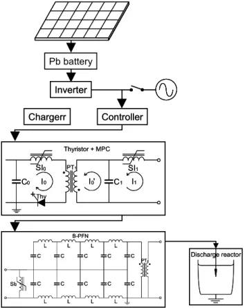
A block diagram of a repetitive pulsed power system that we have developed is shown in Figure 2. This mobile system consists of a photo-voltaic generator, a Pb battery, a dc/ac inverter, a controller, a command charger, a high-speed thyristor, a MPC, a Blumlein type pulse forming network (B- PFN), and a pulse transformer.
The photo-voltaic generator has a maximum electric power of 200 W. The electric power generated with the photo-voltaic generator is stored in the Pb battery with a dc voltage of 24 V.
The dc power stored in the Pb battery is inverted to ac 200 V by using the dc/ac inverter. Commercial ac electric power can also be used directly instead of the photo-voltaic generator.
The controller supplies electricity to each module of the system and also generates the control signals. The main control signals are for the timing of charging, selection of the pulse repetition frequency and triggering the thyristor.
Furthermore, this controller functions as an abnormal state diagnostic. The charger is a high voltage power supply using a resonant inverter. The thyristor (Thy) resembles a GTO thyristor. Magnetic assist using the saturable inductor is used to switch the thyristor. The magnetic assist reduces the
voltage, peak current, and current pulse width (τ0) are 3.5 kV, 8.6 kA and 4.4 μs, respectively.
The MPC consists of a pulse transformer (PT1), saturable inductors (SI0, SI1), and low inductance capacitors (C0, C1). A Fe-based nanocrystalline magnetic core is used as the coupling core of PT1. Nanocrystalline soft magnetic alloys are used as the magnetic switches (SI0, SI1) and the pulse transformer PT1.
A charger that can provide a charge whenever the capacitor C0
requires is employed. The thyristor turns on, and then the SI0 turns on after the magnetic assist time. The current, I0, with a duration of 4.4 μs, then flows into the primary circuit. As a result, C1 is charged to a high-voltage through the PT1. At this time, SI1 acts as a current block. After charging C1, SI1 acts as a low inductance switch to discharge C1. Finally, the pulse current with a duration of about 1.8 μs is generated after the saturation of SI1. The B-PFN is charged by the output current from the MPC. The B-PFN unit consists of ceramic capacitors, inductors, a magnetic switch (SI2) and a high voltage step-up pulse transformer (PT2). The MPC is used as a charging generator for the B-PFN. The B-PFN is charged by the MPC output current.
The maximum B-PFN charging voltage is about 20 kV. The output voltage from the PT2 is over 100 kV. The typical values of the peak voltage, peak current and voltage rise time in water discharges are 108 kV, 200 ns and 1μs, respectively. The all solid-state pulsed power system, except the photo-voltaic generator, is placed in a 1 m cube box and is capable of being used outside.
Inverter
Controller Chargerr
+C0 C1
Thy PT1
SI0
I0 I '0 I1
SI1
SI2 C C L
L C C L
L C C L
L C C L
L C C PT2
B-PFN
Pb battery
Thyristor + MPC
Discharge reactor
Inverter
Controller Chargerr
+C0 C1
Thy PT1
SI0
I0 I '0 I1
SI1
SI2 C C L
L C C L
L C C L
L C C L
L C C PT2
B-PFN
Pb battery
Thyristor + MPC
Discharge reactor
Figure 2. Block diagram of an all solid state pulsed power system for water treatment.
3 GASEOUS PHASE POLLUTION CONTROL USING REPETITIVE PULSED
POWER
Non-thermal plasmas produced by a dielectric barrier discharge (= a silent discharge), a surface discharge, a dc corona discharge, and a pulsed corona discharge, have been well known to have a strong influence on activating chemical reactions in the gaseous phase. In the last few decades, researchers have tried to utilize them in many applications such as control of NOX and SOX, treatment of dioxins, removal of volatile organic compounds, generation of ozone, and excitation of excimer lasers. On the other hands, the development of the pulsed power technology has led us to use maintenance-free pulsed power generators with repetitive operation such as a magnetic pulse compressor. The generators can continuously produce large-volume non- thermal plasmas via pulsed streamer discharges. In this section, the process of pulsed streamer discharge and simulated exhaust gas treatment by pulsed streamer discharges are described.
3.1 PROCESS OF PULSED STREAMER DISCHARGES
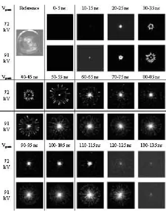
There are some literature reports which observe the results of generating pulsed streamer discharges in different conditions of applied voltage, discharge electrodes, operating gas composition and gas pressure [9-15]. Here, the process of a pulsed streamer discharge in atmospheric air is introduced as observed in our experimental results [14, 15]. Figure 3 shows the flaming emission images from pulsed streamer discharges as a function of time after the application of pulsed voltages with 72 and 91 kV peaks, and 20 ns rise time. In the experiment, a coaxial discharge electrode configuration, having a 0.5 mm in diameter central rod and 76 mm in diameter outer cylinder, is utilized to observe the pulsed streamer discharges from the axial direction. To render clear images of the pulsed streamer discharges, a short length of the discharge electrode (=10 mm) was necessary. Dry air at 0.1 MPa is introduced into the discharge chamber. A three-stage Blumlein generator with a characteristic impedance of 300 Ω is used as the pulsed power source that supplies a positive pulsed voltage with 100 ns duration to the central rod electrode. A high-speed gated ICCD camera (C7972-01, Hamamatsu Photonics, Japan) with a sensitive MCP (Micro Channel Plate, maximum gain = 10,000), is used to record the emission images from the pulsed streamer discharges during a fixed exposure time of 5 ns. The delay time of the gated ICCD camera after application of the pulsed voltage to the discharge electrode was varied in steps of 10 ns from 0 to 130 ns.
In Figure 3, the primary streamer is initiated in the vicinity of the central rod electrode (10-15 ns) and then propagates toward the grounded cylinder electrode. The time to full development of the primary streamers reduces from 55 to 40 ns with increasing peak voltages from 72 to 91 kV. This means that the higher applied voltage to the discharge
electrode results in higher average velocity of the primary streamers. During the propagation of the primary streamers in the electrode gap, the discharge current is small (~10 A). This is because the charged species largely decay by electron-ion recombination. Effectively, the capacitance between the primary streamer and the outer cylinder acts as an impedance limiting the current.
When the primary streamers lose contact with the central rod electrode, secondary streamers initiate in the vicinity of the central rod electrode since the electric field of the central rod surface becomes high enough to generate streamers with the disappearance of the interaction between the electric fields of the central rod electrode and the primary streamers. The secondary streamers propagate toward the ground electrode with higher velocity than that of the primary streamers. This is because the secondary streamers move in the plasma channels already produced by the primary streamer. The secondary streamers, however, stop propagating in the middle of the electrode gap because the electric field is insufficient to sustain the ionization once the primary streamers reach the outer cylinder electrode.
After full development of the primary streamers in electrode gap, the discharge phase changes to a glow-like discharge with a large current flow (~40-105A) in the plasma channel produced by the primary streamers. This effectively results in the disappearance of the capacitance between the primary streamers and the outer cylinder electrode.
Figure 3. Framing images of pulsed streamer discharges (Experimental conditions; Electrode gap: 38 mm, applied pulsed voltage: 72 and 91 kV Peaks, pulse duration: 100 ns)
radial direction is shown in Figure 4 as a typical streak image.
In Figure 4, a pulsed voltage of 60 kV peak is applied to the inner electrode. In Figure 4, the horizontal and the vertical axes indicate the time progression and position in the radial direction of the discharge reactor, respectively. The bottom and top of the streak image correspond to the surface of the central rod electrode and the inner surface of outer cylinder electrode, respectively. Again, the pulsed streamer discharges consist of the propagation phase of the primary and secondary streamers and the glow-like discharge phase.
10mm/div.
50ns/div.
Inner wire Outer cylinder
Primary streamer Secondary streamer
Glow-like discharge
10mm/div.
50ns/div.
10mm/div.
50ns/div.
Inner wire Outer cylinder
Primary streamer Secondary streamer
Glow-like discharge
Figure 4. Streak image of pulsed streamer discharge (Experimental conditions; Electrode gap: 38 mm, Applied pulsed voltage: 60 kV Peak, pulse duration: 100 ns)
3.2 EXHAUST GAS TREATMENT BY PULSED STREAMER DISCHARGES
Pulsed streamer discharges have been utilized to remove numerous hazardous pollutants due to the higher energy efficiency to produce chemically active radicals which react with pollutants [16, 17]. In the research field of NOX removal by pulsed streamer discharges, it is well known that a shorter pulse duration of applied voltage to the discharge reactor has a strong influence on improving the energy efficiency for reduction of pollutants [18, 19]. Here, our experimental results on NO removal by pulsed streamer discharges are discussed.
Figure 5 shows the applied voltage to the discharge reactor for different pulse durations [18]. It is observed from Figure 5 that the peak value of the applied voltage to the discharge reactor is fixed at 50 kV for the different pulse durations of 40 to 120 ns. In the experiment, a gas mixture which consists of 200 ppm of NO, 5.0 % of O2, 2.0 % of H2O, and the balance N2 at atmospheric pressure and room temperature, is used as the treated gas by pulsed streamer discharges. The flow rate is controlled at 2.0 L/min by mass flow controllers (SEC-E440J, STEC Inc., Japan). A coaxial cylindrical reactor is used as it has been shown to be more effective in producing pulsed streamer discharges due to generation of high electric fields in the vicinity of the central wire [20, 21]. The central rod, made of stainless steel, 0.5 mm in diameter, is placed concentrically in a copper cylinder having a 76 mm inner diameter and 500 mm length. The energetic electrons in pulsed streamer discharge plasmas are necessary to collide with N2, O2 and H2O to produce chemically active radicals such as N, O and OH, which react with the pollutant [20, 21]. The
analyzer (Testo350, Testo Term Co., German).
Figure 6 shows the dependence of the NO removal energy efficiency on the NO removal ratio for different pulse durations [18]. From Fig. 6, it is clear for all pulse durations that the energy efficiency of NO removal decreases with the NO removal ratio. This is because the reaction rate between radicals, produced by pulsed streamer discharges, and NO becomes lower with the progress of NO removal. On the other hands, at a fixed NO removal ratio, the NO removal energy efficiency is higher for shorter pulse durations. This means that a shorter duration pulse generates reactant radicals more efficiently. In the previous section, it was shown that pulsed streamer discharges consist of two discharge phases. The first phase is the propagation of the primary and the secondary streamers with small current flow (= small energy consumption) and the second one is the glow-like discharge with a large current flow. From the view point of the pulsed streamer discharge process, the reason why a shorter duration pulse performs better for NO removal, as shown in Fig. 6, is due to the smaller energy consumption in the glow-like discharge phase.
-40 0 40
0 100 200 300
40 ns 60 ns 80 ns 100 ns 120 ns
Voltage, kV
Time, ns
Figure 5. Voltage waveforms for different pulse durations.
0 0.5 1 1.5 2 2.5
0 20 40 60 80 100
40ns 60ns 80ns100ns 120ns
NO removal efficiency, mol/kWh
NO removal ratio, %
Figure 6. Dependences of NO removal efficiency on NO removal ratio for different pulse durations of applied voltage to the discharge reactor.
4 CLEANING OF LAKE AND DAM ALGEA BLOOM BY DISCHARGE PLASMAS IN
WATER
Phytoplankton proliferates rapidly in lakes and dams, and it appears as if a bluish-green powder is scattered on the water surface. When nitrogen and phosphorous, nutrition for
phytoplankton, flow into the lakes and dams, rapid proliferation of the phytoplankton occurs. The increase of these nutrients is mainly caused by the increase in human activity around the lakes and dams. Typical phytoplankton in lakes and dams with the eutrophication state are Anabaeba and Microcystis. A water surface with the bluish-green powder is called a water bloom.
Water bloom is ugly and smells bad. Furthermore, it changes the aquatic environment by blocking the sunlight.
Toxins have also been observed in one kind of Microcystis.
Therefore, the need to treat water bloom is a serious environmental problem all over the world. Treatments for water blooms have been investigated using chemical compounds, ultrasonic [22], microwave, electrolysis and mollusks. However, these methods are not feasible at the present time due to economical, effectiveness, and environmental reasons.
We have been researching treating water bloom by using streamer-like discharges in water which are produced by pulsed power generators [23, 24]. The prototype operated successfully at a lake near Tokyo in the summers of 2005 and 2006. Here, the results of basic experiments and at Hikawa Dam near Kumamoto are summarized.
Figure 7 shows the photograph of the state of the water surface at the dam in the summer. The dam was green in color with many floating small-green particles. From a microphotograph shown in Fig.10, it is confirmed that the small-green particles are colonies of Microcystis aeruginosa with 3.2-6.6 μm cell diameters.
Figure 7. Bluish-green powder on the water surface at a dam in the summer
Figure 8 shows the dependence of the water temperature and chlorophyll on depth from the surface. Microcystis floats near the water surface as indicated by the results of the chlorophyll measurement. The streamer-like discharges shown in Figure 9 irradiate a colony of Microcystis. The diameter of discharges is about 8 cm. A Blumlein-type pulsed forming network (B-PFN) was used to provide a 1 μs, 120 kV, 400 A pulsed power to a point electrode. The ground electrode is a basket geometry of metal mesh which is placed about 30 cm from the point electrode.
20 25 30 35
0 100 200 300 400 500
0 10 20 30 40 50 60
Water temperature Chlorophyll
Water temperatude, o C Chlorophyll, arb.unit
Depth from the surface, cm
Figuare 8. Dependence of water temperature and chlorophyll on depth from the surface
Figure 9. Photograph of streamer-like discharges in water
Figures 10a and 10b show bright-field photomicrographs of Microcystis aeruginosa before and after irradiation from streamer-like discharges respectively. In Figure 10a, the Microcystis aeruginosa have dark regions within their cellular structure. The dark regions are gas vesicles (GVs) which have a blackish appearance due to the refraction of background light. GVs are special intracellular structures of the bloom- forming cyanobacteria genus and are filled with gas. They allow Microcystis aeruginosa cells to float near the water surface in a position with optimal sunlight conditions for growth [25, 26]. Figure 10b shows the GVs disappearing after irradiation with streamer-like discharges, since the dark regions in cells are not observed. The diameter of Microcystis aeruginosa cell is about 6 μm.
Microcystis aeruginosa will sink to the bottom of the dam or lake after irradiation with streamer-like discharges.
Since the water bloom disappears after the discharges in the water, the scenery becomes better and the sunlight can penetrate deeper to maintain a healthy aquatic environment.
Furthermore, the Microcystis aeruginosa cells that sink to the bottom of dam or lake cannot proliferate. Figures 11a
entire apparatus and for the discharge component in water, respectively. The pulsed power is generated by a Blumlein- type pulsed forming network (B-PFN) charged by a solar battery. Details of the product development for the treatment of water bloom will be described in another paper.
(a)
(b)
Figure 10. Bright-field photomicrographs of Microcystis aeruginosa (a) before and (b) after irradiation by streamer-like discharges in water
5 RECYCLING OF CONCRETE BY PULSED POWER
The percentage of recycled concrete scrap has been kept over 98% in Japan since the Law for the Recycling of Construction Materials was enforced in 2000. Presently, most concrete scrap is recycled as a lower sub-base coarse material.
(a)
(b)
Figure 11. Photographs of experimental setup for (a) the entire mobile apparatus and (b) the discharge component in water.
However, it is foreseen that concrete scrap will increase rapidly and exceed the demand of road sub-base in the near future. The technology to produce high quality recycled coarse aggregate must be developed to keep the percentage of recycled concrete scrap high. Heating and rubbing is one developed method of producing recycled aggregate. However, the problem is that too much energy is consumed to heat and rub the concrete.
We have been researching using electrical discharges in the bulk concrete, which is placed in water, in order to create high quality recycled aggregate. An in-house-made Marx generator (0.80 µF-40 kV, 10 stages) has been used to make the discharges in the concrete. The method is similar to the fragmentation of granite [27-29]. Here, basic experimental results and characteristics of recycled aggregate are summarized.
Figure 12 shows the experimental apparatus to remove the recycled coarse aggregate from a block of concrete. The copper electrode, with a 5 mm diameter, makes contact with concrete by means of a spring. The ground electrode is made of 5 mm stainless mesh. The smaller fragments from the concrete, less than 5 mm in size, fall through the mesh down into the water vessel. The concrete is immersed in tap water to avoid discharging into the surrounding air.
Insulator
Concrete Hemisphere mesh (GND)
Rod H.V.
electrode
Tap water 25 mS/m Spring
Guard fence Guard fence
Water level
Water vessel
300 mm
150 mm
Insulator
Concrete Hemisphere mesh (GND)
Rod H.V.
electrode
Tap water 25 mS/m Spring
Guard fence Guard fence
Water level
Water vessel
300 mm
150 mm
(a)
Concrete
Hemisphere mesh (GND) Rod H.V.
electrode
Tap water 25 mS/m Water vessel 300 mm
300 mm
Concrete
Hemisphere mesh (GND) Rod H.V.
electrode
Tap water 25 mS/m Water vessel 300 mm
300 mm
(b)
Figure 12. (a) Side and (b) top views of experimental setup to recycle coarse aggregate.
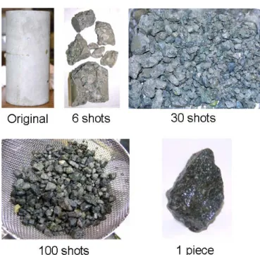
Figure 13 shows the amount of fragmentation after different shot numbers. When pulsed power with 400 kV and 8 kA is applied to the block of concrete six times, the concrete is separated into seven pieces. The concrete is separated into smaller fragments with increasing number of shots. High quality aggregate is produced after about one hundred shots.
For comparison, the face dry density, bone dry density and water absorption ratio of the recycled aggregate were measured for the original aggregate and aggregate removed from concrete by pulsed power, heating and rubbing, and mechanical crashing. The characteristics of the aggregate removed by pulsed power are nearest to that of the original aggregate.
Figures 14a and 14b show photographs of a discharge and concrete scooped out by discharges, respectively. Two electrodes with 15 cm separation are in contact with the surface of concrete. One electrode is ground and the pulse is applied to the other. The concrete and the tips of the electrodes are immersed in tap water. The discharge light is observed only near the contact regions between the concrete and two electrodes. Since no light is observed between the two electrodes, but a high current flow is observed, we conclude that the discharge must occur inside the concrete.
Figure 13. Amount of fragmentation for different shot numbers.
(a)
(b)
Figure 14. Photographs of (a) discharge and (b) concrete scooped out.
In order to understand why the discharge occurs inside the concrete, we placed the concrete in a vacuum for 24 hours, and then in water for 100 h. We note that air exists inside the concrete initially. Therefore after these treatments, the air near the concrete surface is replaced by water. Figure 15 shows the
treated and untreated concrete. The treated concrete is not fragmented at all. It is concluded that the air inside concrete plays an important role for discharges inside concrete. Figures 16a and 16b shows the discharge light emission for treated and untreated concrete, respectively. We can clearly see that discharges occur inside concrete in the case of untreated concrete and on the surface in the case of treated concrete.
0 5 10 15 20 25 30 35
0 2 4 6 8 10 12
未処理コンクリート 水浸透コンクリート
破砕 量 [c c]
ショット数
Fragmentation area, cc
Number of shots, shots
● Untreated
■ Treated
0 5 10 15 20 25 30 35
0 2 4 6 8 10 12
未処理コンクリート 水浸透コンクリート
破砕 量 [c c]
ショット数
Fragmentation area, cc
Number of shots, shots
● Untreated
■ Treated
Figure 15. Dependence of the fragmentation area on the number of shots for treated and untreated concrete.
(a)
(b)
Figure 16. Discharge light emission for (a) treated and (b) untreated concrete.
6 SUMMARY
All solid-state pulsed power generators with a high repetition rate, high stability and long lifetime have been developed for commercial applications. A magnetic pulse compressor has been used in exhaust gas treatment and an ozonizer. The Blumlein type pulse forming network charged by a magnetic pulse compressor was developed for producing discharge plasmas in water. A photo-voltaic generator as a primary power source is used for a mobile pulsed power generator which has been used in the clearing of algae bloom on lakes and dams.
Research stimulated for environmental applications has led to successful development of pulsed power generators optimized for different environmental applications. Gaseous phase pollution control using pulsed power, cleaning of lake and dam by discharges in water and recycling of concrete by pulsed power have been developed toward industrial applications.
REFERENCES
[1] W. Partlo, R. Sandstrom and I. Fomenkov, “A low cost of ownership KrF excimer laser using a novel pulse power and chamber configuration”, Intern. Society for Optical Engineering-SPIE , Vol.
2440, p.90, 1995
[2] H. Mizoguchi, O. Wakabayashi, T. Aruga, T. Sakugawa and T.
Koganezawa, “High power KrF excimer laser with a solid state switch for microlithography”, Intern. Society for Optical Engineering-SPIE, Vol. 2726, pp. 813-840, 1996
[3] S. Katsuki, A. Kimura, S. Akiyoshi, H. Fukumoto, H. Horita, T.
Namihira and H. Akiyama, “Z-pinch discharge based EUV radiation source driven by a low-inductance gap-less circuit”, Proc. 26th Intern.
Power Modulator Symposium and 2004 High Voltage Workshop, pp.322-325, 2004.
[4] T. Namihira, S. Tsukamoto, D. Wang, S. Katsuki, R. Hackam, H.
Akiyama, Y. Uchida and M. Koike, “Improvement of NOx removal efficiency using short width pulsed power”, IEEE Trans. Plasma Sci., Vol. 28, pp.434-442, 2000.
[5] W. J. M. Samaranayake, Y. Miyahara, T. Namihira, S. Katsuki, T.
Sakugawa, R. Hackam and H. Akiyama, “Pulsed streamer discharge characteristics of ozone production in dry air”, IEEE Trans. Dielectr.
Electr. Insul., Vol. 7, pp.254-260, 2000.
[6] T. Sakugawa, D. Wang, K. Shinozaki, T. Namihira, S. Katsuki and H.
Akiyama, "Repetitive short-pulsed generator using MPC and blumlein line”, IEEE 14th Pulsed Power Conf., pp. 657-660, 2003.
[7] H. Akiyama, T. Fudamoto, S. Katsuki, T. Namihira and T. Sakugawa,
“Industrial Applications of Pulsed Power”, IEEJ Trans. FM, Vol. 125, pp.717-722, 2005
[8] T. Sakugawa and H. Akiyama, “An all-solid-state pulsed power generator using a high-speed gate-turn-off thyristor and a saturable transformer”, Electrical Engineering in Japan, Vol. 140, No. 4, pp.17-26, 2002
[9] K. Yan, H. Hui, M. Cui, J. Miao, X. Wu, C. Bao and R. Li, “Corona induced non-thermal plasma: Fundamental study and industrial applications”, J. Electrostatics, Vol.44, pp.17-39, 1998.
[10] K. Yan, S. Kanazawa, T. Ohkubo and Y. Nomoto, “Evaluation of NOX removal by corona induces non-thermal plasma”, Trans. Institute of Electrical Engineers of Japan, Vol.119-A, pp.731-737, 1999.
[11] E.H.W.M. Smulders, B.E.J.M. van Heesch and S.S.V.B. van Passen,
“Pulsed power corona discharges for air pollution control”, IEEE Trans.
Plasma Sci., Vol.26, pp.1476-1484, 1998.
[12] W.J. Yi, S.J. Hankla and P.F. Williams, “High-temporal-resolution, high-sensitivity imaging of streamers in a long atmospheric pressure gap”, IEEE Trans. Plasma Sci., Vol.24, pp.93-94, 1999.
[13] E.M. van Veldhuizen, P.C.M. Kemps and W.R. Rutgers, “Streamer branching in a short gap: The influence of the power supply”, IEEE Trans. Plasma Sci., Vol.30, pp.162-163, 2002.
[14] T. Namihira, D. Wang, S. Katsuki, R. Hackam and H. Akiyama,
“Propagation velocity of pulsed streamer discharges in atmospheric air”, IEEE Trans. Plasma Sci., Vol.31, pp.1091-1094, 2003.
[15] D. Wang, M. Jikuya, S. Yoshida, T. Namihira, S. Katsuki and H.
Akiyama, “Observation of pulsed streamer discharges in atmospheric air using sub-microsecond pulse generator”, IEEE 15th Intern. Pulsed Power Conference, Monterey, USA, 2005. (in print)
[16] J.S. Chang, P.A. Lawless and T. Yamamoto, “Corona discharge process”, IEEE Trans. Plasma Sci., Vol.19, pp.1152-1166, 1991.
[17] R. Hackam and H. Akiyama, “Air pollution control by electrical discharges”, IEEE Trans. Dielectr. Electr. Insul., Vol.7, pp.654-683, 2000.
[18] T. Namihira, S. Tsukamoto, D. Wang, S. Katsuki, R. Hackam, H.
Akiyama, Y. Uchida and M. Koike, “Improvement of NOX removal efficiency using short width pulsed power”, IEEE Trans. Plasma Sci., Vol.28, pp.434-442, 2000.
[19] V. Puchkarev and M. Gundersen, “Energy efficient plasma processing of gaseous emission using a short pulse discharge”, Appl. Phys. Letter, Vol.71, No.23, pp.3364-3366, 1997.
[20] R. Hackam, “Total secondary ionization coefficient and breakdown potentials of hydrogen, methane, ethylene, carbon monoxide, nitrogen, oxygen and carbon dioxide between mild steel coaxial cylinders”, J.
Phys. B: Atom. Molec. Phys. (UK), Vol.2, pp.216-233, 1969.
[21] R. Hackam, “Total secondary ionization coefficients and breakdown potentials of monatomic gases between mild steel coaxial cylinders”, Journal of Physics B: Atom. Molec. Phys. (UK), Vol.2, pp.201-215, 1969.
[22] H. Hao, M. Wu, Y. Chen, J. Tang and Q. Wu, “Cyanobacterial bloom control by ultrasonic irradiation at 20 kHz and 1.7 MHz”, J.
Environmental Science and Health, Part A: Toxic/Hazardous Substances
& Environmental Engineering, Vol.39, No.6, pp.1435-1446, 2004.
[23] H. Akiyama, “Streamer discharge in liquids and their applications”, IEEE Trans. Dielectr. Electr. Insul., Vol.7, pp.646-653, 2000.
[24] Z. Li, S. Sakai, C. Yamada, D. Wang, S. Chung, X. Lin, T. Namihira, S.
Katsuki and H. Akiyama, “The Effects of Pulsed Streamerlike Discharge on Cyanobacteria Cells”, IEEE Trans. Plasma Sci., Vol. 34, pp.1719- 1724, 2006.[25] A. Howard, “Problem cyanobacteria blooms:
explanation and simulation modeling”, Trans. Institute of British Geographers, Vol.19, No. 2, pp.213-224, 1994.
[25] A. Howard, “Problem cyanobacteria blooms: explanation and simulation modeling”, Trans. Institute of British Geographers, Vol.19, No. 2, pp.213-224, 1994.
[26] A. Mlouka, K. Comte, A. Castets, C. Bouchier and N. Marsac, “The gas vesicle gene cluster from microcystis aeruginosa and DNA rearrangements that lead to loss of cell buoyancy”, J. Bacteriology, Vol.186, pp.2355-2365, 2004
[27] I.V. Lisitsyn, T. Muraki and H. Akiyama, “Mechanism of shock waves generation and material destruction in a wire induced surface flashover”, Physica B, Vol.239, pp.6-8, 1997.
[28] H. Inoue, I.V. Lisitsyn, H. Akiyama and I. Nishizawa, “Pulsed Electric Breakdown and Destruction of Granite”, Japanese J. Appl. Phys., Vol.38, pp.6502-6505, 1999.
[29] H. Inoue and I. V. Lisitsyn, H. Akiyama. I. Nishizawa, “Drilling of Hard Rocks by Pulsed Power”, IEEE Electr. Insul. Mag., Vol.16, No.3, pp.19- 25, 2000
Hidenori Akiyama (M’87–SM’99–F’00) received the Ph.D. degree from Nagoya University, Nagoya, Japan, in 1979. From 1979 to 1985, he was a Research Associate at Nagoya University. In 1985, he joined the faculty at Kumamoto University, Kumamoto, Japan, where he is currently a Professor. He received the IEEE Major Education Innovation Award in 2000 and the IEEE Peter Haas Award in 2003.
Shunsuke Sakai was born in Kumamoto, Japan, on 22 July 1983. He received the B.S degree from Kumamoto University, Kumamoto, Japan in 2006, and is currently pursuing the M.S. degree there.
Takaishi Sakugawa (M’00) received the M.E.
degree from Kyushu University, Japan, in 1989 and the D.E degree from Kumamoto University, Japan, in 2004. He worked at Meidensha Corporation from 1989 until 2004. He has been an associate professor in Kumamoto University. He is a Member of the Laser Society of Japan, the Institute of Electrostatics Japan, JSAP..
Takao Namihira (M’00-SM’05) was born in Shizuoka, Japan, on 23 January 1975. He received the B.S., M.S., and Ph.D. degrees from Kumamoto University, Kumamoto, Japan, in 1997, 1999, and 2003, respectively. From 1999 to 2006, he was a Research Associate at Kumamoto University, where he is currently an Associate Professor. During 2003-2004, he was on sabbatical leave at the Center for Pulsed Power and Power Electronics, Texas Tech University, Lubbock, USA.
![Figure 5 shows the applied voltage to the discharge reactor for different pulse durations [18]](https://thumb-ap.123doks.com/thumbv2/123deta/5654010.2005967/5.918.527.791.483.694/figure-shows-applied-voltage-discharge-reactor-different-durations.webp)