Behavior of high-nickel type weathering steel bars in simulated pore solution and mortar
under chloride-containing environment
(塩化物イオン環境下での高ニッケル型耐侯性鋼棒 の模擬細孔溶液およびモルタル中における挙動)
by
EMEL KEN D. BENITO (Student No.: 18851531)
Supervisor
Assoc. Prof. Atsushi UENO
A manuscript submitted in partial fulfilment of the requirements for the Degree of Master of Engineering
in Civil and Environmental Engineering
Department of Civil and Environmental Engineering Graduate School of Urban Environmental Sciences
Tokyo Metropolitan University
March 2020
TABLE OF CONTENTS
1. Introduction ... 1
1.1. Background of the Study ... 1
1.2. Current Approach on Corrosion Prevention ... 3
1.3. Problem Statement and Research Significance ... 5
1.4. Objective of the Study ... 6
1.5. Limitation of the Study ... 6
1.6. Research Outline ... 6
REFERENCES ... 9
2. Related Literature ... 10
2.1. Corrosion in Reinforced Concrete ... 10
2.1.1. Basic concepts ... 10
2.1.2. Chloride-induced corrosion ... 11
2.1.3. Effect of corrosion in reinforced concrete ... 12
2.2. Electrochemical Aspects of Corrosion ... 14
2.2.1. Corrosion Thermodynamics: Equilibrium potential ... 14
2.2.2. Corrosion Kinetics: Corrosion rate and Polarization curve ... 17
2.2.3. Mechanism of half-cell potential measurement in concrete ... 19
2.2.4. Factors affecting the corrosion potential ... 23
2.3. Rebar Passivation by Concrete ... 25
2.3.1. Alkalinity ... 25
2.3.2. Resistance to fluid intrusion ... 26
2.4. Passive Film and Protective Rust ... 28
2.5. Weathering Steel ... 29
2.5.1. Historical development ... 29
2.5.2. Corrosion mechanism of conventional WS in nanoscopic level ... 33
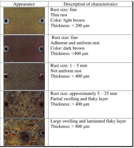
2.5.3. General properties of rust layer ... 35
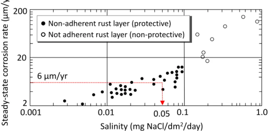
2.5.4. Conventional weathering steel under mild environment ... 39
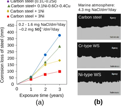
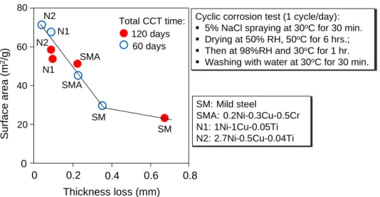
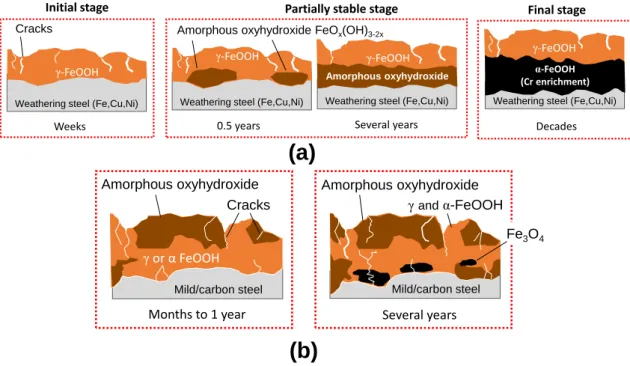
2.5.5. Mechanism of rusting in marine environment ... 42
2.5.6. General requirements for developing the protective layer ... 49
2.6. Related Studies on the Application of Weathering Steels... 50
2.6.1. Simulated pore solution ... 50
2.6.2. Concrete element ... 53
2.6.3. Behavior of weathering steels based on potential measurement ... 56
2.7. Conclusion ... 59
REFERENCES ... 61
3. Progress of Corrosion on High-Nickel Type Weathering Steel Bars in Simulated Pore Solution ... 67
3.1. Introduction ... 67
3.2. Experimental Outline ... 67
3.2.1. Materials ... 67
3.2.2. Cleaning and evaluation of test specimens ... 70
3.3. Results and Discussion ... 74
3.3.1. Effect of alkalinity ... 74
3.3.2. Effect of oxygen ... 75
3.3.3. Effect of steel type ... 76
3.4. Summary and Conclusion ... 82
REFERENCES ... 83
4. Behavior of High-Nickel Type Weathering Steel Bars Embedded in Mortar under Chloride-containing Environment ... 84
4.1. Introduction ... 84
4.2. Materials ... 84
4.2.1. Steel bars ... 84
4.2.2. Mortar ... 85
4.2.3. Plastic mold ... 85
4.3. Experimental Outline ... 86
4.3.1. Experimental design ... 86
4.3.2. Specimen preparation ... 88
4.3.3. Exposure condition ... 89
4.3.4. Measurement methods ... 91
4.4. Results and Discussion ... 94
4.4.1. Influence of wet-dry cycle on Ecorr ...94
4.4.2. Influence of crack on Ecorr ... 96
4.4.3. Influence of steel type on Ecorr ... 96
4.4.4. Surface condition ... 98
4.4.5. Corrosion depth ... 99
4.5. Summary and Conclusion ... 104
REFERENCES ... 105
5. Conclusion ... 106
5.1. Summary of Results in Simulated Pore Solution ... 106
5.2. Summary of Results in Mortar Test ... 106
5.3. Direction of Future Research ... 108
ACKNOWLEDGEMENT ... 110 APPENDIX
1
Chapter 1
Introduction
1.1. Background of the Study
Metals, like all materials, naturally undergo deterioration through time as a result of their interaction with surrounding environment. They do not occur in their pure form in nature because they are normally bounded to other substances in ores. Under processing and purification in plants, they are purified, but in return, they become thermodynamically unstable. Through time, they will tend to revert back to their natural state (i.e. lowest energy), composed of oxides and hydroxides, or other basic compounds.
They do this by way of corrosion. The phenomenon is a very slow process and involves movements of small particles, e.g. electrons and ions. However, when uncontrolled, excessive corrosion can cause damage just as severe as natural hazards such as earthquake or weather disturbances.
Corrosion is considered to be the most common cause of deterioration in any types of construction today 1. On one hand, it requires tedious maintenance and rehabilitation that entail a great deal of monetary expenditure. In the most recent study2 on the cost of corrosion (COC) by the National Association of Corrosion Engineers (NACE International) in 2016, it is estimated that the global economy spends about $2.5 Trillion annually, which is equivalent to 3.4% of the world’s Gross Domestic Product (GDP) in 2013. Of this amount, the industry sector accounts for more than half of the total expenditure (see Figure 1-1). This sector includes cost of repairing and replacing damaged components in mining, manufacturing and construction industries. On the other hand, major accidents that were linked to corrosion resulted to countless number of lives lost, destruction of environment, and productive opportunities taken away. Petrović 3 in his review observed that corrosion-related causes account for more than 40% of structural failures worldwide. In turn, corrosion has been dubbed as “the largest single infrastructure problem facing industrialized countries” 4.
2
Figure 1-1. Data of cost of corrosion per country. Abbreviated: HK = Hong Kong, TW = Taiwan, KR = South Korea, SG = Singapore; MO = Macao
The last hundred years saw the rise of reinforced concrete as the most prominent material for construction. Combining steel and concrete comes with three notable advantages: (1) the two materials have nearly the same thermal properties; (2) they complements in resisting the combined effect of tension and compression; and, (3) the physical presence and alkalinity of concrete cover provides a protective barrier to steel, which corrodes easily in the presence of moisture. However, since corrosion is inevitable, the very presence of metal inside a concrete makes the composite vulnerable to damage due to aging and environmental factors, primarily in the presence of moisture. In advanced stages, the load-bearing capacity of structure may be significantly reduced resulting to termination of its service life.
Corrosion inevitably comes with the age of structure and, thus, the increased risk of failure. In Japan, historical data of constructed bridges, with length 15m or more, shows that the number peaked during the time of rapid economic growth between 1960s and 1980s (Fig. 1-2). Aging structures will increase at an alarming rate in few decades.
The Ministry of Land, Infrastructure, Transport, and Tourism (MLIT) estimated that bridges with age 50 years or older will account for 43% of all constructed in 2023, and about 67% in 2033 5. In this respect, the effort to repair and replace these structures become increasingly significant, especially against the deteriorating effect of corrosion.
However, from the standpoint of economy and productivity, prevention should be prioritized than repair as the former option provides a better life-cycle design performance, because unlike natural hazards, corrosion is controllable. Under these considerations, developing ways to prevent and manage the deterioration of aging structures by corrosion is imperative for modern engineers and researchers.
0.0 1.0 2.0 3.0 4.0 5.0 6.0
0 200 400 600 800
Japan HK, TW, SK, SG,
MC
India Russia Arab World
China USA Rest of the World
Europe
% GDP of COC
Cost of corrosion (in Billion USD)
Services Industry Agricultural
%GDP
3
Figure 1-2. Yearly distribution of road bridges in Japan showing aging structures in the next decades. Data adapted from Kuwabara et al. 5
1.2. Current approach on Corrosion Prevention
Corrosion is either chloride-induced or carbonation-induced. Of these two, corrosion by chloride attack causes the most severe damage almost all of the time, especially in areas near the coastline. In recent years, much of research effort has been oriented towards the control of this problem. But regardless of mechanism, strategies currently known to control the process can be grouped according to three broad categories 6:
(1) Application of corrosion inhibitors (e.g. galvanization or stainless steel covering) and surface coatings (e.g. epoxy or ceramic coating);
(2) Installation of cathodic protection systems by connecting sacrificial anodes that exhibits lower electrochemical potential than the protected metal;
(3) Use of corrosion-resistant bare metals, so called weathering steels.
The first two approaches are merely counteractive in which, instead of the metal, an external system is applied to interfere with the corrosive agents. These approaches, however, require periodic monitoring of the system being applied, and they can be compromised due to the unpredictable nature of attack and its source. An ideal solution is still to use metals that are by themselves resistant against chloride attack 7.
Weathering steel (WS) was the result of large-scale research program around the world during the second half of 20th century with the aim to extend the useful life and reduce the life-cycle cost of infrastructures by relying primarily on the ability of material
1,000 2,000 3,000 4,000 5,000 6,000
30,000 60,000 90,000 120,000 150,000 180,000
0 0
▌Prestressed Concrete Reinforced Concrete
▌Steel Total
Total (cumulative) No. of Bridges
Number of Bridges
Construction Year
50 years and older (2020)
50 years and
older (2030) 50 years and older (2040)
4
to protect itself. The alloying elements in mild or carbon steel are increased and modified to a lesser extent so as to alter the evolution of rust during wet-dry cycle leading to development of a dense and well-adhering rust layer over several years of exposure (generally ≥ 5 years). Elements normally used as alloys are carbon (C), copper (Cu), chromium (Cr), nickel (Ni), phosphorous (P), silicon (Si) or manganese (Mn). They are added only at small concentrations from 3 to 5 wt. %, making them a more viable alternative to the expensive stainless steels.
The significance of WS can be further realized in various ways. First, the layer itself act as a barrier against further ingress of aggressive ions, eliminating the need of surface coating and thereby reducing the overall life cycle cost of a structure. In addition, increasing the alloys improves the mechanical properties of steel (i.e. yield strength, ultimate strength and hardness), reducing the required cross-section for the same service load. Finally, the protective rust has a secondary effect of increasing the aesthetic value of a structure owing to its attractive rusty appearance. Thus, WS has been gaining popularity in recent decades as a promising structural material, particularly for bridges, to realize extended service life, improved structural performance with thinner member section that compensates the initial cost of acquiring rare metals. Fig. 1-3 illustrates the significant advantage of the material over conventional method in terms of life cycle cost throughout the usable service of bridges in Japan.
Figure 1-3. Life-cycle cost of using weathering steel compared to conventional painting maintenance 8.
20 40 60 80 100
10 20 30 40 50
- -Painted steel - -Weathering steel
Life cycle cost (relative)
Time (years)
Case with inspection only Case with partial repairs, etc.
Social Value
Securing Longevity by Minimum Maintenance
5
1.3. Problem Statement and Research Significance
Weathering steel was introduced to Japan during 1960s. The alloy composition from which it was derived are based from the combination of Fe, Cu, Cr, and P originally adopted by US Steel Corp. at the time. Among these alloys, Cu and Cr in particular played the most significant role. Early versions of WS put emphasis on these two components to significantly improve the corrosion resistance in atmosphere. Unlike USA, however, Japan is a relatively smaller country, which increases the influence of surrounding seawater. Near coastal plains where salt concentration in air is very high, the protective rust does not always develop as expected owing to thick corrosion products that forms with lamellar exfoliation. A new type of weathering steel was introduced in 1997 by Nippon Steel Co. in response to the need of greater resistance against salt corrosion. The material was developed on the basis of increasing the weight percentage of Ni and elimination of Cr while maintaining the Cu content.
While the Ni-type weathering steel has been extensively studied and used in relation to open exposure conditions and alternating wet-dry environment, there is still no published literature currently available that explicitly described its implications when used in cement-based material. Thus, the motivation that makes up this study is pointed out in the following research gaps:
(1) Data on the durability performance of weathering steels under highly alkaline and low-oxygen environment is still lacking;
(2) Information on the development of protective rust when confined in cement- based material is still unknown.
A well-cured concrete has very low permeability, and a very high pH owing to the formation of Ca(OH)2 and other alkaline ions in the process of cement hydration. These conditions produce a very thin (< 10 nm) insoluble film of iron oxide that protects the embedded steel from dissolving. The passive film can be destroyed at a contact with aggressive ions, such as chlorides, which instigates corrosion. It is hypothesized that alloys included in WS may facilitate the growth of compact and well-adhering rust layer when the corrosion starts; thus providing necessary protection against further damage.
In order to provide evidence on the use of weathering steel as a more economical reinforcement of concrete, it is necessary to conduct a basic study on the behavior of the material in mediums that simulates this condition. Understanding the research gaps
6
pointed above will advance the current knowledge with regards to the application of weathering steel, which can be used to develop new design principles for creating more durable and efficient materials in the future.
1.4. Objective of the Study
An experimental program was designed to study the beahvior and rust formation of the newly developed WS with about 1.0 wt. % Ni, relative to the conventional WS containing 1.0 wt. % Cr and ordinary carbon steel. The specific objectives of this study are:
(1) Provide baseline data with regards to corrosion progression of Ni-containing weathering steel in solution with varying amount of oxygen and pH to simulate the condition in concrete under chloride attack.
(2) Provide information on short-term behavior of Ni-containing weathering steel in embedded in mortar with or without crack under chloride-containing environment.
1.5. Limitation of the Study
The protective rust on the surface of bare weathering steels appears over the period that a structure is under service condition. This period covers the greater part of a structure’s entire service life, which realistically speaking, could take several decades.
However, with limitation of time, the experiment was only conducted over several months. To account for this short time, chloride was used to accelerate the rusting process and obtain an appreciable damage within the period allowed by the study. This is the usual approach taken by many authors dealing with laboratory exposure test of weathering steel, such as those cited in references 9–13.
1.6. Research Outline
The chapters that constitute this study is summarized as follows.
Chapter 1 outlines the background from which the present study was derived, the significance of conducting the research and corresponding objectives.
Chapter 2 establishes the underlying principles and concepts of corrosion in reinforced concrete. Before studying the characteristics of rust that forms in weathering
7
steel (WS), it is necessary to understand the electrochemical nature of corrosion. Then, the development of the material and mechanism of its rusting, relevant to the understanding of their behavior in concrete, are reported according to a wealth of information available in literature. Finally, some early and recent studies around the world concerning low-alloy and weathering steels were also presented, giving emphasis to the insufficient researches made so far in cement-based materials.
Chapter 3 reports the result of basic test involving 168 small pieces of steel bars exposed to simulated liquid over a period of 150 days. The liquid phase is composed of 3.5% NaCl solution with and without NaOH to achieve alkaline and acidic pH. Oxygen content was changed by complete immersion, wet-dry cycle, and continuous aeration of liquid. Average penetration depth, evaluated from mass loss after exposure, was used as the main index of durability. Results indicate that corrosion depth increases as oxygen content increases or as pH decreases, consistent with the established electrochemical theory of corroding steel. The result further suggests that high-Cr WS has lower penetration when oxygen is abundant, but no remarkable change when oxygen is depleted. On the other hand, high-Ni WS showed slightly lower corrosion than other steels only when exposed to periodic drying and acidic electrolyte, conditions that are found primarily in atmospheric environment. Finally, high-Ni WS was found to have no clear influence in environment that remains continuously wet, is highly alkaline or has very low oxygen. The first item is explained by the fact that corrosion products grow rapidly and become loosely adhering with continuous wetting in chloride-containing water. Under high pH or depleted oxygen, corrosion rate is usually very low regardless of steel composition. Thus, the behavior of weathering steel become practically the same as that of ordinary steels.
Chapter 4 discusses the result of the experimental program conducted on similar sets of metals embedded in mortars. A series of reinforced cylindrical mortars with or without cracks were made having w/c of 0.60. They were exposed to wet-dry cycle under 3.5% NaCl solution. Half-cell potential method was used as a non-destructive means to assess the progress of corrosion of embedded steels. Corroded area and average corrosion depth, based on mass loss, were also evaluated to determine the actual degree of damage for a total period of 120 days. While the data of corrosion potential (Ecorr) and rusted area indicate that steel type seems to have no remarkable influence, the trend of corrosion depth reveals that Ni-type WS actually sustained slightly higher penetration. The latter
8
result does not seem to coincide with that of liquid phase, which is considered to be due to the difference in distribution of chloride ions present in each phase. It appears, therefore, that high-Ni type WS is relatively more susceptible to penetration when rust is still localized and only covers small areas. However, high-Ni type WS is known for its superior resistance owing to the appearance of a dense and uniform rust layer. The computed values of corrosion depths were merely less than 30 μm. Since rust that formed was still few and localized, the said amount is still significantly small relative to the values when rust is fully grown and uniform. Thus, the behavior of Ni-type WS bars in mortar may still be considered practically the same as those of conventional steels.
Chapter 5 summarizes the result this study, as well as provides recommendations for future research and development
9
REFERENCES
1. Bertolini, L., Elsener, B., Pedeferri, P. & Polder, R. Corrosion of Steel in Concrete:
Prevention, Diagnosis, Repair. (Wiley-VCH Verlag GmbH & Co. KGaA, 2004).
2. Gerhardus, K. et al. International Measures of Prevention , Application , and Economics of Corrosion Technologies Study. 1–216 (2006).
3. Petrović, Z. C. Catastrophes caused by corrosion. Mil. Tech. Cour. 64, 1048–1064 (2016).
4. Broomfield, J. P. Corrosion of Steel in Concrete: Understanding, Investigation and Repair. (Taylor and Francis, 2007).
5. Kuwabara, T. et al. Outline of Japanese Design Specifications for Highway Bridges in 2012. (2012).
6. Albrecht, P. & Hall, T. T. Atmospheric Corrosion Resistance of Structural Steels. J.
Mater. Civ. Eng. 15, 2–24 (2003).
7. Winslow, D. N. High-strength low-alloy, weathering, steel as reinforcement in the presence of chloride ions. Cem. Concr. Res. 16, 491–494 (1986).
8. Kihira, H. & Kimura, M. Advancements of weathering steel technologies in Japan.
Corrosion 67, 095002-1-095002–13 (2011).
9. Wen, C., Tian, Y., Wang, G., Hu, J. & Deng, P. The influence of nickel on corrosion behavior of low alloy steel in a cyclic wet-dry condition. Int. J. Electrochem. Sci. 11, 4161–4173 (2016).
10. Shi, J., Wang, D., Ming, J. & Sun, W. Long-term electrochemical behavior of low- alloy steel in simulated concrete pore solution with chlorides. J. Mater. Civ. Eng. 30, 1–11 (2018).
11. Zhao, Q. H. et al. Effect of small content of chromium on wet-dry acid corrosion behavior of low alloy steel. Acta Metall. Sin. English Lett. 30, 164–175 (2017).
12. Wu, W., Zeng, Z., Cheng, X., Li, X. & Liu, B. Atmospheric Corrosion Behavior and Mechanism of a Ni-Advanced Weathering Steel in Simulated Tropical Marine Environment. J. Mater. Eng. Perform. 26, 6075–6086 (2017).
13. Ishikawa, T., Yoshida, T., Kandori, K., Nakayama, T. & Hara, S. Assessment of protective function of steel rust layers by N2 adsorption. Corros. Sci. 49, 1468–1477 (2007).
10
Chapter 2
Related Literature
2.1. Corrosion in reinforced concrete
2.1.1. Basic concepts
Corrosion is an electrochemical process defined as an exchange of electrons between two co-existing reactions, called the anodic (dissolution of metal) and cathodic (reduciton of oxygen to hydroxyl ions) reactions. Depending on electrochemical potential and pH of pore liquid, iron atom can evolve into different products by giving off electrons according to the following anodic reactions 1:
(2.1) (2.2) (2.3) (2.4) The electrons released in the oxidation (Eqs. 2.1 to 2.4) will flow towards the cathode surface, thereby supporting the progress of the following cathodic reactions 1:
(2.5) (2.6) If these reactions would remain separated, there would be no corrosion. For corrosion to proceed, a close circuit between two sets of reactions must exist causing an electronic current to flow from anodic region towards the cathodic region, as shown in the simplified schematic diagram in Fig. 2-1(a). In reinforced concrete (RC), this connection is provided either by the steel surface, concrete itself, or external components, say stirrups. The metal is left as a positively charged ion in the anode attracting the negatively charged hydroxides from the cathode, creating an ionic current (Fig. 2-1(a)).
The products will meet and precipitate into the most basic corrosion product, ferrous hydroxide Fe(OH)2. The swelling of this phase will occur as a result of progressive interaction between iron, dissolved oxygen (O2), and moisture (H2O) following a series of chemical reactions:
11
(2.7)
(2.8)
∙ (2.9)
Figure 2-1. (a) Simplified schematic of corrosion process in embedded rebar; (b) Unit volume occupied by rust phases normally found in reinforced concrete (Figure adapted from Mehta & Monteiro 2).
2.1.2. Chloride-induced corrosion
Hydrated Portland cement concrete pore system has highly alkaline due to the presence of relatively insoluble hydrates of calcium , such as calcium silicate hydrate (C- S-H), calcium hydroxide and calcium sulfo-aluminate hydrates. The presence of minor alkaline compounds such as NaOH and KOH brings the pH of the pore solution between 12.5 and 13.5 2. At this range, the interaction of OH– in concrete and iron from embedded elements gives rise to a very thin iron-oxide film on the surface of ordinary steel materials with thickness typically less than 10 nm 3. The oxide layer is commonly referred in literature as the passive film which renders the steel passive against anodic dissolution during the first few years that an RC member is under service, and can render insignificant damage 4. The film is composed of two distinct layers: a porous and non-
(a)
(b)
Fe FeO Fe3O4
Fe2O3
Fe(OH)2 Fe(OH)3
Fe(OH)3·3H2O
0 1 2 3 4 5 6 7
Relative volume
Cl¯ or CO2 O2or H2O
Rust
Fe → Fe2++ 2e¯ 1/2H2O + O2+ 2e¯→ 2OH¯
Fe2++ 2OH¯ → Fe(OH)2 Passive film (3-15 nm)
Fe2O3or Fe3O4 ionic current
Electronic current
Cathode Anode
12
protective upper layer rich in Fe3+-oxide and hydroxide, and protective bottom layer composed of Fe2+-oxyhydroxide 3. Formation of the passive film is believed to occur during the rise of pH in pore solution within the first day of hydration 5. Unfortunately, this ideal condition is not always achieved in real situations due to interplaying factors outside and inside of concrete, and corrosion remains the top cause of deterioration in RC structures. It is the destruction of this passive film that exposes the steel surface and sets the condition for damage.
There is a consensus among researchers that chloride attack is the top cause of eventual destruction of the passive layer and therefore the corrosion in reinforcing steel
6. Two theories are currently accepted explaining the mechanism by which chloride corrodes the steel in alkaline concrete. The first theory states that Cl– ion can compete with OH– ions in reacting with iron in the passive film leading to complete breakdown of the layer itself. Another theory suggest that Cl– penetrates through the porous layer of oxide film. In either scenarios, the interaction of iron with chloride gives rise to iron- chloride complexes7,8, which then proceeds with formation of rust according to either of the following reactions 7,9:
(2.10) (2.11) It can be inferred based from the above products that chlorides are not consumed in the process but are being reproduced. The reappearance of Cl– then comes with a dual consequence 6,8. First, acidity is enhanced by the reaction because hydrochloric acid ( ) is produced, which accelerates the dissolution of metal into ions. Secondly, the point of breakdown will act as anode while the surrounding passive film will act as cathode. The anodic areas inside the pits where iron is left as Fe2+ can attract Cl–, being negatively charged, which intensifies the corrosion process and gives rise to the entry of more Cl¯, which further aggravates the corrosion intensity. This vicious process of recycling makes chloride attack a major concern in RC corrosion.
2.1.3. Effect of corrosion in reinforced concrete
In normal field conditions, the rate of moisture deposition inside the concrete during wetting process is found to be greater than the rate of moisture loss during drying
10. Depending on the availability of moisture and oxygen near the steel-concrete interface, realistic rust phases normally found in RC members are composed of poorly
13
crystalline iron oxides and hydroxides as described in Fig. 2-1(b). Unlike that found in weathering steels, these type of rusts are much more expansive because of their greater tendency to absorb water. Based from the figure, individual phases can occupy a volume as much as 6 to 10 times that of the base metal. This expansion, then, displaces the surrounding concrete along the steel-concrete interface resulting in an outward radial tensile stress as high as 10 times the compressive strength of concrete 11. This volumetric increase is believed to be the primary cause of concrete cracking and spalling of RC members. Fig. 2-2(a) illustrates a simple cracking model under uniform corrosion.
Figure 2-2. (a) Cracking model of reinforced concrete assuming general corrosion (Figure adapted from Merino 12); (b) corroded reinforcement totally exposed after concrete cover underwent excessive spalling (www.msdpe.com); (c) a significant portion of concrete cover in bridge pier has been spalled away due to aging (www.bandbfrp.com).
A layer of metal, called corrosion depth, will be lost as a result of transforming iron atoms to poorly crystalline iron hydroxides. The amorphous and expansive properties of rust crystals make the layer become loosely adhering which can then be removed by mechanical or chemical cleaning. In corrosion-related studies, the depth of penetration is quantified by converting the mass that was lost as a result of removing the corrosion products using the density relationship (Eq. 2.12) and then dividing the result by the time of exposure (hours) to obtain the rate of corrosion in mm/year (Eq. 2.13) 13: (2.12) (2.13)
where = mass loss after exposure (g), = metal density (g/cm3), = area of corroding steel surface (cm2). These parameters assume that the damage is uniformly
Corrosion depth
Oxide products
crack Original steel
Initial radius Reduced radius Rust front Initial section Corroded section
(a)
(b) (c)
14
distributed over the corroded area; but in reality, attack is almost always in the form of localized pits especially for chloride-induced corrosion (Sec. 2.1.2). For comparative studies, however, such approach is well accepted.
Failure of RC structures due to corrosion is governed by two general theories: (1) the reduction of the original cross-section will lead to a decrease load-bearing capacity of the member, causing brittle failure; and (2) the volumetric expansion of oxide can lead to cracking of the surrounding concrete. Cracking will reduce the confinement of steel with the corresponding loss of bond, and in advanced stages, spalling of concrete cover, as in the cases shown in Figs. 2-2(b) and 2-2(c). Brittle failure is a major concern because structural collapse can happen without initial warning to the public using it.
2.2. Electrochemical Aspects of Corrosion
2.2.1. Corrosion Thermodynamics: Equilibrium potential
As discussed, corrosion is an electrochemical process that involves movement of electrons accompanied by chemical reactions. For an electrochemical reaction to proceed, there must be two simultaneously occurring reactions (i.e. half-cell) in which one is capable of producing electrons (anodic reaction) and another capable of consuming electrons (cathodic reaction). Consider Eq. 2.4 and Eq. 2.5 as two half-cell reactions.
Their over-all reaction when connected is given by Eq. 2.8. Assuming that the two half- cells are not connected but are allowed to proceed in two distinct surfaces. This can be done by placing an iron in a solution of ferrous ions on one side, and a platinum in a solution of hydrogen ions on the other side while being bubbled by hydrogen gas (Fig.
2-3); both interfaces being separated by a semi-permeable membrane.
Figure 2-3. Simple electrochemical cell of iron and standard hydrogen electrode.
Fe Fe2+
Fe2+
Fe2+ Pt
H+
H+ H+ Semi-permeable membrane
V Conductor
H2gas pipe
Fe2+
(-) (+)
High-resistance electrometer
15
What is happening is that in each half-cell, in the absence of external circuit, ions are dissolving and reducing at the same rate according to the following equilibrium equations:
↔ (2.14)
↔ (2.15)
The fact that there is an electron exchange means that there should be an available work between the surface and solution that allows each reaction to happen. This energy is defined by the potential difference established across the interface of individual electrodes. The potential, also known as the equilibrium or half-cell potential, is a measure of the ease of expelling or retaining an electron from a metal so that a particular reaction takes place 14,15. It is also called reversible potential because the electrode can act as anode and cathode at any given moment. In other words, without an electrical connection, the appearance and disappearance of ions in each electrode are occurring at the same rate and there is no net production or consumption of electrons, i.e. zero current.
Each metal and solution has a unique equilibrium half-cell potential. This difference in potential is determined ultimately by the type of metal and solution under study. If, however, a conducting circuit (motor) is connected between the electrodes of the cell, the electrons will flow spontaneously from the iron electrode, where there will now be a net oxidation, → , through the conductor towards the platinum electrode where net reduction occurs, → . Because of net charge transfer occurring in individual interfaces, the electrodes are not under equilibrium condition anymore. The driving force of such movement is the difference in potential between the individual half-cell reactions. If each of the potential could be measured, then the cell potential for any combination of electrochemical reactions could be calculated.
Unfortunately, potential difference of a single metal/solution interface cannot be determined directly or individually. Instead, a set of specific metal and aqueous solution with stable interface potential difference are used to serve as the standard reference electrode against which the potential of other metal/solution is measured. This series of metal/aqueous environment is called standard half-cells. The most accepted reference electrode is the standard hydrogen electrode (SHE) described in Fig. 2-3. It consists of platinum in contact with solution containing hydrogen gas at 25oC, one atmospheric pressure and pH = 0 (1M acid solution) 14. The potentials that are obtained using SHE
16
are called the standard equilibrium half-cell potentials. Values for common reactions are given in Table 2-1.
Table 2-1. Standard equilibrium half-cell potentials for several reactions
Half-cell reactions Eo (mV vs. SHE.) H2O + 𝑒− ↔ ½ H2 + OH− − 820
Zn ↔ Zn2+ + 2𝑒− − 763
Cr ↔ Cr3+ + 3𝑒− − 730
Fe ↔ Fe2+ + 2𝑒− − 440
Ni ↔ Ni2++ 2𝑒− − 230
H+ + 𝑒− ↔ ½ H2 0
Cu ↔ Cu2+ + 2𝑒− + 342
O2 + 2H2O + 4𝑒− ↔ 4OH− + 401 O2 + 4H+ + 4𝑒− ↔ 2H2O + 1,229
Other electrodes that can be used consist of metal in contact with solution saturated by its own ions, such as copper in saturated copper sulfate solution (CSE); silver in silver chloride (SSCE), etc.
Aside from the type of metal-solution used, the individual interface potential differences ( and ) in any half-cell reaction will be different depending on the concentration of solution or the pressure in the case of gases (i.e. activities); as well as temperature. The function is generalized by the Nernst equation:
(2.16)
where , , and are chemical species involved in the reaction; = standard equilibrium half-cell potential; = activities with no units (related to concentration in terms of mol/L in the case of ions, and the atmospheric pressure in the case of gases) of the species on the oxidized side or the side showing electrons produced, each raised to their coefficients ( ); = product of activities of species on the reduced side or the side of equation with no electrons, each raised to their coefficients; = standard gas constant (8.314 J/oK); T = absolute temperature ( ); = number of moles of electrons produced or consumed per unit of the reaction.
Assuming that in the example, each solution is adjusted to 1 mol of ions per liter of
17
water or 1 atm pressure in case of hydrogen gas, and a voltmeter with high resistance is installed to measure the potential difference; a value of – 440 mV is expected to observe.
2.2.2. Corrosion Kinetics: Corrosion rate and Polarization curve (a) Anodic polarization curve
The number of electrons or ions that are produced and consumed in each half-cell reactions per unit time is referred as corrosion current. It is usually normalized over the exposed surface area of metal, also known as the current density, and is a direct measure of how fast corrosion is occurring (reaction kinetics). Thus, the electrochemical behavior of the corroding system is most understood using this rate of reaction, and it is obtained through a polarization cell schematically shown Fig. 2-4.
Figure 2-4. Simple potentiostatic circuit showing the direction of electron and external current during anodic and cathodic polarization process. 14
The system is made up of working electrode which is the sample under study, the counter electrode that will support the oxidation or reduction reaction with reactants in the electrolyte but will not itself corrode to contaminate the electrolyte, the reference electrode against which the external applied potential of the working electrode is maintained, and finally the potentiostat that supplies an external direct current voltage between the reference and working electrode.
When current due to corrosion passes from working electrode to counter electrode, the condition is not in equilibrium anymore. Therefore, the potential between counter electrode and reference changes to values more positive than its equilibrium
Solution
WE
Working electrode
(electrode under study) Counter electrode CE
Potentiostat Electrometer
Reference electrode
Polarization Direction of flow Electron External current Anodic
Cathodic
18
potential (– 440 mVSHE). That is, potentials shifts above – 440 mVSHE when the net reaction in an iron electrode is electron-producing, i.e. Fe → Fe2++ 2𝑒−. On the other hand, potentials below the equilibrium is obtained resulting from reaction that involves electron-consuming (Fe ← Fe2++ 2𝑒−). This is a condition with no corrosion occurring, and the steel is in a state of immunity. Polarization curve is obtained when the potential of metal is shift away from its equilibrium and the corresponding current density is measured (Fig. 2-5.). Steel in alkaline pore solution, as discussed, is initially covered by ultra-thin film of iron oxide or hydroxide that protects the steel from dissolution. The anodic polarization behavior of steel under this condition shows low current even at applied potentials in the range of – 550 to +850 mVSHE. In the absence of chloride, more positive than this range allows water oxidation to occur, a condition known as transpassivity (line a in Fig. 2-5). The presence of chloride and neutralization of environment alters the anodic polarization behavior of steel. Chloride and lowered pH destroy the passive film so that anodic current increases significantly even at lower applied potential. The critical potential, also known as the break-down potential, drops as the chloride content increases (line b to d of Fig. 2-5). Finally, steel will permit significant current over a wide range of potential when the surrounding environment is neutralized which happens when concrete is carbonated (line e of Fig. 2-5).
Figure 2-5. Schematic anodic polarization curves of iron. 6
(b) Cathodic polarization curve
The rate of cathodic process in a corroding steel is defined by the cathodic polarization curve of dissolved oxygen. Oxygen tends to consume electrons at potential
Potential (mV vs. SHE)
Log (current density), mA/m2
Immunity zone Steel in alkaline
concrete with increasing chloride content Steel in alkaline concrete without chloride
a
b c
e d
Steel in carbonated concrete
Transpassivity Zone (2H2O → O2+ 4H++ 4e—)
Range of negligible corrosion rate
Equilibrium potential
19
lower than + 401 mVSHE (i.e. O2 + 2H2O + 4𝑒− → 4OH−). This potential is controlled by the availability of oxygen at the surface of steel and the rate at which oxygen reaches the steel. Saturation of pores by water will prevent gaseous phase, such as oxygen, to diffuse through the concrete cover, due to the fact that gases are not easily dissolved in water. It follows that changing the moisture content (e.g. by wetting) of concrete will cause equilibrium potential of oxygen reduction to drop at lower values from aerated to wet condition due to decrease in oxygen content according to Nernst equation (line a to line b of Figs. 2-6). At potential further below, cathodic process is reinforced by hydrogen evolution so the cathodic current increases. If the concrete is completely saturated, hydrogen evolution is the only possible process, giving rise to cathodic polarization curve shown in line c (Fig. 2-6)
Figure 2-6. Schematic cathodic polarization curve of oxygen. 6
2.2.3. Mechanism of half-cell potential measurement in concrete
If a solution with stable equilibrium potential is placed on concrete surface which is connected to an electrometer and an embedded rebar, as depicted in Fig. 2-7(a), then a full electrochemical cell is produced similar to that shown in Fig. 2-3. The electrode is so chosen so that it always acts as cathode. An electronic current would flow from the anodic steel towards the electrode through the concrete pore. Thus, a single potential difference between any point of concrete and the reference electrode can be established.
Such devices are called reference electrode. When it is moved across the concrete surface, the whole cell will be subjected to different environmental conditions of steel in the pore water of concrete below the moving electrode. The condition of corrosion is
Log (current density), mA/m2
Aerated and semi-dry Wet a
b
c
Completely saturated
Hydrogen evolution (H++ e—→ H) Range of significant corrosion rates Equilibrium potential
Potential (mV vs. SHE)
20
modeled by superimposing the anodic polarization curve from dissolution of iron, and the cathodic polarization curve by the reduction of oxygen, as shown in Figs. 2-7(b) and 2-7(c). The individual polarization curves intersects at a point where the anodic and cathodic reaction rates have the same value. The x-intercept of this intersection corresponds to the corrosion current density (icorr) of the steel. The potential at this density determines the half-cell potential or corrosion potential (Ecorr). It is the value of Ecorr that is being measured by the assembly in Fig. 2-7(a).
Corrosion current density ( ) in A/cm2 can be related to depth of penetration through the Faraday’s law (Eq. 2.17):
where, = corrosion depth (cm); = time of exposure (sec), = Faraday’s constant (96, 490 C/mol of electrons), = density of corroding metal (g/cm3), = number of moles of electron detached for every mole of metal being oxidized, = molar mass of metal (g/mol). If the current density plotted with time is not constant, the parameter is integrated over the total time of exposure to obtain the corrosion depth as shown.
The passive film initially present in sound concrete will inhibit the metal from dissolving, so that electron current is low (Fig. 2-7a). This condition corresponds to an anodic line intersecting the cathodic line at high Ecorr and low icorr, i.e. point 1 of Fig. 2- 7(b). If, however, the film is destroyed due to chloride ingress or carbonation, iron is exposed to dissolution and the anodic curve will change to higher currents approaching the shape of lines b to e in Fig. 2-5. Its intersection with the same cathodic line will produce higher icorr, but a much more negative Ecorr, i.e. point 2 of Fig. 2-7(b). Such shift of potential to more negative values as a result of increase in electronic current, due to break-down of the passive film, is the principal basis of half-cell potential mapping technique standardized by ASTM C 876 16. The standard relates the state or probability of corrosion to the potential as shown in Table 2-2. A rebar that assumes more negative potential values suggests that the passive layer is failing, and the process of steel dissolving is almost certainly in operation.
(2.17)
21
Figure 2-7. (a) Schematic of a half-cell potential measurement reinforced concrete.
Anodic and cathodic polarization curves showing the values of Ecorr and icorr for (b) passive and (c) actively corroding steel (Figures adapted from Poursaee & Hansson 15).
According to the standard, potentials more negative than -350 mV vs. CSE is generally encountered to be corroding actively based on numerous field surveys conducted on corroding cast-in-place bridge decks in United States 17. Although some authors reported a defined relationship between potential and corrosion rate 18, the potential does not provide information on the kinetics of the process or how fast the reaction is occurring (rate) which is related to the corrosion current density. It does, however, gives information on the thermodynamic aspect of the electrochemical cell in that it suggests whether or not the anodic reaction or corrosion is likely taking place.
Table 2-2. Risk of corrosion against Ecorr (ASTM C-876)
Ecorr vs. CSE Corrosion probability
< -350 mV 90%
-350 mV ≤ Ecorr ≤ -200 mV Uncertain
> -200 mV 10%
Electrode potential
(b) (c)
E1 1
High potential Low corr. current
Fe Fe2++ 2e¯
1/2O2+ H2O + 2e¯ → 2OH¯
i1 (−)
2 1
E1
E2
i2 Lower potential High corr. current
i1 log (current density)
Steel
O2or H2O
Rust Corroding site
(anodic) Passive film
Passive site (cathodic) Reference
half-cell
Voltmeter
-XX
mV
(─) (+)
CO2or Cl¯
(a)
22
It is also possible that the process is controlled by the change of oxygen reduction.
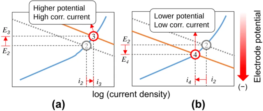
When the access of rebar to oxygen increases by cracking the concrete cover or when the passive area increases, equilibrium potential (potential in cathode at zero current) increases and the cathodic curve moves toward higher current densities. The new intersection results to a higher current but at a more positive corrosion potential, i.e. point 3 in Fig. 2-8(a). This situation is not addressed in ASTM C-876. In addition, if the cathodic current shifts to lower current densities when concentration of oxygen decreases or the passive areas are reduced, icorr decreases and the intersection, i.e. point 4 in Fig. 2- 8(b), occurs at lower Ecorr which again does not obey ASTM C-876. It is for this reason that Ecorr and icorr does not have direct correspondence, and only the risk or probability of corrosion can be elucidated from the potential data as presented in Table 2-2. The effect of oxygen and crack in concrete must be, therefore, taken into account when evaluating the corrosion behavior of reinforced concrete using half-cell potential. Despite these shortcomings, the potential method is still most widely used as non-destructive means to assess the conditions of reinforced concrete structures because of its simplicity.
Figure 2-8. Anodic and cathodic polarization curves of actively corroding steel in (a) cracked concrete and (b) in concrete with limited access to oxygen (Figures adapted from Poursaee & Hansson 15).
`
Furthermore, corrosion current density is the result of dividing the current by corroding surface. This assumes that the corrosion occurs uniformly over the exposed surface (S) just like in gravimetric analysis. According to Zou and co-workers 19, polarization measurement (Eq. 2.15) is usually accompanied by other electrochemical reactions leading to anomalous increase of corrosion rate specially during the latter stage of corrosion when rust has sufficiently formed on steel surface. It is for this reason that
Electrode potential
log (current density)
(b) (a)
(−) 2
E4 E2
i2 Lower potential Low corr. current
i4 4 2
E3 E2
i2
Higher potential High corr. current
i3 3
23
the latter method is preferentially employed when dealing with simple, comparative studies, and long-term behavior of corrosion in reinforcements.
2.2.4. Factors affecting the corrosion potential
There are three major factors that are known to influence the potential reading at concrete surface and the possibility of detecting small corrosion attack: moisture content (humidity), concrete resistivity, and depth of cover 20.
(a) Moisture content
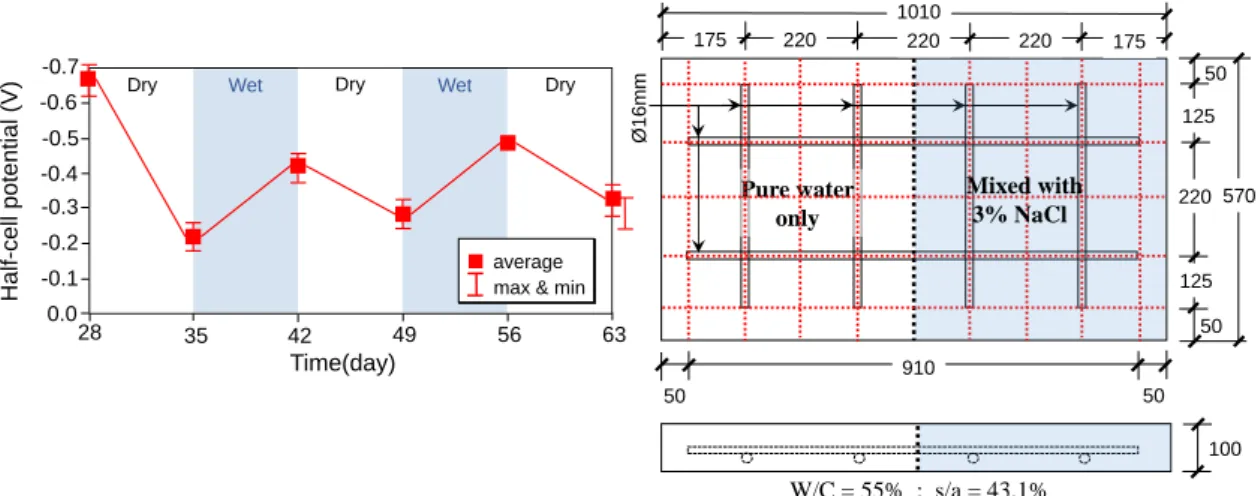
The influence of moisture on half-cell potential is illustrated in Fig. 2-9. The concentration of oxygen near at steel surface is restricted by its solubility in water. With increasing moisture content, the equilibrium potential of oxygen reduction will drop, shifting the whole potential field to more negative values, while it moves to higher values when the portion undergoes water loss during drying. This mechanism is perfectly illustrated in Fig. 2-9(a) based from the study of Leelalerkiet et al.21 derived from reinforced concrete slab as shown in Fig. 2-9(b).
Figure 2-9. Potential behavior of RC slab in wetting and drying condition. 21
(b) Concrete resistivity
Because corrosion is a flow of electric current in the form of charged ions, the resistivity of concrete will have an important influence on the amount of such current through its water-filled pores. Therefore, any modification to concrete that will improve its pore volume (porosity) and connectivity (decreasing tortuosity) will decrease the resistivity 6,17. Reducing the degree of saturation of the pores will also decrease the resistivity because transport of ion happens only when dissolved in pore water 6. Low
28 35 42 49 56 63
-0.1 0.0
Dry
-0.2 -0.5
Half-cell potential (V)
Time(day) Dry
Wet Wet Dry
-0.3 -0.4 -0.6 -0.7
average max & min
910 50
100 50 1010
175
50
50 125
220
125
220 220 220 175
Pure water only
570
Ø16mm
W/C = 55% ; s/a = 43.1%
Mixed with 3% NaCl
24
resistivity values are also measured in areas with higher chloride concentration, due to the fact that chloride are transported more easily into concrete with more open and connected pore structure 22. Under the said conditions, the rebars are depassivated and thus, active potentials usually coincide with lower resistivity. Sadowski 23 related the half-cell potential with resistivity measured from chloride-induced corrosion, and reported an appreciable increase of potential with increasing electrolyte resistivity (Fig.
2-10). The change of potentials to higher values are more pronounced in portions with low resistivities, which are usually characterized by high moisture (i.e. humid) and chloride content.
Figure 2-10. Relationship between potential and resistivity in corroded reinforced concrete slab after 90 days of 2-hour NaCl spraying followed by 20-hour drying. 23
(c) Cover depth
The potential measured over the active and passive areas becomes practically similar as cover thickness increases (Fig. 2-11). This is again due to the fact that concrete offers longer, tortuous path for charged ions to move so that the potential disturbance vanishes with increasing distance from the rebar surface. Therefore, only a shorter distance is polarized by the active area as cover thickness increases. The implication of this observation is that, potential measured over a small surface area may be considered a representative of a corroding spot using a thinner concrete cover, which can help clarify whether the rebar below the surface under study is in a state of corrosion.
Corroding area
3 4 5 6 7
-300
-400 -200 -50
Potential (mV vs. SCE)
Concrete resistivity (kΩ∙cm) -100
-150
-250
-350
-450 -500
8 9 10
0
25
Figure 2-11. Potential profile measured along a rebar model with mild steel as the central anode and 12 segmented stainless steels as cathodes. Cover depth is changed by placing the electrode in distilled water at different heights from the rebar surface. 20
2.3. Rebar passivation by concrete
Concrete has two fundamental properties that are responsible for extending the time during which transporting substances do not cause appreciable loss of metal and expansion of rust products, namely, alkalinity, and low penetrability, as explained below.
2.3.1. Alkalinity
The anodic reaction in a corroding metal does not only take a single form. If for example, a metal is put in water under controlled pH containing its own ions with varying concentration, then a series of anodic reactions exists from which the possible products of dissolution can be derived. Determining such equilibrium equations has been demonstrated experimentally 24,25. By constructing the Nernst equation of the said reactions, regions for which an element can exist as ions, solid oxides or hydroxides – as a result of producing electrons – become ultimately a function of pH and solution
Potential (mV vs. SCE)
Distance (cm)
-15 -10 -5 0 5
-400 -500 -100 -200 -250
-600
-700 10 15
0
cathode anode cathode
0.5 mm 10 mm 20 mm
Distilled water
25 25 25 25 25 25
2
25 25 25 25 25 25
2 2 2 2 10 2 2 2 2 2
20
V
Epoxy resin
Stainless
steel Mild
steel
Line of measurement
26
potential. These diagrams are collectively called Pourbaix Diagram. Examples of such diagrams for iron 14 and nickel 25 are given in Fig. 2-12.
Figure 2-12. Pourbaix diagrams of Fe (a) and Ni (b) showing possible products of dissolution based on pH and electrochemical potential. The diagrams illustrate the requirement of immunity where metal is stable (white areas); passivation where corrosion is limited (blue and orange); and where active corrosion occurs (grey).
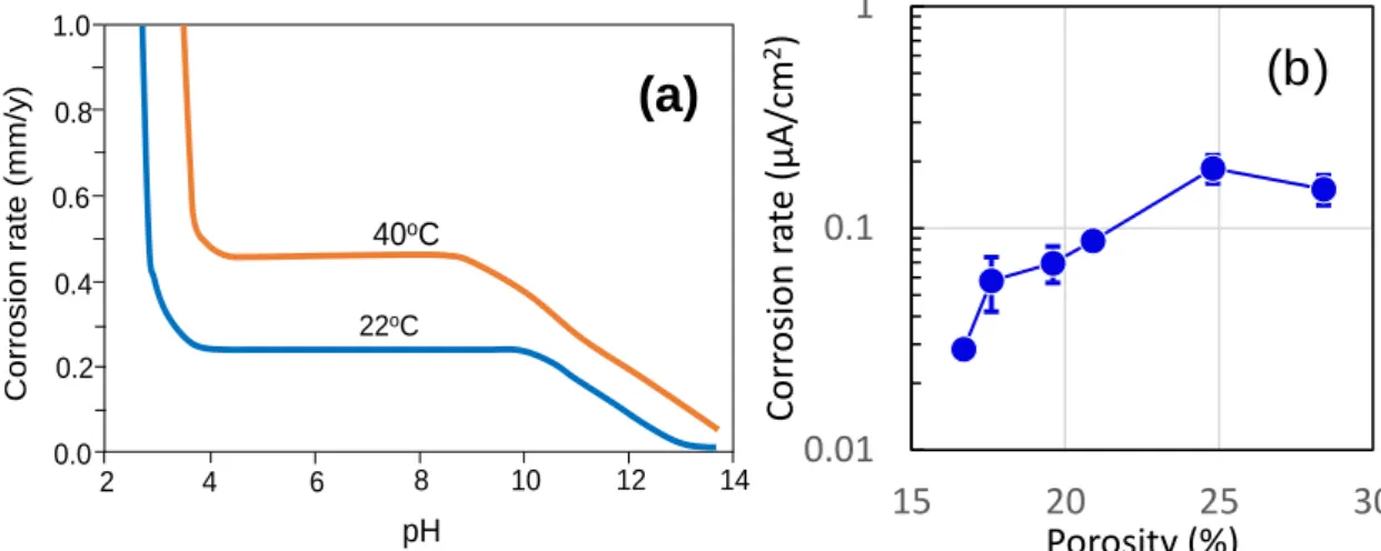
It is observed from above figures that in pore water of high pH (> 11.5), anodic reaction of metals favors solid products. In iron, the indicated phases (Fe3O4 or Fe2O3) reinforce the passive film, or by themselves act as a passivating film 26. Published data 27 presented in Fig. 2-13(a) have shown that pH at this range linearly slows down the corrosion attack on steel. In contrast, over a broad range of potential well below neutrality, the only possible products for both Fe and Ni are dissolved ions which can separate from the bulk metal and precipitate into corrosion products. As a result, corrosion proceeds at an overwhelming rate even in the presence of small oxygen concentration (Fig. 2-13(a)). This mechanisms outlines why concrete alkalinity plays a significant role in inhibiting the dissolution of metals in reinforced concrete, thus reducing the loss of metal mass due to corrosion accordingly.
2.3.2. Resistance to fluid intrusion
The durability of concrete is largely attributed to its resistance to penetrating fluids, both liquids and gas, through its mass. Concrete impermeability comes from the process of hydration products displacing the space previously occupied by water through cement hydration. According to the cathodic reaction in Eq. 2.6, oxygen together with moisture is what ultimately fuels the process forming expansive rust phases. Thus,
NiO NiOOH Ni2+
NiO2
Ni
0 2 4 6 8 10 12 14 16
-2.0 0
-1.0
-2 1.0 2.0 3.0
pH Fe2O3
Fe Fe3+
Fe2+
HFeO–2
0 2 4 6 8 10 12 14 16
0.0
-2 -1.5 0.5
-0.5 -1.0
-2 1.0 1.5 2.0
pH
Potential (V vs. SHE)
Fe3O4