INVITED PAPER
Special Section on Multiple-Valued Logic and VLSI ComputingA Survey of Intelligent Computing in Medical and Health Care System
Yutaka HATA†a),Member andHiroshi NAKAJIMA††,Nonmember
SUMMARY This paper gives a survey of intelligent computational techniques in medical and health care system. First, we briefly describe diagnosable techniques in medical image processing. Next, we demon- strate two ultrasonic surgery support systems for orthopedic and rectum cancer surgeons. In them, intelligent computational technique plays a pri- mary role. Third, computational techniques are introduced in human health care system. Usually, this goal is not to apply clinical treatment but to home use to pay consciousness to health. In it, a simple ECG and respiration me- ter are introduced with a mat sheet which detects heart rate and respiration.
Finally, a medical big data application is introduced, that is, body weight prediction is shown based on autoregressive model. Thus, we show that in- telligent computing is effective and essential in modern medical and health care system.
key words: medical imaging, health care, surgery support, soft computing
1. Introduction
Intelligent Computing techniques in medical science have been receives much considerable attention, e.g., [1], [2]. A lot of studies have been done by world-wide researchers, thereby, they made many excellent and useful computa- tional techniques in Magnetic Resonance Imaging (MRI), X-ray Computed Tomography (CT), Magnetoencephalog- raphy, and Positron Emission Transmission (PET) scanners as well as ultrasonic, infrared spectroscopy systems. Es- pecially, fuzzy c-means algorithm is now standard in func- tional MRI analysis. Surgery support systems [3], [4] are a hope to use high potential Japanese robotics techniques. On the other side, according to the increment of life style dis- ease and being super aging society in the developed coun- tries, human health care [5] is now one of the hottest tropics in the world. Health care system aims to preserve human health, especially, for preventing life style disease such as metabolic or locomotive syndrome. OMRON Corporation captures health data such as weight, height, bold pressure and body temperature. In it, the obtained data build huge volume, i.e., what we call, big data. Big data is a key word in not only health but also medical topics. Currently, various health care systems have been provided to users via Internet such as Wellness link developed by OMRON Corporation, Japan.
This paper surveys intelligent computing techniques in Manuscript received November 19, 2013.
Manuscript revised April 4, 2014.
†The author is with the Graduate School of Simulation Studies, University of Hyogo, Kobe-shi, 650–0047 Japan.
††The author is with OMRON Corporation, Kizugawa-shi, 619–
0283 Japan.
a) E-mail: [email protected] DOI: 10.1587/transinf.2013LOP0005
medical and health care systems. First, we briefly describe medical image processing studies [6]–[10]. Second, we de- scribe computational techniques based on fuzzy logic of three ultrasonic surgery support systems. One is orthope- dic surgery support system which visualizes the metal bone in human bone with an array probe of 1.0 MHz [11], [12].
Next one is a surgery support system which measures the thickness of a large intestine by a new system with five sin- gle probes of 15.0 MHz [13]. Thirdly, a human health care system is introduced, which monitors humans for 24 hours.
In night time, a bed sensor [14], [15] detects the heart rate, respiration, and the sudden change. In day time, a ther- mopile sensor detects human moving trajectory and the sud- den change [16]. Fourth one is prediction of body weight change based on autoregression model [17], [18]. Finally, we consider a future direction with respect to computational medical and health systems.
2. Medical Image Processing
Primary processes of medical image processing are segmen- tation, registration and enhancement. Image segmentation detects the region of interest (ROI) for medical diagnosis.
The segmented region helps physicians to diagnose various diseases such as volumetric and shape abnormality. For ex- ample, Alzheimer’s disease diagnosis system was developed on three-dimensional MR brain image segmentation proce- dure [6], [7]. Image registration is the process of determin- ing correspondence between all points in two images of the same scene. This helps to understand state of the ROI and plan and do surgeries. For example, image registration sys- tem between skull image obtained by an X-ray CT scanner and blood vessel image obtained by an MRI was developed for blood vessel surgery [8], [9]. Image enhancement is the process to clearly visualize the ROI. This helps physicians to observe the details of the ROI overlapped or hidden by the other portions [10]. In them, fuzzy logic provided a power- ful framework adapted to these processing as follows.
1. Fuzzy logic provides a way to represent and manipulate imprecise and uncertain information in the medical images.
2. It will be able to demonstrate knowledge of medical ex- perts.
3. It is well adapted to image processing since the natural spatial interpretation of fuzzy logic leads to efficient repre- sentations of imprecise or implicit structures in the images.
A fusion of pattern recognition and fuzzy logic leads to successful tasks to many medical applications. Still now, Copyright c2014 The Institute of Electronics, Information and Communication Engineers
medical image processing mentioned above is one of the hottest topics in medical research area [2]. They continue to require in various scene of clinical practice.
3. Ultrasonic Surgery Support System
3.1 Orthopedic Surgery Support System
In femur fracture surgery, the intramedullary nail is used as an implant for medical treatment of fractured segment (see Fig. 1). The intramedullary nail is an implant which is used in fracture surgery. It is made from metal and has no ill ef- fects on the human body. The length of intramedullary nail is approximately 250-350 mm. The intramedullary nail is vital to reinforce the fracture region of the human femur.
The intramedullary nail fixes the bone by inserting screws through the screw holes of the intramedullary nail in the bone. It is impossible to find screw holes by the naked eye because screw holes are in the bone.
Therefore, a visualization system of the intramedullary nail in the femur is needed. An X-ray device is commonly used for visualizing and locating screw holes in this femur fracture surgery. However, X-ray exposure has a serious problem for both the surgeons and patients. Therefore, non- invasive system for the human body is needed. We introduce an ultrasonography system [11], [12] which can locate screw holes of the intramedullary nail by one-direction manual scanning using the ultrasonic array probe, which is shown in Fig. 2. The array probe consists of 32 single probes (1 MHz) in line. Therefore, the array probe can obtain multiple line data at a time, and it has wide scanning range in comparison
Fig. 1 The nail and its results: left: before and right: after).
Fig. 2 The ultrasonic system and scanning.
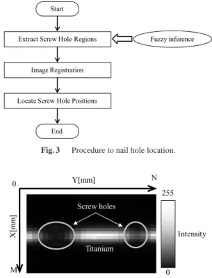
with a single ultrasonic probe. We located screw holes by the procedure consisting of three steps as shown in Fig. 3.
First one is extraction of screw hole region. We extract the regions of screw hole using fuzzy inference for the feature value map. The amplitude of reflection waves are detected from the intramedullary nail by our system. The Peak-to- Peak (P-P) value is calculated by Eq. (1).
PP=Vmax−Vmin (1)
The notation Vmax denotes the maximum amplitude of the reflection wave, and theVmindenotes the min amplitude of the reflection wave. This process is applied for all the ob- tained ultrasonic waveforms. All PPvalues are converted into intensities from 0 to 1 by Eq. (2).
Intensity= PP−PPmin PPmax−PPmin
(2) The notationPPmax denotes the maximum value ofPPval- ues, and thePPmin denotes the minimum value ofPPval- ues. Figure 4 shows an example of the feature value map.
In this map, the brighter pixel indicates the larger echoes from the intramedullary nail, and dark pixel indicates screw hole and the background regions. We determine the long axis direction of the intramedullary nail, as shown in Fig. 5.
The center of gravity of the intramedullary nail is calculated by Eq. (3) after binarization, where, binarization threshold is manually determined. The notationmxandmydenote x- coordinate and y-coordinate of the center of gravity point in the image f(x,y), respectively. The notation M andN denote height and width size of the feature value map, re- spectively.
Fig. 3 Procedure to nail hole location.
Fig. 4 Feature value map.
Fig. 5 Long axis direction.
Fig. 6 Fuzzy membership functions.
[mx,my]=
⎡⎢⎢⎢⎢⎢
⎢⎢⎢⎢⎢
⎢⎢⎢⎢⎢
⎢⎢⎢⎢⎢
⎢⎣
M x=1
N y=1
x×f(x,y) M
x=1
N y=1
f(x,y) ,
M x=1
N y=1
y×f(x,y) M
x=1
N y=1
f(x,y)
⎤⎥⎥⎥⎥⎥
⎥⎥⎥⎥⎥
⎥⎥⎥⎥⎥
⎥⎥⎥⎥⎥
⎥⎦
(3)
The gradientgof the nail is calculated by Eq. (4).
g= M x=1
N y=1
(x−mx)×(y−my)×f(x,y) M
x=1
N y=1
(x−mx)2×f(x,y)
(4)
Next, we extract screw hole regions of the intramedullary nail using fuzzy inference. Knowledge 1 and Knowledge 2 are considered.
Knowledge 1:Average of the intensity is low on the screw hole region.
Knowledge 2:Variance of the intensity is high on the axis of the intramedullary nail.
From these, fuzzy IF-THEN rules are derived below.
Rule 1: IF Average of the intensity xa is low, THEN the degreeµaveis High.
Rule 2: IFVarianceof the intensity xvis high, THEN the degreeµvaris High.
These fuzzy IF-THEN rules are represented by the fuzzy membership functions LOW and HIGH, which are defined in Fig. 6. The notation xa(x,y) denotes the aver- age of eight neighborhood pixels of (x,y) in the feature value map. The notation xv(x,y) denotes the variance of the intensity along the long axis of the intramedullary nail.
The notationsmaxaandmaxvdenote the maximum value of
Fig. 7 Obtained image.
Fig. 8 Model image of the nail (truth image).
Fig. 9 Extracting screw holes from the truth image.
xa(x,y) andxv(x,y), respectively. The fuzzy singleton func- tionSxa(x,y)(u) is defined by Eq. (5), whereuis the variable in the domain.
Sxa(x,y)(u)= 1 if u=xa(x,y)
0 if uxa(x,y) (5)
TheSxv(x,y)(v) is defined in the same way. A gray scale im- ageU(x,y) is derived by Eq. (6).
U(x,y)=255×min(Sxa(x,y)(u),LOW)
×min(Sxv(x,y)(v),HIGH) (6) Here, the fuzzy calculation achieved robustness for chang- ing the intensity range of the input image by employing these fuzzy membership functions with dynamic parameters ofmaxaandmaxv.
Second procedure is the image registration. We first move the center of gravity coordinate of the intramedullary nail of the U(x,y) (Fig. 7) to upper left of the model im- age M(x,y). The model image (Fig. 9) is obtained from a camera image (Fig. 8). A translation process is repeated un- til the center of gravity coordinate is scanning to the lower right, i.e., all area. While performing this Euclidean Trans- lation, we calculate square sum of difference,Diff, between the obtained image and the model image by Eq. (7).
Diff = M
x=1
N y=1
U(x,y)−M(x,y)2
(7) This process performs with a few seconds of processing time
Fig. 10 Registration between the nail picture and ultrasonic image.
Fig. 11 Locating results.
Fig. 12 Measurement device based on J & J circular stapler.
because sizes of the obtained image and model image con- sists of 24×30 pixels. We choose the translation matrix with the minimalDiff. Then, the obtained image is translated to the determined position. The image is shown in Fig. 10. The required holes are located by the translation matrix as shown in Fig. 11. The experimental results are as follows. When the intramedullary nail was horizontal, the screw holes were located within the mean error of 1.7 mm in every scanning interval of 1.0, 1.5, 2.0, 2.5 and 3.0mm. When the nail was not horizontal, the holes were located within the mean error of 1.8 mm in the every scanning interval.
3.2 Rectum Cancer Surgery Support System [13]
Low anterior resection is one of the operative methods for rectum cancer. In this method, surgeon excises the lesion department with laparotomy, and surgeon anastomoses in- testinal tracts in the rectum part near the anus. An anas- tomosis is to sew up between intestinal tracts after lesion department excision. A device which joins two tubular or- gans was developed by J & J. This device is called a circu- lar stapler shown in Fig. 12. Using the circular stapler, sur- geon can easily anastomose between intestinal tracts in the narrow pelvis, and preservation of an anus is enabled. The circular stapler consists of the body part and the part anvil which catches a staple. In the anastomosis used with the circular stapler, the anastomosis is performed by the staple.
1. Surgeon inserts the anvil in the intestinal tract of the one side after the excision and sews it up with a suture and fixes
Fig. 13 Five ultrasonic probes (left) and the object (right).
Fig. 14 Experiment illustration.
an anvil.
2. Surgeon sews up other intestinal tract with a suture.
Third, surgeon inserts the shaft which is the tip of the cir- cular stapler into an anus.
3. The drill penetrates the top of the intestinal tract sewed up with a suture. The drill is at the tip of the shaft.
4. Surgeon combines the drill and the anvil, and anasto- moses by a staple.
When the drill penetrates the intestine, the thickness of the intestine becomes thinner. If the intestine is strongly pulled, the corresponding cells necrotize. Then, strong pain is caused, and the worst case caused the death of the patient.
To solve this problem, it is necessary to measure the change of the thickness of the intestine when the drill penetrates the intestine. It is necessary to recognize the change of the thickness of the intestine in the surgery. We describe a thick- ness determination method of the intestine with the ultra- sonic probe of 15 MHz. Figure 13 shows the developed five probes stapler. Figure 14 shows an illustration of the exper- iment. The thick determination method employed the fuzzy inference scheme. The method consists of three steps. First, we determine the surface point of the object from the acqui- sition waveform. Second, we determine the bottom point of the object by using a fuzzy inference. The fuzzy inference is made by employing amplitude, correlation, and estimated thickness fuzzy membership functions. In the functions, we express the knowledge of ultrasonic wave on target object in the similar way to Sect. 3.1. Finally, we calculate ob- ject thickness from the surface point, the bottom point and the acoustic velocity of the object. As the result, we have measured the object thickness within the mean error rate of 6.11%.
4. Home Care System for Aging People
Figure 15 shows a home care system with two sensors. A mat sensor detects heart beat and respiration in night, and a thermopile sensor detects the human state in day time. Both sensors never disclose the privacy and provide no intrusion to the users.
4.1 Heart Rate and Respiration Detection
Figure 16 shows the mat sensor system [14]. The mat sen- sor system consists of the air tube in cushion of 175mm× 780mm and an ultrasensitive pneumatic sensor (Fujicera, FKS-111). This sensor detects a pressure change generated by the power provided to the tubes. It outputs electronic signal based on 1.35 Volt. This signal is quantized to 1024 levels by the A/D converter with the control device. The ob- tained data is provided to the personal computer via wireless network.
The mat sensor is set under of the bottom of a mattress.
The vibration of the body of the patient is directly detected by the mat sensor.
<Fuzzy Algorithm>
Generally, biosignal has a cycle and revealed as a peak in biosignal waves. Heart wave is usually very regular and is not controlled by our will. Respiration is also regular in nor- mal condition and is controlled by our will. By using these properties, we propose a detection algorithm for biosignal points in the framework of fuzzy logic. From the above con- sideration, we can obtain the following knowledge.
Knowledge 1: A large peak is the biosignal peak.
Knowledge 2: The biosignal has no sudden change, it has a cycle.
We explain a fuzzy detection algorithm on the basis of
Fig. 15 Two sensor system without any intrusion.
Fig. 16 Mat sensor system with air pressure sensor.
the above knowledge.
<Fuzzy biosignal detection algorithm>
For an input biosignal valuext, (t: time). The notation hi(i = 1,2, . . . ,n) denotes the biosignal peak point (target point).
Step 0: Seti=1, we determine the point of the first highest peak point ash1.
Step 1: Fori←i+1, we define two fuzzy membership func- tions: one extracts the amplitude peak based on Knowledge 1 and the other extracts the period based on Knowledge 2.
First, we derive the following fuzzy rules, where the nota- tions µAmp(xt) and µInt(xt) denotes the fuzzy degrees with respect to the amplitude and interval, respectively.
Rule 1: IFa(xt) is HIGH, THEN the fuzzy degree of the bio-signal point,µAmp(xt), is high.
Rule 2: IFtis CLOSE to the cycleTj, THEN the fuzzy degree of bio-signal point,µInt(xt), is high.
The fuzzy membership functions HIGH and CLOSE are defined in Fig. 17. In this figure, the notation Tj de- notes a cycle of the biosignal. The notationsmin andmax are dynamic parameters which are calculated as the mini- mum and maximum values in the range betweent(hi−1) and t(hi−1)+2×Tj[sec], respectively. The notationt(hi) denotes the time athi. TheµInt(xt) is calculated by “CLOSE” mem- bership function by Eq. (8) in the time range of t(hi−1)≤t≤ t(hi−1)+2×Tj[sec].
µInt(xt)=CLOSE(t−t(hi−1))
=exp
⎛⎜⎜⎜⎜⎜
⎝−(t−t(hi−1)−Tj)2 2(Tj/3)2
⎞⎟⎟⎟⎟⎟
⎠ (8)
Fuzzy singleton functionssa(xt) is defined by Eq. (9).
sa(xt)= 1 if xt=a
0 otherwise (9)
Fig. 17 Fuzzy membership functions for detecting heart signal.
Fig. 18 The thermopile array sensor.
Fig. 19 Trajectory recording.
The fuzzy degreesµAmp(xt) is calculated by Eq. (10).
µAmp(xt)=min(HIGH,sa(a(xt))) (10) The total degreeµTotal(xt) of the heartbeat point is calculated by the algebraic product by Eq. (11).
µT(xt)=µAmp(xt)×µInt(xt) (11)
We determine the bio-signal pointhi as the point with the maximumµT(xt).
Step 2: Ifin, goto Step 1, and ifi=n, stop.
We detect the heartbeat and respiration signal based on this fuzzy algorithm. The heartbeat was detected at 0.894±0.083 of correlation coefficient on five minute each of ten subjects, where we used the moving average of the previous3 datum points asTj. The respiration count was detected at 3.1±1.56 of mean absolute error. Thus, the mat sensor detects heart rate variability and respiration with high accuracy. In addition, we detected apnea period in sleeping by applying Fourier transform to the biosignal [15].
4.2 Human Movement Detection
Figure 18 shows the thermopile sensor used here. The sen- sor detects the human by using the distribution. Figure 19 shows the example of our system results. Right figures shows the data of the array sensor and the left figures shows the trajectory of human moving. The sensor system detected human area based on fuzzy inference and detected adjoined people from its label size. The system successfully esti- mated the human moving trajectory. Figure 20 illustrated an example of trajectory map. Physician can judge the demen- tia of the person by analyzing the trajectory. The technical details are shown in Ref. [16].
Fig. 20 Trajectory map.
5. Prediction of Weight for Health Management Health management system is also the hottest topics in medicine and heath care because the life style diseases have become big problem. Methods which predict future trend or know risk to come down with lifestyle diseases are nec- essary for health management system. We proposed au- toregressive (AR) model [17] and Vector AR model to pre- dict bodyweight of next one day [18]. The AR model was fixed based on body weight data. On the other hand, the VAR model was fixed by body weight data and biologi- cal data which are obtained by pedometer. Parameters in these models were calculated by Yule-Walker equation and Akaike’s Information criterion. As the results for 452 sub- jects, the correlation coefficients of the AR model and the VAR model obtained 0.784±0.174 and 0.831±0.164, re- spectively. The mean absolute prediction errors of the AR model and the VAR model obtained 0.38 kg (0.58%) and 0.40 kg (0.60%), respectively. Next, we proposed Fuzzy-AR model and Fuzzy prediction model to predict body weight change for next plural days. We employed fuzzy member- ship function for fixing these models. The Fuzzy-AR model was fixed based on body weight data. In the Fuzzy-AR model, we made a fuzzy membership function based on the order of the AR model. The Fuzzy prediction model was constructed by an AR model based on body weight data and four linear prediction models based on the biological data.
The fuzzy membership function controls the magnitudes of biological data added to AR model. As the result of apply- ing prediction models for the same subjects, the correlation coefficients of the AR model and Fuzzy-AR model obtained 0.298±0.273 and 0.741±0.205, respectively. The absolute prediction errors of AR model and the Fuzzy-AR model ob- tained 1.43 kg (2.07%) and 0.48 kg (0.71%), respectively.
Thus, we predicted the body weights from their past data.
6. Conclusion
This paper summarized medical image processing, surgery support and health monitoring techniques. In general, medi- cal imaging and surgery support system were developed for special needs of the physician. They help both physician and patients although the applicable markets are small. In the
future, we should develop a total medical and health care in- telligent system for both physicians and patients. Then, we must consider the followings:
(1) Future diagnosis needs multi-modality images of MR, X-ray MDCT, PET, and so on. It needs system of systems engineering for sensor device, hardware and software for diagnostic imaging. Then, intelligent computing techniques are needed to improve the diagnostic quality.
(2) Medical image scanners provide huge image data ac- cording to the development of computer hardware and soft- ware. It is no time for radiologists to diagnose every image slices. Therefore, automated diagnosis tool is strongly re- quired for them. Fuzzy model representing the radiologist and medical knowledge gives a powerful tool to develop this system.
(3) According to rapid advance of new human health care service, the computer system requires faster data processing in the big data. Prediction, detecting abnormality, and find- ing of valued features would play the primary role in big data. Cloud computing gathers the data and achieves real time data processing.
(4) New sensing technology with low-invasive and high sensitive devices will be employed for health management.
Then, new wearable biosignal sensing system becomes pop- ular. The old fashion one would be giving way to this new measurement system. For example, wearable influenza de- tection system would be made by measuring boy tempera- ture, respiration and sound of breast in the near future. Then, it would replace current diagnosis method. On these newly developed wearable systems, wireless secure communica- tion tool with low power and high reliability required.
A total medical and health care system needs new intel- ligent computing to improve the quality and quantity. Soft computing approaches with knowledge and mind of physi- cian, patients and healthy people must be used for future medical and health care system with more reliable and safer technology.
Acknowledgements
This research was supported in part by JSPS KAKENHI Grant-in-Aid for Scientific Research (A) (Grant number 25240038).
References
[1] Radiology, RSNA, USA.
[2] Trans. on Medical Imaging, IEEE, USA.
[3] Journal of Orthopedic research, ORS, USA.
[4] Surgery, Elsevier, Holland.
[5] http://www.continuaalliance.org/.
[6] H. Kitagaki, E. Mori, S. Yamaji, K. Ishii, N. Hirono, S. Kobashi, and Y. Hata, “Frontotemporal dementia and Alzheimer disease: evalua- tion of cortical atrophy with automated hemispheric surface display generated with MR images,” Radiology, vol.208. no.2, pp.431–439, Aug. 1998.
[7] Y. Hata, S. Kobashi, S. Hirano, H. Kitagaki, and E. Mori, “Auto- mated segmentation of human brain MR images aided by fuzzy in- formation granulation and fuzzy inference,” IEEE Trans. Syst. Man
Cybern. C, vol.30, no.3, pp.381–395, Aug. 2000.
[8] S. Kobashi, Y. Hata, M. Ishikawa, Y. Kitamura, and T. Yanagida,
“Medical image registration based on fuzzy and multiple-valued log- ics,” Proc. Second Int. Forum on Multimedia and Image Processing, pp.270–275, May 2000.
[9] Y. Hata, S. Kobashi, N. Kamiura, Y. Kitamura, and T. Yanagida,
“On the architecture of medical image registration system based on multiple-valued logic,” Proc. IEEE Int. Symp. on Multiple-Valued logic, pp.273–278, May 2000.
[10] S. Kobashi, K. Kondo, and Y. Hata, “Target image enhancement us- ing representative line in MR cholangiography images,” Int. J. Imag- ing Systems and Technology, vol.14, no.3, pp.122–130, 2004.
[11] M. Endo, K. Nagamune, N. Shibanuma, S. Kobashi, K. Kondo, and Y. Hata, “An ultrasonography system aided by fuzzy logic for identi- fying implant position in bone,” IEICE Trans. Inf. & Syst., vol.E90- D, no.12, pp.1990–1997, Dec. 2007.
[12] Y. Ikeda, S. Kobashi, K. Kondo, and Y. Hata, “Fuzzy ultrasonic array system for locating screw holes of intramedullary nail,” Proc. 2007 IEEE Int. Conf. on Systems, Man and Cybernetics, pp.3428–3432, 2007.
[13] G. Hiramatsu, S. Kobashi, Y. Hata, and S. Imawaki, “Ultrasonic large intestine thickness determination system for low anterior resec- tion,” Proc. 2008 IEEE Int. Conf. on Systems, Man and Cybernetics, pp.3072–3076, 2008.
[14] Y. Hata, S. Kobashi, K. Kuramoto, and H. Nakajima, “Fuzzy biosig- nal detection algorithm and its application to health monitoring,” Int.
J. Applied and Computational Mathematics, vol.10, no.1, pp.133–
145, 2011.
[15] K. Ho, N. Tsuchiya, H. Nakajima, K. Kuramoto, S. Kobashi, and Y.
Hata, “Data synthesis for heartbeat detection system of two sensor systems,” Proc. 2010 International Symposium on Intelligent Sys- tems, 2010.
[16] M. Kuki, H. Nakajima, N. Tsuchiya, and Y. Hata, “Human move- ment trajectory recording for home alone by thermopile array sen- sor,” Proc. 2012 IEEE Int. Conf. on Systems, Man and Cybernetics, pp.2042–2047, 2012.
[17] H. Tanii, H. Nakajima, N. Tsuchiya, K. Kuramoto, S. Kobashi, and Y. Hata, “A fuzzy-AR model to predict human body weights,”
Proc. 2012 IEEE World Congress on Computational Intelligence, pp.2027–2032, 2012.
[18] H. Tanii, H. Nakajima, N. Tsuchiya, K. Kuramoto, S. Kobashi, and Y. Hata, “A fuzzy time-series prediction model with multi-biological data for health management,” Proc. 6th International Conference on Soft Computing and Intelligent Systems and 13th International Sym- posium on Advanced Intelligent Systems, pp.1265–1268, 2012.
Yutaka Hata received the B.E. degree in 1984, the M.E. degree in 1986 and the Ph.D.
in 1989 all from Himeji Institute of Technol- ogy, Japan. He is currently a Professor in the Graduate School of Simulation Studies, Uni- versity of Hyogo, Japan. He spent one year in BISC Group, University of California at Berkeley from 1995 to 1996 as a visiting scholar. His research interests are in medical system, health monitoring system, fuzzy system and Immune system. He received 13 interna- tional awards such as the Franklin V. Taylor Best Paper Award (IEEE SMC 2009), etc. He is an Editor-in-chief of International Journal of Intelligent Computing in Medical Sciences and Image Processing, USA and 5 Jour- nal editors including IEEE Systems Journal. He is an IEEE Fellow and an IEEE SMCS BoG member.
Hiroshi Nakajima received the B.E. de- gree in 1985 from Kobe University and Ph.D in 2004 from Kumamoto University. He is an Advisory Technology Specialist at the Technol- ogy and Intellectual Property H.Q. of OMRON Corporation, Kyoto, Japan. His interests include human-machine collaborative systems with op- timal integration of human and machine intelli- gence based on fuzzy logic and soft computing.
He is also interested in health management tech- nologies for humans, machines, and nature. He received the Industrial Outstanding Application Award from International Fuzzy Systems Association in 2007, the best paper award from Japan Soci- ety for Fuzzy Theory and Intelligent Informatics in 2009, and Biomedical Wellness Award from SPIE in 2011.