Japan Advanced Institute of Science and Technology
Title
Combining-after-Decoding Turbo Hybrid ARQ by
Utilizing Doped-Accumulator
Author(s)
Ade Irawan; Anwar, Khoirul; Matsumoto, Tad
Citation
IEEE Communications Letters
Issue Date
2013-05-13
Type
Journal Article
Text version
author
URL
http://hdl.handle.net/10119/11214
Rights
This is the author's version of the work.
Copyright (C) 2013 IEEE. IEEE Communications
Letters, 2013,
DOI:10.1109/LCOMM.2013.043013.130059. Personal
use of this material is permitted. Permission
from IEEE must be obtained for all other uses, in
any current or future media, including
reprinting/republishing this material for
advertising or promotional purposes, creating new
collective works, for resale or redistribution to
servers or lists, or reuse of any copyrighted
component of this work in other works.
Description
Author's version of the paper will be archived
here after the publication.
different doping rates per transmission phases for hybrid auto-matic repeat request (ARQ). Horizontal iteration (HI) performed for decoding the serially concatenated codes (SCC) is followed by Vertical iteration (VI) to exchange extrinsic log-likelihood ratio (LLR) of the uncoded (systematic) bits, and the HI/VI chain is repeated. The doped-accumulator enables the two extrinsic information transfer (EXIT) curves of the SCC to match very well and the convergence tunnel to open until a point very close to the (1.0,1.0) mutual information point. Excellent performance of our technique is verified through EXIT analysis as well as frame-error-rate (FER) and throughput simulations.
Index Terms—Hybrid ARQ, turbo principle,
doped-accumulator.
I. INTRODUCTION
E
XCHANGING soft information in an iterative (turbo) fashion for packet combining in automatic repeat request (ARQ) systems has been intensively investigated in the last few years. Reference [1] first introduced the utilization of the Turbo encoder structure in hybrid ARQ (HARQ). The HARQ system forms parallel concatenation of multiple recur-sive convolutional codes, which is corresponding to multiple transmissions of the same information, if random interleaving is performed in the parallel branches of the encoder. At the receiver side, the packet combining-after-decoding (CAD)1 isperformed to exploit the soft information expressed in the form of a priori log-likelihood ratio (LLR) of the uncoded (systematic) bits obtained in the last transmission for decoding the current transmission. It is shown in [1] that a considerable frame-error-rate (FER) performance gain can be achieved over conventional ARQ without packet combining.
The CAD concept has been adopted in various forms that can be found in the literatures. Reference [2] exploits the structure of [1] with systematic recursive convolutional code as the encoder instead of turbo code. In the technique shown in [2], only either systematic or parity bits are retransmitted, and hence a considerable throughput improvement can be achieved. Reference [3] considers rate compatible punctured turbo coded HARQ to provide higher throughput. A similar technique is proposed in [4], where the parity spreading
A. Irawan and K. Anwar are with the School of Information Science, Japan Advanced Institute of Science and Technology (JAIST), 1-1 Asahidai, Nomi, Ishikawa, Japan 923-1292 (e-mail: {ade.irawan, anwar-k}@jaist.ac.jp).
T. Matsumoto is with the School of Information Science, Japan Ad-vanced Institute of Science and Technology (JAIST), 1-1 Asahidai, Nomi, Ishikawa, Japan 923-1292 (e-mail: [email protected]), and the Center for Wireless Communication, University of Oulu, FI-90014 Finland (e-mail: [email protected]).
Manuscript received mm dd, yyyy; revised mm dd, yyyy.
1The terminologies "before" and "after" are relative to the channel decoder.
An alternative way to packet combining in the framework of ARQ in multipath propagation environment is combining-before-decoding (CBD). The CBD technique combines all path energies of the transmitted signals to achieve diversity gain at the receiver.2CBD can be performed by joint soft equalization
and packet combining using a maximum a posteriori (MAP) equalizer, as introduced in [6]. The algorithm is an extension of the well-known turbo equalization to a single-input multiple-output (SIMO) channel where signal samples, received in each retransmission phase, are stored and combined by the turbo equalizer; this concept is referred to as integrated equalization (IEQ) in [6]. The same idea for packet combining by using MAP equalization is also proposed in [7]. Although the MAP algorithm can achieve the optimal performance, its compu-tational complexity increases exponentially with the channel memory length. Most recently, the technique presented in [8] employs frequency domain turbo equalization with soft combining ARQ at the equalizer in a full-duplex system.
Another form of CBD is combining the interleaved LLRs of equalizers outputs, known as turbo-diversity transmit (TDT) in [5] or bit-interleaving diversity (BID) in [9]. Reference [5] introduces an improved turbo-diversity scheme to IEQ by ex-ploiting different interleaver in every retransmission to reduce the Euclidean distance dispersion. As for IEQ, retransmission of the same codeword with an identical interleaver for every retransmission achieves only a path diversity. It can easily be expected that in frequency-selective fading channels, the both CAD and CBD techniques can achieve a diversity order of multipath number k transmission(s). On the top of the diversity gain, both the techniques can achieve coding gain, where this letter shows that higher coding gain can be achieved by CAD. We show the capacities of the CAD and CBD techniques, and verify the achievability of their corresponding asymptotic performances via computer simulations. We then show that the introduction of doped-accumulator DAcc [10] – [11] with diff-erent doping rates in each transmission can improve the CAD performance while reducing the computational complexity.
The rest of this paper is organized as follows. The proposed turbo HARQ strategy is presented in Section II. Results of the extrinsic information transfer (EXIT) chart analyses provided in Section III are used to verify the simulation results presented in Section IV. Finally, Section V concludes this letter.
Fig. 1. Transmitter of doped-accumulator assisted turbo HARQ systems
II. PROPOSEDTURBOHARQWITH
DOPED-ACCUMULATOR
The transmitter of the turbo HARQ system proposed in this letter is depicted in Fig. 1. The maximum times of transmission attempts is set at K (with K − 1 retransmissions). The bit stream b0 of the first transmission attempt is encoded by
a rate R non-systematic non-recursive convolutional codes (NSNRCC) C1. The output of C1 is then interleaved by a
random interleaver Π1. The output of Π1is fed into doped
ac-cumulator DAcc with a generator G = [3,2]8. DAcc introduces
no redundancy and its decoder requires only moderate addi-tional complexity. The doped-accumulated bits are modulated by BPSK. Puncturing may be performed to achieve higher throughput as indicated in [3]. However, this paper leaves the issue of code optimization as a future study.
When the transmitter receives a positive acknowledgement (ACK), it indicates a successful decoding and thereby the transmitter moves on to the next frame transmission. If the transmitter receives a negative acknowledgement (NACK), it indicates an unsuccessful decoding at the receiver, and hence the transmitter retransmits the same information.
For the k-th attempt, k = {1, 2, · · · , K}, b0 is interleaved
every r-th retransmission r = {1, 2, · · · , k − 1 | k 6= 1}, yielding br = Πvr(b0) ,where Πvr(·) is the function
performing vertical interleaving. The transmitter transmits a vectorized signal having N symbols, as xk = [xk(1), xk(2), · · · , xk(N )]T ∈ CN ×1.
At the receiver side, the received signal yk of the k-th
transmitted frame is given by yk = Hkxk + νk ∈ CN ×1,
where νk is a zero mean complex additive white Gaussian
noise (AWGN) vector with variance σ2, corresponding to
the specified signal-to-noise power ratio (SNR). The channel is assumed to be static within a frame, and statistically independent varies frame-by-frame. The channel matrix Hk
is a Toeplitz matrix with the dimensionality (N + L − 1) × N , where L is the channel memory length. With the cyclic prefix (CP) transmission, Hk becomes an N × N circulant
matrix with the multipath channel response on its first column: [h(0), h(1), · · · , h(L − 1), 0, · · · , 0]T. Then we can utilize the characteristic of the circularity to obtain a diagonal matrix
2The combining should not necessarily be in the path energy domain, but can be in their LLR domain, as indicated in [5].
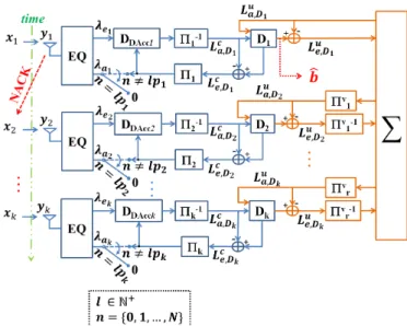
Fig. 2. Receiver of doped-accumulator assisted turbo HARQ systems
of frequency domain channel matrix Ψk = FHHkF. This
property is well utilized in the frequency-domain soft can-cellation and minimum mean squared error (FD/SC-MMSE) turbo equalization (EQ). However, since the algorithm of the FD/SC-MMSE equalization technique is already well known [12]–[14], this letter does not provide its details. The results of log-likelihood ratio (LLR) are exchanged via horizontal itera-tion (HI) between the equalizer+deaccumulator (EQ+DDAcc)
and the decoder (D). For the decoders DDAcc and D, we use
Bahl-Cocke-Jelinek-Raviv (BCJR) algorithm [15]. A. Packet Combining After Decoding
The HI takes place independently in different phases of transmission, as shown in Fig. 2. Therefore the channel matrix size stays the same for every HI. The HI is performed until no relevant improvement in mutual information (MI) is achieved, and then the obtained extrinsic LLR of the systematic infor-mation bits, Lue,D, is combined into Lus as
Lus = Lue,D1+ k X i=2 Πvi−1(Lue,Di). (1) Lu
s is fed back to soft-input soft-output (SISO) channel
de-coders as the a priori information, as depicted in Fig. 2, referred to as vertical iteration (VI). The (VI) can be seen as iterative decoding process of parallel concatenated code. Finally, by performing sufficient times of iterative HI-VI-HI-VI decoding, the final hard decision, ˆb, is made on the a posterioriLLR of the information (systematic) bits.
B. Doped-Accumulator
DAcc is composed of a memory-1 systematic recursive convolutional code with octal generator of ([3,2]38) followed
by heavy puncturing of the parity bits. Every p-th3systematic
3p without index indicates the doping rate, while p with the index k
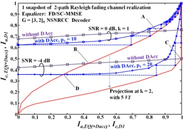
Fig. 3. EXIT chart of Equalizer (+ DDAcc) for single snapshot of channel
realization and NSNRCC decoder at k = {1,2}
bits are replaced by the parity bits. As shown in Fig. 1, DAcc is performed after the its corresponding interleaver. At the receiver, DDAcc follows the FD/SC-MMSE equalization.The
a priori LLR to the equalizer is set to zero for every p-th bit, as shown in Fig. 2. Hence, it is important to note that when p = 1, DAcc is equivalent to a full accumulator; in this case, no LLR of the accumulated bits is fed back from the channel decoder to the equalizer.
III. EXIT ANALYSIS
The structure of the CAD technique enables the use of diff-erent doping rates of the DAcc transmission-by-transmission to achieve better matching of the EXIT curves. The doping rate of the first transmission is determined by evaluating the EXIT curves of inner and outer code so that they are best matched among the all possible values of the doping rates, while keeping the convergence tunnel open. In such parameter settings, no retransmission is required if the received SNR is larger than the threshold at which the convergence tunnel opens.
Fig. 3 shows the EXIT curves of EQ and EQ + DDAcc,
with a generator [3,2]8 NSNRCC’s decoder, for a single
snapshot channel realizations at the first transmission and the same channel for retransmission.4 The figure also shows the
trajectory with the maximum iteration of 350. We set the interleaver length to 20000 bits. For k = 1, we set the doping rate p1 of DAcc assisted CAD (ACC-CAD) to 10 and the
average SNR to 0 dB. It shows that the EQ curve intersects the decoder curve at point "A", while EQ+DDAcccurve with
p1= 10 makes the convergence tunnel open until a point very
close to the (1.0,1.0) MI point.
At SNR = −4 dB, which is relatively low, the EQ curve intersects the decoder curve at point "B" whereas EQ+DDAcc
curve with the doping rate p1 = 20 at first intersects at
4The channel of the second transmission is generally different from the
first, but in this figure we assume the same because the purpose of the EXIT analysis shown in this Section is to demonstrate how the EXIT curve change by the VI.
IV. SIMULATIONRESULTS
To evaluate the performances, computer simulations has been conducted in multipath Rayleigh fading channels. Ran-domly generated binary sequence with a length of 512 infor-mation bits per frame were used as b0. Then, for ACC-CAD,
b0 and br are independently coded by the same memory-1
rate 1/2 NSNRCC encoder with generator polynomial ([3 2])8.
For comparison, we also tested memory-2 rate 1/2 NSNRCC encoder with generator polynomial ([7 5])8for both CAD and
CBD without DAcc. Here, the total memory that used at the receiver for all the evaluated systems are the same. However, both memory-1 code NSNRCC and DAcc with the proposed system, having only two states in their trellis diagram, and hence decoding complexity is lower than the other cases used for comparison.
We set 2-path independent and identically distributed (i.i.d.) block fading channel with equal average path gains. We assume that the receiver has perfect knowledge about the channel, including frame and symbol timings. We assume stop-and-wait protocol with error-free feedback channel. We also assume perfect packet error detection.
First, we evaluate the FER performances of the ACC-CAD with doping rates p1 = 10, p2 = 20, p3 = 50, and
p4 = 100. Then for comparison, we evaluate CAD without
DAcc and refer TDT in [5] as the CBD. We also evaluate the outage probability of CBD and CAD in 2-path Rayleigh fading channels via a series of Monte Carlo simulations with respect to the fading variations, based on the static capacity with the Chase combining and incremental redundancy HARQ schemes, respectively [16].5 It is found that the decay of FER
curve follows asymptotically that of the outage curve. We perform simulations with maximum retransmission to 3 (K = 4). For fair comparison, we set the maximum iteration times at 350 for every (re)transmission for all the tested systems.6 With CAD, for k = 2, we perform first one HI in
each branch then followed by five VIs; the HI and VI process are repeated 50 times, referred as activation ordering pattern 50(H1V5). The activation ordering pattern for k = 3 and k = 4 are 43(H1V5) and 38(H1V5), respectively.
For the first transmission (without combining), the both CAD and CBD systems schemes achieve the same outage
5For fair comparison, the total signal energy is normalized to per-transmission.
6The iteration is stopped when no relevant increase in the mutual
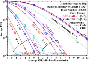
Fig. 4. FER performance
probability. In this case, the system performance is determined by the path diversity and coding gains that can be achieved by the HI only. It is found from Fig. 4 that the proposed CAD outperforms the systems without DAcc, as predicted from the EXIT analysis.7 With k > 1, the outage probability
of CAD is lower than CBD; hence it is found that CAD clearly outperforms CBD. With ACC-CAD, the gap between FER and the outage probability, at FER = 10−3 for K = 2, is 2.74 dB whereas with the CBD the gap is 4.56 dB. Similarly, for K = 4, the gap between the FER curve and the outage probability with the ACC-CAD is 2.78 dB whereas the CBD is 4.90 dB.
The excellent performance of the proposed systems is also shown in terms of throughput efficiency at relatively low SNR in Fig. 5. With the ACC-CAD technique, as the throughput curves with every K value converge at SNR around 4 dB, we only need one retransmission, when SNR > 4 dB, to achieve the highest throughput. Fig. 5 also shows that ACC-CAD with only one retransmission outperforms the CBD with three retransmissions over the SNR value range of -2 dB ≤ SNR ≤ 8 dB in average.
V. CONCLUSION
This letter has proposed CAD HARQ technique using doped-accumulator (DAcc) and vertical iteration (VI) decod-ing. It has been shown that the proposed system outperforms the HARQ systems without DAcc. With the help of EXIT chart analysis, it has been shown that a better matching between EQ + DDAccand NRNSCC decoder’s EXIT curves,
concatenated with VI decoding, can be achieved with the proposed technique, which results in excellent FER and throughput performances. The superiority of CAD over CBD has also been verified via computer simulations in multipath Rayleigh fading channels.
REFERENCES
[1] K. R. Narayanan and G. L. Stuber, “A novel ARQ technique using the turbo coding principle,” IEEE Commun. Letters, vol. 1, no. 2, pp. 49–51, March 1997.
7Result for K = 3 is not shown to simplify the figure.
Fig. 5. Throughput performance
[2] R. D. Souza, M. E. Pellenz, and T. Rodrigues, “Hybrid ARQ scheme based on recursive convolutional codes and turbo decoding,” IEEE Trans. on Commun., vol. 57, no. 2, pp. 315–318, Feb. 2009.
[3] D. N. Rowitch and L. B. Milstein, “On the performance of hybrid FEC/ARQ systems using rate compatible punctured turbo (RCPT) codes,” IEEE Trans. on Commun., vol. 48, no. 6, pp. 948–959, June 2000.
[4] R. Mantha and F. Kschischang, “A capacity-approaching hybrid ARQ scheme using turbo codes,” in Global Telecommunications Conference, 1999. GLOBECOM ’99, vol. 5, Dec. 1999, pp. 2341–2345.
[5] A. N. Assimi, C. Poulliat, and I. Fijalkow, “Packet combining for turbo-diversity in HARQ systems with integrated turbo-equalization,” in 2008 5th International Symposium on Turbo Codes and Related Topics, Sept. 2008, pp. 61–66.
[6] H. Samra and Z. Ding, “Integrated iterative equalization for ARQ systems,” in Proc. IEEE Int. Conf. Acoustics, Speech, Signal Processing (ICASSP), vol. 3, Orlando, Florida, USA, May 2002, pp. 2781–2784. [7] T. Ait-Idir and S. Saoudi, “Turbo packet combining strategies for the
MIMO-ISI ARQ channel,” IEEE Trans. on Commun., vol. 57, no. 12, pp. 3782–3793, Dec. 2009.
[8] M. Pereira, L. Bernardo, R. Oliveira, P. Carvalho, and P. Pinto, “Perfor-mance of diversity combining ARQ error control in a TDMA SC-FDE system,” Communications, IEEE Transactions on, vol. 60, no. 3, pp. 735–746, March 2012.
[9] A. N. Assimi, C. Poulliat, and I. Fijalkow, “Diversity technique for single-carrier packet retransmissions over frequency-selective channels,” in Eurasip Journal on Wireless Communications and Networking, vol. 2009, Oct. 2009.
[10] K. Anwar and T. Matsumoto, “Accumulator-assisted distributed turbo codes for relay systems exploiting source-relay correlation,” Communi-cations Letters, IEEE, vol. 16, no. 7, pp. 1114–1117, July 2012. [11] S. Pfletschinger and F. Sanzi, “Error floor removal for bit-interleaved
coded modulation with iterative detection,” IEEE Trans. on Wireless Comm., vol. 5, no. 11, pp. 3174–3181, Nov. 2006.
[12] K. Kansanen and T. Matsumoto, “An analytical method for MMSE MIMO turbo equalizer EXIT chart computation,” Wireless Communi-cations, IEEE Transactions on, vol. 6, no. 1, pp. 59–63, Jan. 2007. [13] T. Abe and T. Matsumoto, “Space-time turbo equalization in
frequency-selective MIMO channels,” Vehicular Technology, IEEE Transactions on, vol. 52, no. 3, pp. 469–475, May 2003.
[14] D. Reynolds and X. Wang, “Low-complexity turbo-equalization for diversity channels,” Signal Process., vol. 81, no. 5, pp. 989–995, May 2001.
[15] L. Bahl, J. Cocke, F. Jelinek, and J. Raviv, “Optimal decoding of linear codes for minimizing symbol error rate,” IEEE Trans. on Info. Theory, vol. IT-20(2), pp. 284–287, March 1974.
[16] J.-F. Cheng, “Coding performance of hybrid arq schemes,” Communica-tions, IEEE Transactions on, vol. 54, no. 6, pp. 1017–1029, June 2006.