JAIST Repository
https://dspace.jaist.ac.jp/
Title
High electron mobility layers of triazines for improving driving voltages, power conversion efficiencies, and operational stability of organic light-emitting diodes
Author(s)
Matsushima, Toshinori; Takamori, Mayumi;
Miyashita, Yuichi; Honma, Yoko; Tanaka, Tsuyoshi; Aihara, Hidenori; Murata, Hideyuki
Citation Organic Electronics, 11(1): 16-22 Issue Date 2010-01
Type Journal Article
Text version author
URL http://hdl.handle.net/10119/9048
Rights
NOTICE: This is the author's version of a work accepted for publication by Elsevier. Toshinori Matsushima, Mayumi Takamori, Yuichi Miyashita, Yoko Honma, Tsuyoshi Tanaka, Hidenori Aihara and Hideyuki Murata, Organic Electronics, 11(1), 2010, 16-22,
http://dx.doi.org/10.1016/j.orgel.2009.09.016 Description
High electron mobility layers of triazines for improving driving voltages, power
conversion efficiencies, operational stability of organic light-emitting diodes
Toshinori Matsushima a, Mayumi Takamori b, Yuichi Miyashita b, Yoko Honma b, Tsuyoshi Tanaka b, Hidenori Aihara c, and Hideyuki Murata a,*
a
School of Materials Science, Japan Advanced Institute of Science and Technology, 1-1
Asahidai, Nomi, Ishikawa 923-1292, Japan b
Tokyo Research Laboratory, TOSOH Corporation, 2743-1 Hayakawa, Ayase,
Kanagawa 252-1123, Japan c
Frontier Materials Chemistry Group, Sagami Chemical Research Center, 2743-1
Hayakawa, Ayase, Kanagawa 252-1193, Japan
Abstract
We have shown that triazine compounds of
2-biphenyl-4-yl-4,6-bis-(4′-pyridin-2-yl-biphenyl-4-yl)-[1,3,5]triazine (DPT) and
2,4-bis-biphenyl-4-yl-6-(4′-pyridin-2-yl-biphenyl-4-yl)-[1,3,5]triazine (MPT) work as excellent electron-transport layers (ETLs) of organic light-emitting diodes (OLEDs). By
replacing a typical ELT of tris(8-hydroxyquinoline) aluminum (Alq3) with the DPT ETL
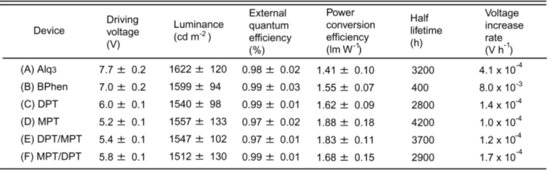
and the MPT ETL, driving voltages and power conversion efficiencies of OLEDs operated at a current density of 50 mA cm-2 are improved from 7.7 ± 0.2 V and 1.41 ± 0.10 lm W-1 (Alq3) to 6.0 ± 0.1 V and 1.62 ± 0.09 lm W-1 (DPT) and 5.2 ± 0.1 V and
1.88 ± 0.18 lm W-1 (MPT), respectively. Half lifetimes of the OLEDs operated at the same current are also enhanced from 3200 h (Alq3) to 4200 h (MPT) by using the MPT
ETL. The reduction in driving voltage is found to arise from more efficient electron injection at interfaces of DPT/cathode (a barrier height of ≈ 0.61 eV) and MPT/cathode (a barrier height of ≈ 0.51 eV) than at an interface of Alq3/cathode (a barrier height of ≈
0.73 eV) as well as better electron mobilities of DPT (8.7 x 10⁻⁵ cm2 V-1 s-1 at an electric field of 5.0 x 10⁵ V cm-1) and MPT (1.4 x 10⁻⁴ cm2 V-1 s-1 at the same field) than that of Alq3 (4.1 x 10⁻⁶ cm2 V-1 s-1 at the same field [Naka et al., Synth. Met. 111-112 (2000)
331.]). A high-mobility electron-transport material of 4,7-diphenyl-1,10-phenanthroline (BPhen) is also used as an ETL for comparison of OLED characteristics.
* Corresponding author. Tel.: +81 761 51 1531; fax: +81 761 51 1149
Although organic light-emitting diodes (OLEDs) have been significantly developed over the last decade [1,2], driving voltages, power conversion efficiencies, and operational stability of OLEDs must be further improved for practical applications, such as flat panel displays. In general, organic materials used for OLEDs are basically insulators having carrier mobilities lower than 10-3 cm2 V-1 s-1 [3-6]. Also, carrier injection barrier heights of several hundred meV are present at heterojunction interfaces of electrode/organic and organic/organic in OLEDs [7,8]. Therefore, high electric fields are required to overcome the low mobilities and the barrier heights, degrading the OLED performances. In particular, electron mobilities are known to be much lower than hole mobilities in most organic materials [3-6]. If a high-mobility electron-transport material (ETM) can be developed, it will be possible to further improve the OLED performances.
Various ETMs have been reported and used to date, such as oxadiazoles [9], triazoles [10], phenanthrolines [11], and triazines [12]. Klenkler et al. recently demonstrated that replacing tris(8-hydroxyquinoline) aluminum (Alq3) with a triazine
compound of 4,4′-bis-[2-(4,6-diphenyl-1,3,5-triazinyl)]-1,1′-biphenyl (BTB) as an electron-transport layer (ETL) can reduce driving voltages of OLEDs from 6.86 V to
4.51 V at a current density of 25 mA cm-2 [13]. Thus, we focus our attention on triazines among the ETMs due to their characteristics of wide energy gaps and high electron transport [13,14]. From results of synthesizing and testing a wide variety of triazine derivatives, 2-biphenyl-4-yl-4,6-bis-(4′-pyridin-2-yl-biphenyl-4-yl)-[1,3,5]triazine (DPT) and 2,4-bis-biphenyl-4-yl-6-(4′-pyridin-2-yl-biphenyl-4-yl)-[1,3,5]triazine (MPT) are found to work as excellent ETLs of OLEDs. The chemical structures of DPT and MPT are shown in Fig. 1. Results of time-of-flight (TOF) measurements reveal that vacuum-deposited films of these triazines have very good electron mobilities of 8.7 x 10⁻⁵ cm2 V-1 s-1 (DPT) and 1.4 x 10⁻⁴ cm2 V-1 s-1 (MPT) at an electric field of 5.0 x 10⁵ V cm-1, which are one-to-two orders of magnitude higher than that of Alq3 (4.1 x 10⁻⁶ cm2
V-1 s-1 at the same field [4,6]), but are slightly lower than that of an ETL material, 4,7-diphenyl-1,10-phenanthroline (BPhen) (5.8 x 10⁻⁴ cm2 V-1 s-1 at the same field [6]). Moreover, higher LUMO (lowest unoccupied molecular orbital) energy levels of DPT (-2.97 ± 0.02 eV) and MPT (-3.07 ± 0.02 eV) lead to efficient electron injection from a cathode when compared with Alq3 (-2.85 ± 0.02 eV) and BPhen (-2.83 ± 0.02 eV). In
other words, the electron mobilities and the electron injection barrier heights can be modified by changing the number of pyridine substitutes in a triazine framework.
In this study, we have shown that driving voltages of OLEDs operated at a current density of 50 mA cm-2 are reduced from 7.7 ± 0.2 V (Alq3) to 7.0 ± 0.2 V (BPhen), 6.0 ±
0.1 V (DPT), and 5.2 ± 0.1 V (MPT) by replacing the typical Alq3 ETL with the ETLs of
BPhen, DPT, and MPT due to the enhanced electron injection and/or transport. Power conversion efficiencies at 50 mA cm-2 are also improved from 1.41 ± 0.10 lm W-1 (Alq3)
to 1.55 ± 0.07 lm W-1 (BPhen), 1.62 ± 0.09 lm W-1 (DPT), and 1.88 ± 0.18 lm W-1 (MPT) due to the voltage reduction mentioned above. Among OLEDs investigated in this study, an OLED with the MPT ETL has the longest lifetime of 4200 h under operation at 50 mA cm-2. For better understanding of the improved OLED performances, details of optical, electrical, and thermal characteristics of DPT and MPT are investigated.
2. Experimental
The devices (A)-(F), whose structures are shown in Fig. 2(a), were fabricated using a vacuum deposition condition as previously reported in Ref. [15]. The ITO, the α-NPD, and the LiF stand for indium tin oxide as a hole-injecting anode layer,
N,N′-diphenyl-N,N′-bis(1-naphthyl)-1,1′-biphenyl-4,4´-diamine as a hole-transport layer
Since use of a very thin hole-injection layer (HIL) of molybdenum oxide (MoO3) can
improve both driving voltages, power conversion efficiencies, and operational stability
of OLEDs [15,18,19], a 0.75 nm MoO3 HIL was introduced between the ITO and the
α-NPD for all devices. The completed devices were encapsulated together with an oxygen and moisture absorbing desiccant sheet using a glass cap and an ultraviolet curing epoxy resin inside a nitrogen-filled glove box. The driving voltages, the current densities, the external quantum efficiencies, the luminance, and the power conversion efficiencies of the devices were measured using conditions as previously reported in Ref. [15]. The changes in voltage and luminance with operational time were measured under dc driving of (A)-(F) at 50 mA cm-2 at room temperature to estimate the voltage increase rates and the half lifetimes, at which the luminance drops to one-half of the initial luminance.
To investigate the electron injection and transport characteristics of Alq3, BPhen,
DPT, and MPT, the electron-only devices (I)-(VIII), whose structures are shown in Fig. 2(b), were fabricated using a similar condition as previously reported in Ref. [15]. To
prevent hole injection from the ITO anode, 2,9-dimethyl-4,7-diphenyl-1,10-phenanthroline (BCP) having a high ionization
potential energy level of -6.25 eV was inserted as a hole-blocking layer (HBL) between the ITO and the ETL in (I)-(VIII). In fact, all electron-only devices exhibited no electroluminescence (EL) during their current density-voltage measurements.
3. Results and discussion
3.1. Optical, electrical, and thermal characteristics of DPT and MPT
The UV-VIS absorption spectra and the fluorescence (FL) spectra of 50 nm films of DPT and MPT on quartz substrates are shown in Fig. 3. The films of DPT and MPT have the almost similar optical characteristics. The absorption peak wavelengths of DPT and MPT are 332 nm and 325 nm, respectively. The FL spectra of the films are nearly mirror images of the absorption spectra. The FL peak wavelengths of DPT and MPT are 431 nm and 424 nm, respectively [20]. Moreover, the ionization potential energy levels of DPT and MPT are measured to be -6.06 ± 0.02 eV and -6.25 ± 0.02 eV, respectively, using an AC-2 photoelectron yield spectrometer (Riken Keiki). The electron affinity energy levels of DPT and MPT are roughly estimated to be -2.97 ± 0.02 eV and -3.07 ± 0.02 eV, respectively, by subtracting the absorption onset energies [≈ 3.09 eV (400 nm) for the DPT film and ≈ 3.18 eV (389 nm) for the MPT film] from the ionization potential energy levels.
The energy-level diagrams of the OLEDs and the electron-only devices estimated using the above-mentioned technique are depicted in Figs. 4(a) and 4(b), respectively.
The smaller-energy-gap layer of Alq3 (≈ 2.86 eV) is sandwiched between the
wider-energy-gap layers of α-NPD (≈ 3.05 eV), BPhen (≈ 3.38 eV), DPT (≈ 3.09 eV), and MPT (≈ 3.18 eV), indicating that Alq3 excitons are well confined in the Alq3 layer.
Moreover, the electron injection barrier heights at the interfaces of Alq3/Al, BPhen/Al,
DPT/Al, and MPT/Al are calculated to be ≈ 0.73 eV, ≈ 0.75 eV, ≈ 0.61 eV, and ≈ 0.51 eV, respectively, from the differences between the electron affinity energy levels of the ETLs and the work function energy level of the Al cathode [Fig. 4(a)]. Comparing these barrier heights, more efficient electron injection is expected to occur at the interfaces of DPT/Al and MPT/Al than at the interfaces of BPhen/Al and Alq3/Al. It is noted that
these barrier heights may be overestimated since a LiF EIL has been used between an ETL and an Al cathode layer to enhance electron injection from Al [17]. However, we suppose that the qualitative comparison of the electron injection characteristics is possible using the above-mentioned barrier heights.
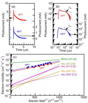
MPT have very good electron transport abilities. The electron mobilities of the films are analyzed using structures of glass substrate/ITO (110 nm)/DPT (870 nm) or MPT (1550 nm)/Al (100 nm) with a TOF measurement condition as previously reported in Ref. [5]. The electron transients of DPT and MPT have less clear plateaus [Fig. 5(a)]. The electron transit time (tTR) of DPT and MPT is estimated from a change in slope in the
double logarithmic plots as shown in Fig. 5(b). The electron mobilities (μ) of the films under a wide range of electric fields are determined from the relationship [4-6] μ =
L2/(tTRV) (1), where L is the cathode-anode spacing and V is the voltage. The μ of these
films is found to be field dependent [Fig. 5(c)]. Here, the field-dependent mobility [4-6] can be expressed as μ = μ0exp(βE0.5) (2), where μ0 is the zero field mobility, β is the
field dependence parameter, and E is the electric field. Fitting the μ-E0.5 plots with Eq (2) yields μ0 = 3.6 x 10⁻⁶ cm2 V-1 s-1 and β = 4.5 x 10⁻³ cm0.5 V-0.5 (DPT) and μ0 = 5.8 x
10-6 cm2 V-1 s-1 and β = 4.5 x 10⁻³ cm0.5 V-0.5 (MPT) [Fig. 5(c)]. It has been shown that electron transients of Alq3 films are changed from a non-dispersive shape to a dispersive
shape by exposing the films to oxygen and water atmosphere [5,21,22]. The μ obtained
from non-dispersive transport (NDT) and dispersive transport (DT) of Alq3
[4,5,6,21,23] and BPhen [6] is plotted together with that of DPT and MPT in Fig. 5(c). The reported μ of Alq3 is slightly dependent upon research groups. As can be seen in Fig.
5(c), the measured μ of DPT and MPT is found to be the intermediate values between those of Alq3 (for example, μ0 = 1.0 x 10⁻⁸ cm2 V-1 s-1 and β = 8.5 x 10⁻³ cm0.5 V-0.5
[4,6]) and BPhen (μ0 = 2.0 x 10⁻⁴ cm2 V-1 s-1 and β = 1.5 x 10⁻³ cm0.5 V-0.5 [6]) and is,
however, comparable to those of triazine compounds previously reported [13,24,25].
The thermal characteristics of DPT and MPT are investigated using differential scanning calorimetry (DSC 200, SEIKO). The measured glass transition temperatures of DPT and MPT are 136 ºC and 108 ºC, respectively, and the measured melting temperatures of DPT and MPT are 340 ºC and 279 ºC, respectively. The observed high glass transition temperatures are expected to provide high thermal stability for the OLEDs operated at elevated temperature.
3.2. Injection and transport of electrons in OLEDs and electron-only devices
We investigate that how the use of the ETLs of Alq3, BPhen, DPT, and MPT
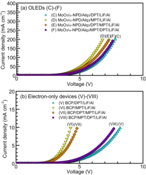
affects the driving voltages of the OLEDs. The current density-voltage characteristics of (A)-(D) are shown in Fig. 6(a). The driving voltages of (A)-(D) operated at a current density of 50 mA cm-2 are summarized in Table I. Replacing the Alq3 ETL with the
mA cm-2. Since the electron injection barrier heights at the interfaces of Alq3/Al (≈ 0.73
eV) and BPhen/Al (≈ 0.75 eV) are almost similar, the voltage reduction is attributable to the highest electron mobility observed in the BPhen ETL [Fig. 5(c)]. On the other hand, the driving voltages at 50 mA cm-2 are reduced from 7.7 ± 0.2 V (A) to 6.0 ± 0.1 V (C)
and 5.2 ± 0.1 V (D) by replacing the Alq3 ETL with the DPT ETL and the MPT ETL
due to the decrease in electron injection barrier height from ≈ 0.73 eV (Alq3/Al) to ≈
0.61 eV (DPT/Al) and ≈ 0.51 eV (MPT/Al) as well as the increase in electron mobility by one-to-two orders of magnitude [see Fig. 5(c)]. Although the electron mobility of the BPhen ETL is higher than those of the DPT ETL and the MPT ETL, the driving voltage of (B) with the BPhen ETL (7.0 ± 0.2 V) becomes higher than those of (C) with the DPT ETL (6.0 ± 0.1 V) and (D) with the MPT ETL (5.2 ± 0.1 V), indicating that the decrease in electron injection barrier height is more advantageous than the increase in electron mobility to reducing the voltages. To double-check the change in the driving voltages of (A)-(D), the electron-only devices (I)-(IV), the structures of which are shown in Fig. 2(b), were fabricated and tested. The current density-voltage characteristics of the electron-only devices (I)-(IV) [Fig. 6(b)] are found to be changed in the manner similar to those of the OLEDs (A)-(D) [Fig. 6(a)].
As discussed in the previous section 3.1., the difference in the electron injection barrier height between the interfaces of DPT/cathode and MPT/cathode is only ≈ 0.1 eV. Also, the ratio of the mobility of the MPT ETL to the mobility of the DPT ETL is as small as ≈ 1.6. Therefore, we investigate that either electron injection or electron transport plays an important role in improving the driving voltage of (D) relative to (C). To do this, the current density-voltage characteristics of the OLEDs (C)-(F) and the electron-only devices (V)-(VIII) are compared [Figs. 7(a) and 7(b)]. The structures of (C)-(F) and (V)-(VIII) are also shown in Figs. 2(a) and 2(b), respectively. Using a 5 nm MPT ETL between the DPT ETL and the LiF EIL leads to a reduction in the driving voltage from 6.0 ± 0.1 V (C) to 5.4 ± 0.1 V (E). On the other hand, the driving voltages increase from 5.2 ± 0.1 V (D) to 5.8 ± 0.1 V (F) by inserting a 5 nm DPT ETL between the MPT ETL and the LiF EIL. The similar change in voltage is observed in the electron-only devices (V)-(VIII). In general, while transport-limited currents (such as space-charge-limited currents) are changed proportional to carrier mobilities [26], injection-limited currents (such as tunneling injection currents and thermionic emission currents) exponentially increase with decreasing barrier heights [7,27,28]. From these, we infer that the decrease in electron injection barrier height by ≈ 0.1 eV predominantly reduces the driving voltages of the OLEDs than the increase in electron mobility by ≈
1.6 times, which is in good agreement with the results discussed previously using the BPhen ETL.
In all devices, we observed green EL from electrically excited Alq3 molecules.
The shapes and the peak tops (528-530 nm) of the EL spectra are consistent with those previously reported [16,29,30] and they are independent of current densities. A carrier recombination efficiency of electrons and holes in a carrier recombination zone is known to affect current density-voltage characteristics [26]. However, the external quantum efficiencies of (A)-(F) at 50 mA cm-2 are almost similar (≈ 1%) (Table I), indicating that a change in carrier recombination efficiency causes a negligible effect on the driving voltages of the OLEDs. On the other hand, the power conversion efficiencies at 50 mA cm-2 are improved from 1.41 ± 0.10 lm W-1 (A) to 1.88 ± 0.18 lm W-1 (D) due to the voltage reduction discussed above (Table I).
3.3. Operational stability of OLEDs
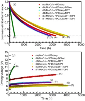
The luminance/initial luminance-time (L/L0-t) characteristics and the driving
voltage-time (V-t) characteristics of (A)-(F) are shown in Figs. 8(a) and 8(b), respectively. The half lifetimes of the OLEDs are determined to be 3200 h (A), 400 h
(B), 2800 h (C), 4200 h (D), 3700 h (E), and 2900 h (F) (Table I) from Fig. 8(a) [31]. Moreover, the straight-line approximation of the V-t curves [the solid lines in Fig. 8(b)] gives the voltage increase rates: 4.1 x 10⁻⁴ V h-1 (A), 8.0 x 10⁻³ V h-1 (B), 1.4 x 10⁻⁴ V h-1 (C), 1.0 x 10⁻⁴ V h-1 (D), 1.2 x 10⁻⁴ V h-1 (E), and 1.7 x 10⁻⁴ V h-1 (F) (Table I). The longest half lifetime of 4200 h and the lowest voltage increase rate of 1.0 x 10⁻⁴ V h-1 obtained in (D) are excellent values when compared with previously reported OLEDs based on α-NPD and Alq3 [15,16].
Replacing the Alq3 ETL with the MPT ETL increases the half lifetimes from 3200
h (A) to 4200 h (D). Although the half lifetime of (C) with the DPT ETL (2800 h) is
lower than that of (A) with the Alq3 ETL (3200 h), inserting the 5 nm MPT ETL
between the DPT ETL and the LiF EIL (the DPT/MPT/LiF unit) enhances the lifetimes from 2800 h (C) to 3700 h (E). On the other hand, the lifetimes are degraded from 4200 h (D) to 2900 h (F) by using the MPT/DPT/LiF unit. In the case of the BPhen ETL, the device (B) has the shortest lifetime of 400 h among the devices. From these results, inserting the MPT layer between the ETL and the LiF EIL is found to be more important for the operational stability of the OLEDs than using the layers of Alq3, BPhen, and
the proposed degradation models cannot fully explain the lifetime results obtained in this work. Detailed degradation mechanisms of the OLEDs are now under investigation.
4. Conclusions
We have shown that triazine films of DPT and MPT have very good electron mobilities of 8.7 x 10⁻⁵ cm2 V-1 s-1 (DPT) and 1.4 x 10⁻⁴ cm2 V-1 s-1 (MPT) at an electric field of 5.0 x 10⁵ V cm-1, which are much higher than that of Alq3 (4.1 x 10⁻⁶ cm2 V-1 s-1
at the same field [4,6]), but are slightly lower than that of BPhen (5.8 x 10⁻⁴ cm2 V-1 s-1 at the same field [6]). Moreover, the triazine films have higher LUMO energy levels of -2.97 ± 0.02 eV (DPT) and -3.07 ± 0.02 eV (MPT) than the films of Alq3 (-2.85 ± 0.02
eV) and BPhen (-2.83 ± 0.02) have, resulting in that electron injection at interfaces of DPT/cathode and MPT/cathode is more facile than that at interfaces of Alq3/cathode and
BPhen/cathode. By comparing performances of OLEDs having the ETLs of Alq3,
BPhen, DPT, and MPT, a decrease in electron injection barrier height at the ETL/cathode interfaces is found to predominantly reduce driving voltages of the OLEDs than an increase in electron mobility of the ETLs. Thus, the OLED having the MPT ETL has the lowest driving voltage of 5.2 ± 0.1 V, the highest power conversion efficiency of 1.88 ± 0.18 lm W-1, and the longest half lifetime of 4200 h at a current
density of 50 mA cm-2 among the OLEDs investigated in this study. These results indicate that MPT with the high electron mobility and the high LUMO energy level is a promising candidate for use as an ETL for fabricating high-performance OLEDs.
References
[1] S. R. Forrest, Nature (London) 428 (2004) 911. [2] N. Koch, Chem. Phys. Chem. 8 (2007) 1438.
[3] M. Kitamura, T. Imada, S. Kato, Y. Arakawa, Jpn. J. Appl. Phys. 43 (2004) 2326. [4] S. Naka, H. Okada, H. Onnagawa, Y. Yamaguchi, T. Tsutsui, Synth. Met. 111-112
(2000) 331.
[5] G. G. Malliaras, Y. Shen, D. H. Dunlap, H. Murata, Z. H. Kafafi, Appl. Phys. Lett. 79 (2001) 2582.
[6] S. Naka, H. Okada, H. Onnagawa, T. Tsutsui, Appl. Phys. Lett. 76 (2000) 197. [7] I. D. Parker, J. Appl. Phys. 75 (1994) 1656.
[8] T. Matsushima, K. Goushi, C. Adachi, Chem. Phys. Lett. 435 (2007) 327. [9] C. Adachi, T. Tsutsui, S. Saito, Appl. Phys. Lett. 55 (1989) 1489.
[10] J. Kido, C. Ohtaki, K. Hongawa, K. Okuyama, K. Nagai, Jpn. J. Appl. Phys. 32 (1993) L917.
[11] H. Nakada, S. Kawami, K. Nagayama, Y. Yonemoto, R. Murayama, J. Funaki, T. Wakimoto, K. Imai, Polym. Prepr. Jpn. 35 (1994) 2450.
[12] R. Fink, C. Frenz, M. Thelakkat, H.-W. Schmidt, Macromol. 30 (1997) 8177. [13] R. A. Klenkler, H. Aziz , A. Tran, Z. D. Popovic, G. Xua, Org. Electron. 9 (2008)
285.
[14] H. Inomata, K. Goushi, T. Masuko, T. Konno, T. Imai, H. Sasabe, J. J. Brown, C. Adachi, Chem. Mater. 16 (2004) 1285.
[15] T. Matsushima, G.-H. Jin, H. Murata, J. Appl. Phys. 104 (2008) 051501. [16] S. A. Van Slyke, C. H. Chen, C. W. Tang, Appl. Phys. Lett. 69 (1996) 2160. [17] L. S. Hung, C. W. Tang, M. G. Mason, Appl. Phys. Lett. 70 (1997) 152. [18] T. Matsushima, Y. Kinoshita, H. Murata, Appl. Phys. Lett. 91 (2007) 253504. [19] T. Matsushima, H. Murata, J. Appl. Phys. 104 (2008) 034507.
[20] FL quantum efficiencies of films of DPT and MPT are measured to be 55 ± 1% and 54 ± 1% using an integrating sphere system (C9920, Hamamatsu Photonics).
[21] S. C. Tse, H. H. Fong, S. K. So, J. Appl. Phys. 94 (2003) 2033. [22] H. H. Fong, S. K. So, J. Appl. Phys. 98 (2005) 023711.
[23] R. G. Kepler, P. M. Beeson, S. J. Jacobs, R. A. Anderson, M. B. Sinclair, V. S. Valencia, P. A. Cahill, Appl. Phys. Lett. 66 (1995) 3618.
[24] Y.-D. Zhang, K. G. Jesperson, M. Kempe, J. A. Kornfield, S. Barlow, B. Kippelen, S. R. Marder, Langmuir 19 (2003) 6534.
[25] T. Yamamoto, S. Watanabe, H. Fukumoto, M. Sato, T. Tanaka, Macromol. Rapid Commun. 27 (2006) 317.
[26] M. A. Lampert, P. Mark, Current Injection In Solids (ACADEMIC, New York, 1970).
[27] R. H. Fowler, L. Nordheim, Proc. R. Soc. London Ser. A 119 (1928) 173. [28] T. Matsushima, C. Adachi, Thin Solid Films 516 (2008) 5069.
[29] T. Dobbertin, M. Kroeger, D. Heithecker, D. Schneider, D. Metzdorf, H. Neuner, E. Becker, H.-H. Johannes, W. Kowalsky, Appl. Phys. Lett. 82 (2003) 284.
[30] P.-C. Kao, S.-Y. Chu, Z.-X. You, S. J. Liou, C.-A. Chuang, Thin Solid Films 498 (2006) 249.
[31] Luminance decay curves shown in Fig. 8(a) are well fitted using stretched exponential decay equation, which is given by L/L0 = exp[-(t/τ)α], where τ and α is
fitting parameters [C. Féry, B. Racine, D. Vaufrey, H. Doyeux, S. Cinà, Appl. Phys. Let. 87 (2005) 213502].
Table I. Driving voltages, luminance, external quantum efficiencies, power conversion efficiencies, half lifetimes, and voltage increase rates of (A)-(F) operated at 50 mA cm-2.
Figure captions
Fig. 1. Chemical structures of molecules of DPT and MPT.
Fig. 2. Schematic structures of (a) OLEDs (A)-(F) and (b) electron-only devices (I)-(VIII).
Fig. 3. UV-VIS absorption spectra and FL spectra of vacuum-deposited films of DPT and MPT on quartz substrates. FL spectra were measured using excitation light wavelengths at absorption maxima.
Fig. 4. Energy-level diagrams of (a) OLEDs (A)-(F) and (b) electron-only devices (I)-(VIII).
Fig. 5. (a) Double linear plots and (b) double logarithmic plots of TOF electron transients from DPT and MPT at electric field of 5.8 x 10⁵ V cm-1 and (c) electric field dependence of TOF electron mobilities of DPT and MPT, which is compared with that of previously reported TOF electron mobilities estimated from dispersive transport (DT) and non-dispersive transport (NDT) of Alq [4,5,6,21,23] and DT of
BPhen [6].
Fig. 6. (a) Current density-voltage characteristics of (a) OLEDs (A)-(D) and (b) electron-only devices (I)-(IV).
Fig. 7. (a) Current density-voltage characteristics of (a) OLEDs (C)-(F) and (b) electron-only devices (V)-(VIII).
Fig. 8. (a) Luminance/initial luminance-time characteristics and (b) driving voltage-time characteristics of OLEDs (A)-(F) operated at 50 mA cm-2.
Fig. 1. Matsushima et al.
Fig. 2. Matsushima et al.
Fig. 3. Matsushima et al.
Fig. 4. Matsushima et al.
Fig. 5 Matsushima et al.
Fig. 6 Matsushima et al.
Fig. 7 Matsushima et al.
Fig. 8 Matsushima et al.