Dynamics of Hydrogen Hydrates
著者 ユダ アーマン
著者別表示 Yudha Arman journal or
publication title
博士論文本文Full 学位授与番号 13301甲第4812号
学位名 博士(理学)
学位授与年月日 2018‑09‑26
URL http://hdl.handle.net/2297/00053022
Creative Commons : 表示 ‑ 非営利 ‑ 改変禁止 http://creativecommons.org/licenses/by‑nc‑nd/3.0/deed.ja
Theoretical Study on the Structure and Dynamics of Hydrogen Hydrates
Graduate School of
Natural Science & Technology Kanazawa University
Division of Mathematical and Physical Sciences
Student ID Number: 1524012015 Name: Yudha Arman
Chief Advisor: Shinichi MIURA, Prof.
Date of Submission: June 28
th, 2018
Molecular dynamics study of hydrogen hydrates C1and C2known as filled ice II and Ic, respectively, have been performed. The structure of this two hydrates is closely similar to the respective ice structure encapsulating hydrogen molecule in a lattice site constructed by the framework of hydrogen-bonded water molecules. The hydrates were calculated under temperature condition controlled at 291 K. The pressure of 1 GPa for C1 and 4 GPa for C2 was carried out adopting the experimental arrangement where the fast diffusion of hydrogen molecules was observed; here, the H2:H2O stoichiometry of 1:6 was used for C1and 1:1 for C2. There are two calculation setups have been carried out, namely full occupation and one vacancy setup, to demonstrate the ideally synthesized and the occupation’s defect hydrates, respectively. Longtime simulation has been done to study the diffusion process; here, 100 ns for full occupation and 50 ns for one vacancy setup. In the calculation, many inter-site translations were observed only in the one vacancy setup of both hydrates. This behavior indicates the necessity of occupation’s defect to facilitate the diffusion. The calculated hydrogen molecule diffusion coefficient was found to be in good agreement with the experimental results confirming the highly anisotropic diffusion for hydrate C1while isotropic for C2.
Contents
Chapter 1 Introduction 1
1.1 Purpose . . . 5
1.2 Dissertation Organization . . . 6
Chapter 2 Ice and Clathrate Hydrate 7 2.1 Ice . . . 7
2.2 Clathrate Hydrate . . . 10
2.3 Filled Ices . . . 12
Chapter 3 Molecular Dynamics Calculation 15 Chapter 4 Results and Discussion 20 4.1 Equilibrium Condition . . . 20
4.2 Energy and Density . . . 24
4.3 Diffusion Mechanism . . . 26
4.4 Radial Distribution Function . . . 34
4.5 Infra Red (IR) Spectra . . . 38
Chapter 5 Concluding Remarks 43 5.1 Summary . . . 43
5.2 Future Work . . . 45
A Mathematical Backgrounds of MD 47 A.1 Periodic Boundary Condition . . . 48
A.2 Long Range Interactions . . . 48
A.3 Thermostat and Barostat . . . 61
A.4 Barostating . . . 74
A.5 Liouville formulation for Time Reversible Integrator . . . 76
A.6 Constraints . . . 82
B Diffusion Coefficient Code 92
C Potential Energy Map of Trial Guest Position Calculation 97
D Infra Red Spectra Calculation Code 107
References 109
Acknowledgment 118
List of Figures
1.1 Molecule model for C1system. Green spheres describe hydrogen guest. . 4 1.2 Molecule model for C2system. Green spheres describe hydrogen guest. . 5 2.1 Clathrate hydrate structure of (a) sI, (b) sII and (c) sH. . . 11 2.2 Clathrate hydrate structure of tetragonal (a) s - T [58], (b) s - K [59] and
(c) s - III [60]. Green spheres indicates guest molecules. . . 12 2.3 MH-III structure [64]. . . 13 2.4 Filled ice structure of (a) C0 [61] (b) C1 and (c) C2. Red and Green
spheres indicate oxygen atoms and guest molecules, respectively. Grey line describes hydrogen bond connecting water frameworks. C1 and C2
systems are redraw with ice configurations taken from Buch et al. [71]
while guest molecules are included without energy minimization. Both structures are viewed along hexagonal puckered-plane . . . 14 3.1 Molecule model for (a) water framework, and (b) guest molecule . . . 17 3.2 The arrangement of oxygen atoms (red spheres) and H2 molecules (green
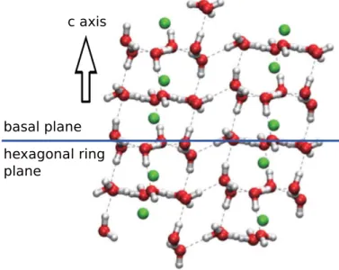
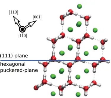
spheres) in (a) hydrate C1 and (b) C2. Hydrate C1 is viewed parallel to the basal plane and C2 on (110) plane. Bond connecting the adjacent oxygen atoms and hydrogen molecules are drawn to clarify the structural configuration with the distance criteria 3.0 ˚A for hydrate C1 and 2.8 ˚A for C2. . . 19 4.1 Time series plot of Molecular dynamics calculation result on (a) total
energy, (b) pressure, (c) temperature, (d) and potential energy C1 full occupation system during 3 ns of production run. Grey line indicates instantaneous value while blue line for average. . . 21 4.2 Time series plot of Molecular dynamics calculation result on (a) total en-
ergy, (b) pressure, (c) temperature, (d) and potential energy of C2 one vacancy system during 3 ns of production run. Grey line indicates instan- taneous value while blue line for average. . . 22 4.3 Time series plot of (a) total energy, (b) pressure, (c) temperature, (d)
and potential energy in full occupation of hydrate C2 during 10 ns of production run. Grey line indicates instantaneous value while blue line for the average. . . 23
4.4 Time series plot of (a) total energy, (b) pressure, (c) temperature, (d) and potential energy in one vacancy setup of hydrate C2 during 1 ns of production run. Grey line indicates instantaneous value while blue line for average. . . 24 4.5 The arrangement of water and hydrogen molecules in hydrate C2. Water
molecules are drawn by the red-white licorice shapes and H2 molecules described by the green spheres. Hydrogen bond connecting the water molecules is shown by dashed gray line. Text on the box explains the drawing plane of the framework; here, the system is drawn on (a) (100) and (b) (1¯10) plane. Blue lines crossing the structure and the text next to the line show the crystallographic surfaces in which characterize the system. Red arrow is pointing direction of [110] as illustrate in the figure. 28 4.6 Trajectory of the most frequent guest molecules to do inter-site translation
in (a) C1 (b) C2of one vacancy system. Water molecule’s framework are shown by the red-white licorice shapes. Black solid line represents the path taken by a tagged guest molecules during 50 ns of calculation time.
Hydrate C1 is viewed along (1¯21) of ice II (rhombohedral unit cell with spacegroup R¯3) and C2 is drawn on (110) plane. . . 30 4.7 Snapshot of a guest molecule performing inter-site hopping in orthographic
view for one vacancy system of (a) C1 and (b) C2. Dashed black lines indicate hydrogen bonds while blue arrows show the direction. Colored spheres (green, blue and yellow) are for guest molecules. In both figures, spheres with similar color are used to represent the same hopping scheme in successive time. In the case of C1system, both yellow spheres indicate the guest movement along the crystallographic c axis. inter-site hydrogen guest trajectory parallel to the (0¯11) plane shown by yellow and blue spheres in C2system, while the movement to the (011) plane is represented by green spheres. . . 31 4.8 Mean square displacement (MSD) as a function of timetfor (a) hydrogen
molecules in one vacancy system of filled ice II and Ic, and (b) vacant site of hydrate C1 and C2. . . 32
4.9 Potential Energy contour of one vacancy C1system, snapshots are drawn at 0.36619 ns on projection surface parallel to (a) basal and (b) optical plane. On the basal plane, 10 contour lines are used with the lowest energy to describe is 1 kcal/mol and 2.6 ×10⁵ kcal/mol for the highest. On the other hand, 14 contour lines are used on the optical plane in which the lowest energy to represent is 6.25 ×10⁻³ kcal/mol. Hydrogen guest and oxygen-water molecules that are projected on the plane are represented by gray rectangles and black spheres, respectively. Black triangle as shown in C2system is also used to describe the hydrogen guest molecule to have inter-site movement in the next consecutive time-frame. Red sphere is drawn to denote the vacancy location. As previously shown by the C2
system, the tagged hydrogen guest to jump in this C1 system is located in the area having the lowest potential energy value. In the case of energy map on optical plane, the lowest energy area spanned wider surfaces to cover empty lattice site to occupy in the next consecutive time-frame. In contrast, the lowest energy area on the basal plane is shown very small to cover both the position of tagged hydrogen molecule and the vacancy.
Energy barrier built around the triangle restricted the diffusion process to occur on this basal plane. . . 33 4.10 Contour plot of one vacancy hydrogen hydrate C2potential energy drawn
on surface parallel to (a) hexagonal (110) plane at 0.40106 ns and (b) (¯110) plane at 0.60572 ns. There are 8 isolines to describe potential energy map for the hexagonal puckered-surface, with the lowest value describing by the line having potential energy of 64 kcal/mol. Similar to the previous plane, eight increasing pair potential energy lines are used to describe the map on the normal. The plotted energy line represent energy value started from 16 kcal/mol. In both figures, guest molecule to do inter-site movement in the next time-frame is represented by a black triangle while the vacancy is denoted by red sphere. The lowest energy area where the hopping candidate is located to cover spaces where the vacancy is settled.
Black spheres and gray rectangles denote the projected oxygen-water and other hydrogen guest molecules on the plane, respectively. . . 34 4.11 Radial distribution function plot of (a) Ow-Ow, (b) Ow-Hw, (c) Ow-Hg2(d)
Hw-Hw, (e) Hw-Hg2, and (f) Hg2-Hg2 pairs in C1 system. . . 35 4.12 Radial distribution function plot of (a) Ow-Ow, (b) Ow-Hw, (c) Ow-Hg2,
(d) Hw-Hw, (e) Hw-Hg2, and (f) Hg2-Hg2pairs in C2 system. . . 36 4.13 Geometry of hydrogen bonding criteria used in the calculation . . . 37 4.14 IR Spectra from total dipole moment correlation function of hydrate (a)
C1 and (b) C2 system. . . 40 A.1 Illustration of Ewald Summation . . . 51
A.2 Illustration of Thermostating in Molecular dynamics for (a). General de- scription, (b). Nos´e-Hoover method, and (c). Nos´e-Hoover chain method 63
List of Tables
3.1 The potential parameter for water and hydrogen guest molecules used in MD calculation. For H2 guest molecule, both LJ and charge site are located at the same center of mass. Meanwhile, Oxygen atom’s position of water molecule is used as LJ calculation point while the negative charge
placed at M position, located between the center of H-H and Oxygen. . . 15
3.2 Host Framework Setup . . . 16
3.3 Hydrogen molecules and NPT Condition . . . 18
4.1 Energy Comparison . . . 25
4.2 System’s Density . . . 26
4.3 Diffusion coefficient of hydrogen molecules (D) and vacancy (Dvac) in units of cm2s−1. C1 and C2 are for filled ice II and Ic, respectively. . . . 27
4.4 Hydrogen Bond Distance and Energy . . . 39
4.5 IR Spectra’s peaks comparison . . . 42
Chapter 1
Introduction
Nowadays, the long-term mining and usage of unrecoverable fossil energy have made several issues regarding human safety and environment. From the early beginning of production line, the severe impact already noticeable. The spill of the crude product has been reported to give immense implications to surroundings. Ecological problems were generated by the calamity. Also, the release of natural gas in numerous location during exploitation has given more damage to the environment. When concerning the usage, the imperfect combustion systems have released hazardous byproduct. At the early stage of contamination, one would argue that this could be responsible for the several known significant impacts. Eventually, the accumulative disadvantages have expanded massively threatening many life aspects. In several cases, the level content beyond the safety measure of this hazardous byproduct is reported evidence in the air [1, 2]. The critical term is labeled to substances which can implicitly and explicitly be threatening the life-supporting condition. Also, greenhouse effect generated by CO2 accumulation is now becoming a commonly-heard issue [3]. The fossil fuel burning contributes to the released of CO2 into the atmosphere.
Less consciousness to make a substitute substance previously shown for an extended period. Since this fossil fuel is the primary source of energy, this unrecoverable substance exploited numerously. As a result, the supply has primarily reduced to be predicted less portion will be left over to sustain the future needs. Concerning this point, awareness to find the substitution candidate has attracted intensive studies. Also, the unwilling effect regarding human safety has given more attention towards the finding. Several aspects are declared to be the necessity during the discovery. The alternative substance should be renewable and efficient. Again, the derivatives produced during the usage should be environmentally clean.
First of all, the review of the replacement candidate is starting at the basic of the carrier itself. There are two known energy carriers, namely electricity and hydrogen. Despite being the lightest and smallest molecule with bond distance is 0.74 ˚A, the diatomic H2
have the highest energy content regarding the weight while showing the lowest concerning the volume. Hydrogen also has higher efficiency and easy to store in different ways, thus potentially to be used as a new energy source providing low polluting fuel. This source of energy can be transported and heated in the places where the electricity is hard to
generate. Also, it is practically cheaper to deliver hydrogen with pipeline compared to the long distance wired electricity distribution. When one considering the use of materials encapsulating hydrogen in transporting, efficiency will grow higher. Space shuttle mainly uses hydrogen to produce energy and pure water fuel-cell for the crew.
Hydrogen is bonded into compounds by other molecules. The bonding substance is then can be separated to give H2 exist in gas phases employing electrolysis, steam reforming, photo-electrolysis and biomass gasification. The respective hydrogen gas can be directly used or be kept in a container to harvest the energy. Compression is needed to maintain hydrogen in the gas phase. The compressed hydrogen, therefore, can be stored in a tube to be delivered or fed into the pipeline network. Given this point, it is advantages to have porous materials which can encapsulate a significant amount of gaseous hydrogen.
Again, the ability to be synthesized and kept in ambient pressure and temperature would gain substantial potential benefits. Additionally, to be practical, it is crucial to have host structure able to accommodate hydrogen molecules without having chemical mixtures.
Recent studies have proposed several substances to be the proper candidate.
Clathrate hydrate is a crystalline ice material constructed from frozen water molecules accommodating guest molecules. The arrangements assembling cage-like framework in which light noble gaseous or liquid can be encapsulated [4, 5]. The guest molecules which have substantial hydrophobic moiety trapped inside these polyhedral cavities through single and multiple occupations per cage. The encapsulation performed without having the chemical mixture, preventing the host to collapse when positive external pressure is applied [6]. Guest in the gas phase is kept inside cages only by physical bonds. These guest encapsulations have made the resulted structure in a broaden phase-space stability compared to the respective metastable empty structure. These encapsulations were also preventing the cages not to rupture to the typical ice crystal structure or liquid water. This behavior, in the view of the statistical study of several clathrate hydrate systems, were correlated with the van der Waals volume and dipole moment of gaseous species [7]. The strong correlation was shown by the two-phase equilibrium variables, namely dissociation heat and pressure dissociation of ice point. Meanwhile, van der Waals volume of gas species was ranked as the second and third to contribute to the heat and pressure dissociation shifting from unoccupied ice structure, respectively. Compared to the previously discussed variables involved in the reported study, the dipole moment of guest molecule gives lesser influence to the clathrate phase equilibrium. The guest molecules along with hydrogen- water atom released during melting. These remarkable features attract interest towards the study in producing more efficient hydrogen storage materials. To further extent, understanding the physical and dynamic interaction between the foreign molecules and the water framework as host is required.
In the early stage of hydrogen storage research, clathrate hydrates compound were the less known candidate to be proposed and considered to be studied. The flow-line problems occurred in the natural gas exploitation have turned this solid compound into the famously noticeable subject to study; under high pressure and low-temperature, the clathrates built-up formed inside pipeline blocked the gas distribution [8]. Also, Geohazard of the
dissociation of gas hydrate originated from the deep-water deposits have made broaden attention to the clathrate hydrates towards serious interest regarding human safety [9,10].
However, despite the unexpected findings that famously introduce clathrate hydrates, a recent study discovered the potential of this practical host-structure containing gaseous molecules, in particular as the solution of CO2removal [11] and hydrogen storage materials [12–16]. The later attracts relentless study to meet the demands of efficient, renewable and clean energy sources. Moreover, theoretical study and experimental findings of hydrogen hydrate revealed the ability of hydrogen to form clathrate hydrate through single and multiple occupancies [17, 18]. This finding against previous believed which stated that inclusion of hydrogen guest was unable to stabilize cage due to its small molecular size.
This flawed suggestion of inability due to hydrogen size had spanned for a long time.
There have been several observations noticing advantages from hydrogen hydrate. This material is a non-explosive substance in which essential concerning transportation and handling safety. Also, clean by-products have resulted from the energy harnessing; here, only water and a small concentration of promoters produced. During harnessing, the hydrogen guest is released from the framework through the pressure reduction and small temperature adjustment. This energy carrier stays in its molecular form inside the cage.
Moreover, several published data showed that hydrogen hydrate was able to form in the moderate temperature and condition with the need of low promoters concentration; sub- stances such as THF [19, 20], Acetone [21] with low concentration were used to improve operating conditions. These reveal potential features on having hydrogen storage eco- nomically with less energy effort in controlling synthesize process. There also numerous hydrogen hydrate having higher hydrogen content per unit mass and volume had been discovered. [12, 13, 22, 23]
However, several challenges had been experienced to make outstanding efforts on having clathrate hydrate as hydrogen storage. The duration of time to synthesize the compound featured in several hydrogen hydrates due to the reluctant of formation kinetic obligate effort to show less effectiveness. Stability issue at ambient thermodynamic condition showed similar high effort lineaments of hydrogen hydrate. Also, when one include pro- moters to have a better operating condition, storage capacity will be reduced since these molecules occupying the available spaces. Many studies have been conducted to overcome the limitation. However, a deduction of one aspect should be made when gaining the other [24].
Hydrogen gas can also be found encapsulated in the cage-like water framework without the need of promoters to support. For instance, high amount of hydrogen gas can be stored in lattice sites of ice II and Ic, with H2: H2O stoichiometry is 1:6 and 1:1, respectively [23].
Instead of clathrate hydrate, these two known as filled ices of C1and C2, respectively. The inclusion stabilizes the ice structure in an extended range of pressure and temperature compared to the unfilled composition [25–29]. Hydrate C1is firmly having ice II structure while hydrate C2 shows cubic ice framework. Not only hydrogen, other light noble gas molecules can also be occupied [30, 31]. However, the high-pressure condition is needed when synthesizing the materials to compensate the interaction energy between guest and
surrounding host molecules which shows repulsive character due to the small size of lattice site. The guests themselves are needed to stabilize the host-framework structure. The high ratio between host-guest is a necessity to avoid lattice site’s rupture when highly needed pressure is applied to the system.
The crystal structure of hydrogen hydrate C1 is known to be rhombohedral in theR¯3 space group. It can also be viewed as the hexagonal unit cell by using Miller indices relation−h+k+l= 3nwherenis an integer. Under 2.1 GPa and 295(3) K, this hydrate was reported to have a hexagonal unit cell containing 36 water molecules [23]. The full arrangement consists of the hexagonal array of hydrogen-bonded water molecules lies on the surface known as the basal plane. The planes are piled along the optical c axis to form hexagonal tube-like columns in a similar way as the ice II.
Fig. 1.1.Molecule model for C1 system. Green spheres describe hydrogen guest.
On the other hand, under 3.1 GPa of pressure, hydrogen hydrate C2 was reported to have a cubic crystal structure [23]. The arrangement of water molecules gives eight faces forming diamond-like crystal structures. Surfaces containing hexagonal shaped of hydrogen-bonded water molecules are formed by stacking (111) faces in a disordered way along (110) direction. This (111) plane is similar to the unoccupied cubic ice structure and perfectly coherent to the basal plane of hexagonal ice [32]. The hydrate was able to store maximum 10%wt H2 capacity equivalent to 1:1 molar ratio between hydrogen and host water framework. The stoichiometry gives C2 characterized as a hydrogen-rich material compound, thus suitable for hydrogen storage.
Fast diffusion of hydrogen guest molecules has been reported in these dense hydrates under highly compressed condition [33, 34]. The observed rapid hydrogen molecules inter- site translation is comparable to the molecular diffusion in a liquid state with less affected by the pressure. Moreover, concerning the diffusion trajectory, anisotropic is suggested in hydrate C1 while isotropic is for hydrate C2. This suggestion was governed from more to the structural arrangement’s consideration rather than theoretically observed. The details
Fig. 1.2.Molecule model for C2 system. Green spheres describe hydrogen guest.
mechanism could be crucial in designing better hydrogen storage in these filled ices. There could be a factor to drive these guests diffusion among polyhedral cavity.
There are several fascinating aspects regarding molecular encapsulation in ice- resembling structure. In clathrate hydrate systems, the guest to diffuse is placed in polyhedral cavities of ice structure through weak Van der Waals interaction. Correspond- ingly, no chemical mixture is observed. The dimension size of the polyhedral enclosure is reported to give influence in the number of occupation and the guest mobility. It is therefore needed to have a microscopic understanding of this interaction for several applications. In the development of hydrogen storage, numerous study gives evidence on the importance of structural size in the intra-cage dynamics [35]. Moreover, in the specific system such as filled ices, the small size of lattice site give high repulsion characteristic shown by the guest-host interaction [29]. Therefore, high pressure is needed to compensate the confinement. As a consequence of the pressurization, more dynamic is expected to be observed since the density of guest molecule is denser compared to its condensed state. Imperfect confinement structure also influenced the mobility of the confined species. Inter-site translation is observed in clathrate hydrate by this kind of water vacancy [36, 37]. With the defect, free energy of lattice site’s boundary is lowering to allow the guest to diffuse.
1.1 Purpose
This research is performed to theoretically study the dynamical properties occurred in hydrogen-filled ice II and Ic. Both systems can be considered as a hydrogen-rich mate- rial compound where rapid diffusion of the guest was found with less influenced by the pressure. It has been suggested that hydrogen molecules are denser compared to their
condensed phase under this condition. This dynamics-related structure-governing kinetics is useful to be studied. They determine the duration time of synthesizing and the disso- ciation process. The same rapid diffusion of guest molecules should be captured in the calculation to justify the provided evidence of microscopic details of hydrogen molecule’s dynamic in this study.
In this doctoral thesis document, the report of the molecular dynamics (MD) calcula- tion result of hydrogen hydrate C1 and C2 will be presented. There are several confirma- tion points of the previous observations in C1 and C2 structures and relevant additional information of diffusion mechanism provided to be done. Also, details of a long time MD calculation when investigating the inter-site diffusion of the encapsulated hydrogen molecules is discussed. There were two different setups on each of the filled ices structure.
Systems with the maximum load of hydrogen guest molecules were the first system to simulate while single lattice site left unoccupied be the second. These setups were deliv- ered based on the results of a vacancy-driven diffusion that had been studied extensively in numerous clathrate hydrate systems [37–39]. The result was suggesting the necessity of an imperfect guest occupation in ice structure to facilitate the diffusion process.
1.2 Dissertation Organization
This dissertation is organized as follows. In Chapter 2, the Ice and Clathrate Hydrtaes are discussed. The method when performing molecular dynamics calculation are briefly presented in Chapter 3. In Chapter 4, calculation results and post-production analysis are discussed. Concluding remarks discussing summary and future works are presented in Chapter 5. The appendix is used to explain the mathematical background of the method utilized during the calculation. Also, in this appendix, post-production analysis is discussed and divided into several sections. To be more specific, the brief discussion of molecular dynamics method is presented in Chapter A while in Chapter B for the diffusion coefficient code listing. Potential energy map and IR spectra calculation codes are presented in Chapter C and Chapter D, respectively. All structure figures presented in this report are produced by using Vesta [40] and VMD [41]. Again, the calculations of hydrogen bond energy and distance were performed with the help of VMD program.
Chapter 2
Ice and Clathrate Hydrate
2.1 Ice
Ice is a solid phase of frozen water, formed by tetrahedrally coordinated of water molecules connected by the hydrogen bond to the four others. The angle of this tetrahedral connec- tion equal to 109.47◦ which is slightly higher compares to the H-O-H angle. Concerning oxygen positions relative to other oxygen water molecules, there are eight known crys- talline phases forming the hexagonal lattice of ice to have ordered and disordered arrange- ments of hydrogen water depending on water and pressure. Meanwhile, two amorphous phases (non-crystals) of ice are identified since no long-range ordered arrangements fea- tured. This arrangement can be the cause of insufficient time to form a crystal lattice when rapid cooling is applied. Meanwhile, decompression of low-temperature ice can give the similar amorphous ice structure.
On earth surface and atmosphere, all of ice structured as hexagonal crystalline and also known by its arrangements abbreviation, namely ice Ih. The phase transition of water to ice Ih is commonly achieved by cooling liquid water to about 273.15 K at ambient pressure. Similar to what happened in the forming of frost formation, the transition can also occur directly by depositing water vapor. Symmetry is preserved by water molecules obeying ice rules [42] where the arrangements are allowing total dipole moment close to zero. When the rules are disobeyed, the ice crystal would be weakened by the failure of neighboring water adjusting the hydrogen bond to prohibit molecular rotation. The same charged atom would be in line without having intervening of the opposite in between.
This weakened is known as Bjerrum defect [43]. Also, the ionic defect may occur when H3O+ and OH− ions are present.
The many variants of ice are possible to observe since ice Ih featured open structure of tetrahedrally arranged water molecules in which crushed dynamically when high pressure is applied. The pressure shorten the distances between the second shell neighbors thus reducing ice volume while gaining van der Waals effects. Since there is an anomalous change in entropy with volume and the negative expansion coefficient of water, Clausius Clapeyron equation is adapted in many ice phase changes.
2.1.1 Ice II
Ice II has relative permittivity or dielectric constant of about 3.7. This crystalline water arrangement has triple points with other forms of ices. Firstly, under temperature and pressure condition of -34.7◦C and 212.9 MPa, respectively, Ice II coincide with hexagonal ice and ice-three. Secondly, ice II coexist with ice-three and ice-five at -24.3◦ of temper- ature and 344.3 MPa of pressure. Thirdly, ice-eleven and ice Ih have existed side by side to this ice II under -199.8◦C of temperature and 70 MPa of pressure. And finally, ice-six and ice V can also be found along with ice II estimated at -55◦C and 620 MPa.
Correspond to this phase-space diagram, increasing the temperature towards the melt- ing point of Ice II will turn this form of ice into hexagonal ice, Ice III, V and VI. At ambient pressure and temperature above 160 K, this ice turned into ice Ic. However, when 0.5 mol of NH+4 F− is added, this ice would be disappeared from the water phase diagram [44]. Furthermore, this form of ice is at its metastable state when conditioned below 100 K in the pressure range of ambient to 5 GPa.
Bringing hexagonal ice into a thermodynamic condition of 198 K temperature and pressure of 300 MPa will collapse half of its hexagonal channel to form ice II. This new arrangement has the detached ice Ih hexagonal channel connected by more compact hy- drogen bond. The density is then about 1.16 g cm−3. The deformation from the Ice Ih is detailed as follow. The hexameric ring featured in ice Ih is rotated to the right angle of 30 ◦ horizontally on the basal plane. Then, the rotated ring is slightly moved vertically and having hydrogen bonded to each other. The connections between ice Ih and ice II can also be explained as follow. The single crystal of Ice Ih can perform single crystal of ice II or twin ice II. This transformation can be done by rotating 180◦ the c axis channel concerning each other.
Another way to synthesize Ice II is by decompressing ice V at 238 K. This is achieved at ambient pressure. It is also possible to make ice II from ice III by temperature reduction, although it is difficult to perform.
Hydrogen bonds observed from ice II are ordered and fixed. Each water molecules bonded to other four by means two as the donor while the other two as acceptor. In real life, there is no ice II arrangement to have disordered hydrogen bond. However, the theoretical study revealed possibilities to have partially disordered proton configuration found in ice II [45]. Since some of them can be seen bending due to less varying of isolated water molecules, the strength is thus weaker compared to the hexagonal ice.
Despite preserving half of the hexagonal rings featured by ice Ih, the transition inherits 3/4 of total hydrogen bond performing puckered and flat rings layers change repeatedly.
The remaining 1/3 at this hexagonal channel constitute from Ice Ih are conserved. The newly 1/6 at this channel thus give ordered arrangements.
The unit cell of ice II consist of 12 water molecules, with lattice parameter a = 7.78
˚A and have α, β and γ equal to 113 ◦ to form Rhombohedral R3 crystal [46]. There is another way to visualize ice II by considering other unit cells of 36 water molecules with lattice parametersa,b, and c= 12.935 , 12.935 , 6.233 , respectively. This structure was
found under 225 K of temperature and 0.25 GPa of pressure [47]. It is a lot simple to visualize and a lot easier to interpret since the crystal is hexagonal.
2.1.2 Ice Ic
Cubic ice, also known as Ice Ic is found in the metastable state. Within time, this form of ice will be transformed into hexagonal ice through the increasing disordered of the stacking-disordered ice. Sometimes transitional state between hexagonal and cubic ice can be found depending on the formation and history of the cubic ice. Compared to ice Ih, ice Ic has lower melting pressure while showing higher vapor pressure. Cubic ice can be found in the upper atmosphere and be freezing in confinement or porous aqueous systems.
Ice Ic formed by condensation of water vapor at ambient pressure and low temperature less than -80◦C. It can also be created when water droplet with the diameter about 6μm is cooled in -38◦C. Lower interfacial free energy is found in water droplets which have a radius smaller than 15 nm at 160-220 K. This shape is the most preferred phase space to form cubic ice. By reducing pressure on the high-pressure ice at 77 K, cubic ice crystal can also be synthesized [48]. Homogeneous ice in profoundly supercooled nano drops (r≈ 10 nm) of water at about 225 K would crystallize to have 78 % cubic ice and 22 % hexagonal ice, thus effectively 44 % of stacking-disordered ice can be found. Stacking-disordered always found when ice crystallizes from supercooled water. It is difficult to have a cubic structure with a higher percentage in a cubic ice structure even though cubic ice always used to acknowledge this not pure ice crystal. Heat evolution up to 50 K mol−1is needed to transform ice Ih into ice Ic irreversibly in 170-220 K, but the process took very long time.
Similar to ice Ih in having moderate open low-density structure, fcc crystal structure of ice Ic showed less packing density compared to simple cubic, or face-centered cubic would typically have. However, it’s density almost similar to ice Ih since more staggered settlements of the hydrogen bond concerning all neighbors are shown by ice Ic, rather than to the fcc packing density. Another structure difference demonstrated by ice Ic compared to ice Ih is in the second neighbor arrangements.
The cubic crystal has unit cell dimension is 6.358 withα,β, and γ angles are equal to 90◦. Each unit cell contain 8 water molecules [49]. Water molecules are arranged to obey ice rules [42] having two hydrogen atoms are placed near oxygen while one hydrogen atom is intervening oxygen-oxygen bond. Also, above 5 K, protons can move between water molecules [50]. All of the hydrogen bonds are disordered and not straight since the angle of isolated water molecule arranged to have four nearest tetrahedrally structured neighbors does not much modified. There are 12 tetrahedral arrangements of water molecules at the second neighbors similar to ice Ih. Less water molecule is found in ice Ic in the second hydration shells compared to ice Ih to cause less stable arrangements. This arrangement also gives cage-like structure has smaller volume compared to the ice Ih.
As can be found in ice Ih and low-density amorphous ice while showing different behavior compared to most crystals, thermal conductivity anomaly was found to reduce when
pressure is increased in ice Ic. This behavior is due to the decreasing of transverse sound velocity caused by the changing of hydrogen bonding [51].
2.2 Clathrate Hydrate
Clathrate hydrate is the name to acknowledge compounds composed by firmly packed- frozen water molecules framework accommodating gaseous molecules. This resembling-ice structure is governed by the arrangements of hydrogen-bonded water molecules in such a way its oxygen atom becomes a point-edge of four cage-like structure. Some of the polyhe- dral cavity may or may not be occupied. The non-stoichiometric molecule accommodated by the cage also known as the guest. It is usually stored in its molecular form at gas state. The molecular inclusion involving neither chemical mixture nor covalent bonding.
It is observed that there are van der Waals interactions between guest molecules and it’s surrounding cage. At the early stage of the discovery, hydrogen bonding is aligned disor- dered imperfectly and obeying ice rules [42]. This compound is in the same equilibrium condition as its engaged guest. Meanwhile, the cavity occupation number depends on temperature and pressure. The solubility is higher in their solid phase rather than their liquid state. Interestingly, this compound is in the unstable state at positive pressure without the proper amount of guest filling their empty void.
The hollow cage-like structure would easily rupture due to applied pressure. Subse- quently, when continues breakage begin to show the melts of clathrate ice, this cage-like structure will slowly dissipate afterward [52]. Generated universal model of clathrate hydrate occupying guest was simulated to reveal that this compound starts dissociating into surface ice and guest gas below their melting point [53]. Meanwhile, NMR study showed that there is a significant influence made by the solid phase clathrate hydrate to its surrounding melted solution during formation and dissociation [54].
As previously described, problems reported on offshore oil exploitation when clogging in the flow-line caused by clathrate hydrate built-up has given this solid compounds their first academic introduction [8]. Also, massive release of their hazardous inclusion species from deep-water deposits [9, 10] provide further attention to outset relentless study to reveal potential usage as energy storage [12–16] and the global warming gas removal [11].
Clathrate hydrate can be found accommodating one species of gas. However, it is often observed that the inclusion constitute more than one gas component to stabilize cages structure at ambient pressure and temperature, with the exception found on bromide clathrate [55]. Above 270 K and ambient pressure, clathrate hydrates will release their guest molecules. However, at the same pressure with lower temperature, they are at metastable state for several hours. Complex phase behaviors were shown by pressurization under high-pressure condition. In this thermodynamic state, smaller guest species was possible to be found isolated in hexagonal structured ice. Structure breakdown to form denser ice accompanied by solid-phase guest molecules were observed when pressurization continues.
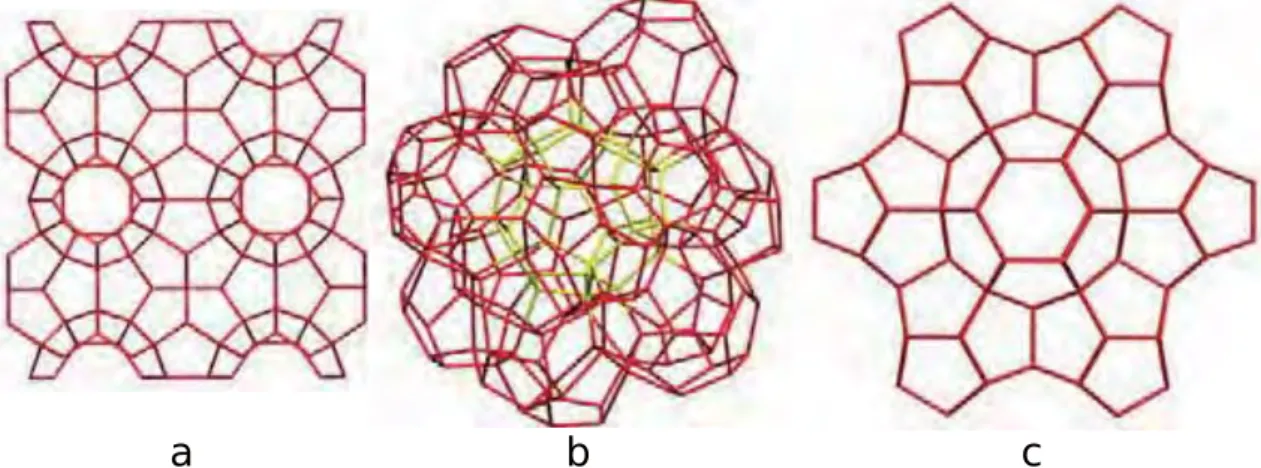
There are three known structure types for clathrate hydrates, namely sI, sII and hexag- onal known as sH. The two first mentioned have the cubic crystalline structure of Pm3n and Fd3m, respectively, while the last has hexagonal based structure. CO2 and CH4
hydrates have sI structure, O2 and N2 have sII and some solid-phase materials found in slurry reservoir fluids are suggested to have sH structure coexist with sII [56].
a b c
Fig. 2.1.Clathrate hydrate structure of (a) sI, (b) sII and (c) sH.
The unit cell of sI containing 46 water molecules in a unit cell. Each unit cell then tiled to form 3 dimensional structure of small-pentagonal-dodecahedron cages (512) and large- tetradecahedron cages which are hexagonal truncated trapezohedron (51262). The two type of enclosures are arranged to show WeairePhelan structure with open tetrahedral O-O-O connection to deviate about 3.7◦. The average distance between oxygen-water atoms is 2.793 ˚A. Meanwhile, a lot more water molecules in a unit cell are needed to form the sII structure; here, a unit cell is containing 136 water molecules with the O-O average distance is 2.790 ˚A.
Unit cells are tiled to form sixteen similar small-pentagonal-dodecahedron (512) cor- respondingly as sI. Meanwhile, the arrangement also gives eight large hexahedra (51264) cages in which 3◦angle deviation of tetrahedrally connected oxygen water to its adjacent neighbor is shown. Three types of enclosures with the composition of three small 512 cages, two small 435663 cages and one large 51268 cage are arranged in which 34 water molecules are found in a unit cell to give sH structure. As previously mentioned, the large cage in this hexagonal structure can be filled by large molecules such as butane and hydrocarbon. The most stable structures are shown by sI and II.
Continues discovery of clathrate hydrates revealed more structure variants in which some would relate to Frank-Kasper (FK) structure [57]. The first variant is clathrate with tetragonal s-T structure. This structure has 12 water molecules in a unit cell arranged to make cells of 425864 cavities [58]. The second is clathrate materials having cavities such as 6×512, 4×51262 and 4×51263. There are 80 water molecules are found in a unit cell. This structure also known as the tetragonal s-K structure and can be found in Bromine hydrate [59]. The third variant to relate with FK structure is cubic s-III clathrate hydrate [60]. The structure have 2×4126886 and 6×4882 cavities built from
water molecules arrangements; here, a unit cell have 48 water molecules.
Fig. 2.2.Clathrate hydrate structure of tetragonal (a) s - T [58], (b) s - K [59] and (c) s - III [60]. Green spheres indicates guest molecules.
2.3 Filled Ices
Molecular hydrogen can form clathrate hydrate through single and multiple occupancies to fit in each cavity. Under high pressure, this small guest molecules can be occupied in different host arrangements rather than known clathrate hydrate structures; here, the structure mostly known as filled ice. The composition of this hydrogen hydrate material under 400 MPa pressure and 280 K temperature is (H2O)2H2 where ice structure frame- work observed as host. Filled ice from different guest inclusion can also be constructed by compressing clathrate hydrate. For instance, CO2-filled ice is originated from sI CO2 clathrate hydrate [61]. Meanwhile, filled ice where ice-XVII is host framework can be observed by compressing sII CO2 clathrate structure [62]. Detailed schematic diagram regarding this phase transition concerning pressure at room temperature was presented in [63].
There are several filled ice structures extensively studied, namely C1 hydrate which has ice II host structure to encapsulate H2 and C2 hydrate system occupying the same small-sized hydrogen gas in lattice site of ice Ic water framework [23]. These two have H2: H2O stoichiometry of 1:6 for C1 while 1:1 shown by C2 to be considered as a hydrogen- rich compound. In the case of C2 system, pressure dependence revealed larger than the unoccupied would show under the same pressure condition; similar behavior affected on νOH frequency and dOH distance of unfilled ice Ic structure would be under the twice higher pressure condition [25]. Meanwhile, since H2+ H2O is a binary system, C1and C2
were found to coexist under pressure condition ranged from 2.3 GPa to 3.1 GPa.
Furthermore, MH-III structure hosting methane was found at about 2 GPa in which water molecules are arranged very similar to hexagonal ice structure [64]; this methane- water compound is considered as the first methane guest encapsulated in hydrate structure known as filled ice. Similar to hexagonal ice, hydrogen bond arrangements revealed in
this hydrate are reasonably disordered in Imcm space group, where a = 4.7458(5) ˚A, b
= 8.0644(9) ˚A andc= 7.8453(7) ˚A. The methane-guest shows strong repulsion character with regards to the C-O distances and showed increases strongly with pressure when the system at 11 GPa. This repulsive character already observed at 3.0 GPa with interaction energy in the order of 1 kJ/mol [65].
Fig. 2.3.MH-III structure [64].
Another structure, namely C0 was recently discovered. However, the definite structure of this C0 hydrate system had not been established. Previous observation at 80 K and 0.5 GPa pressure employing ex-situ X-ray diffraction proposed structure of space group P3112 (or P3121) in which water molecules presence in sites 3a2 with half occupancy [66].
However, this spiral H-bond network of trigonal arrangements showed a violation of ice rules. Subsequently, Strobel et al. [67] continues the effort to observe properly the C0 structure utilizing XRD suggesting two structures, tetragonal S-T structure andα - and β - quartz arrangements. Next, Smirnov et al. [68] revealed that the partially occupied sites were N2 molecules included during recovery while H2 occupying the channel; this configuration is later known as C0-II. The result also indicates that this C0have tetragonal S-T structure. Recent XRD study revealed that the C0 have structure closely similar to Smirnov et al. [68] with hexagonal symmetry [69]. Recent findings stated that at 100- 270 K and pressures range from 360 MPa to 700 MPa [70], C0 have stability region at the sII clathrate and C1 based ice II structure. The results revealed hexagonal symmetry with spacegroup of P6122 when this unoccupied C0system recovered to ambient pressure;
this new form of hexagonal ice structure named as ice XVII. Proton-ordering and guest occupancies later determined by in-situ neutron and X-ray diffraction. Along with CO2 hydrate-II, H2 hydrate of C0 show similar structure of chiral and has large open spiral channels for the guest to move [61] freely. This P6122 spacegroup have a = 6.2763(5) ˚A and c= 6.1875(19) ˚A with density of 0.991 g/cm3, exhibits new features of hydrate and hydrogen bonded was suggested disordered.
Fig. 2.4.Filled ice structure of (a) C0 [61] (b) C1 and (c) C2. Red and Green spheres indicate oxygen atoms and guest molecules, respectively. Grey line describes hydrogen bond connecting water frameworks. C1 and C2 systems are redraw with ice configurations taken from Buch et al. [71] while guest molecules are included without energy minimization. Both structures are viewed along hexag- onal puckered-plane
Chapter 3
Molecular Dynamics Calculation
Molecular dynamics (MD) calculation were performed to theoretically study hydrogen hydrate of filled ice II (C1) and Ic (C2). Long-time calculation of 100 ns was needed, in particular, to investigate the hydrogen molecules diffusion, in the full occupation setup.
Meanwhile, 50 ns were performed for the one vacancy setup. MD calculations were done by using LAMMPS package [72]. The usage starts from energy minimization to the produc- tion run. The simulated system was conditioned to reproduce the previous experimental setups. In this condition, fast diffusion of hydrogen guest molecules is observed. The rapid diffusion of the guest showed less influenced by the applied high pressure within a certain range.
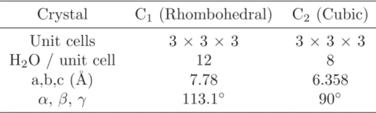
When simulating hydrate C1 system, 1 GPa of pressure and 291 K of temperature were controlled during equilibration and production run. The frozen-water molecules framework has R¯3 space group structure taken from Busch et al. [71] satisfying Bernal- Fowler rules [42]. The structure has rhombohedral unit cell with lattice parameter a=
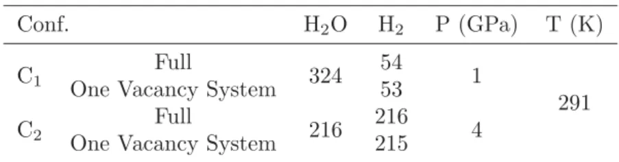
7.78 ˚A while α, β, and γ is 113.1 ◦ containing 12 water molecules. Meanwhile, the calculation was performed with 3 × 3 × 3 unit cells containing 324 water molecules and encapsulating 54 hydrogen guest molecules. Initially, the guest was placed in the lattice site. The H2: H2O stoichiometry was following previous experimental results of Vos et al. [23] for full occupation. Imperfect synthesized result by giving one lattice site unoccupied was prepared to study occupation defect-driven diffusion; here, this setup was named as one vacancy system. These two distinctive confinement setups were then
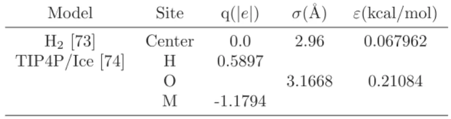
Table 3.1.The potential parameter for water and hydrogen guest molecules used in MD calculation. For H2 guest molecule, both LJ and charge site are located at the same center of mass. Meanwhile, Oxygen atom’s position of water molecule is used as LJ calculation point while the negative charge placed at M position, located between the center of H-H and Oxygen.
Model Site q(|e|) σ(˚A) ε(kcal/mol)
H2 [73] Center 0.0 2.96 0.067962
TIP4P/Ice [74] H 0.5897
O 3.1668 0.21084
M -1.1794
Table 3.2.Host Framework Setup
Crystal C1(Rhombohedral) C2 (Cubic)
Unit cells 3× 3×3 3 ×3 ×3
H2O / unit cell 12 8
a,b,c (˚A) 7.78 6.358
α,β,γ 113.1◦ 90◦
entering energy minimization employing conjugate gradient methods. During this process, the water molecules and guest’s position were corrected concerning their pair-interaction to achieve minimum energy arrangements. The observed cavity volume was fluctuated slightly associating to the guest occupation. The resulted arrangements were then entering equilibration stage under the thermodynamic conditions previously described. During equilibration run of 50 ps, energy conservation and thermodynamic fluctuations were carefully observed. Finally, after the completion of the previous stage, production run was performed in which 100 ns for full occupation setup. Although longer calculation was performed, no inter-site diffusion was achieved in full occupation system eventually.
Meanwhile, 50 ns was utilized on one vacancy system; here, many inter-site translations performed by hydrogen molecules are already observed.
In a closely similar treatment, calculation of hydrate C2 system adopted the same reference of the experimental result as hydrate C1, in which 4 GPa of pressure and 291 K of temperature. With regards to the arrangement, ice Ic structure was also taken from Buch et al. [71]. The unit cell is cubic with lattice parametera=7.78 ˚A composed of eight water molecules. When performing the calculation, ice Ic structure of 3×3×3 unit cells containing 216 water molecules were used as the host to encapsulate 54 H2 molecules.
One vacancy setup also employed in this hydrate with the similar purpose as filled ice II.
The guest positions were corrected during minimization process along with lattice site of water molecules framework. Minimization, equilibration and production calculations also treated in the same manner as hydrate C1.
During calculation of all setups and hydrates, thermodynamics conditions were con- trolled by using LAMMPS fix npt styles. This fix styles uses Verlet and rRESPA time integrators [75] on Nos`e-Hoover [76, 77] form of Shinoda et al. [78] equation of motion.
The schemes combined the hydrostatic equations [79] with the strain energy [80]. The desired temperature and pressure were highly preserved by implementing Nos´e- Hoover chain method. A chain of 4 thermostats was coupled to the system particles, while the other four to the barostat variables. All of the previously mentioned algorithms will be described further in the appendix.
Meanwhile, to simulate the intermolecular interaction, the sum of Lennard-Jones (LJ) pair potentials and the Coulomb defined by
φ=
i,j
4εij
σij
rij
12
−σij
rij
6
+ qiqje2 rij
, (3.1)
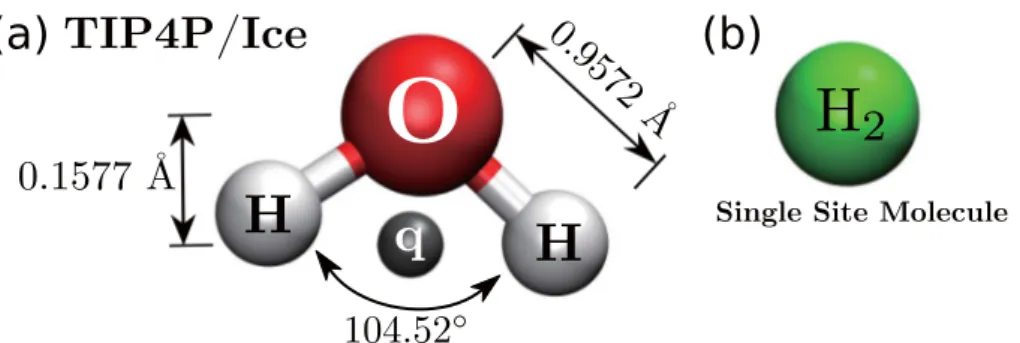
Fig. 3.1.Molecule model for (a) water framework, and (b) guest molecule
was used. To calculate the electrostatic interaction energy contribution, long-range Coulomb interaction was evaluated by using a particle-particle particle-mesh Ewald method [81] method with tail correction on LJ pair potential. The cut-off radius of 10
˚A was used for the pair energy interaction. To describe the guest molecules, one site H2 model was used. The model was proposed by [73] which shows the superfluidity of LJ (12,6) in finite-sized ultracold H2 bosonic clusters. To model host-water framework, TIP4P/Ice [74] was used. This water model is suitable to be used in solid-phase compound calculation with better reckoning ice properties compared to the TIP4P. To make the water model rigid, SHAKE algorithm [82] was used in preserving covalent bond between Oxygen and Hydrogen atom of water molecules to a distance at 0.9572 ˚A;
here, angle was also preserve to 104.52◦. Further discussion of the previously mentioned method are presented in the appendix.
When calculating pair-potential energy with equation 3.1, parameters that were used are listed in 3.1. Meanwhile, the parameter of intermolecular interaction between water and hydrogen guest molecules was calculated by using Lorentz-Berthelot [83, 84] combination rules, written by:
σ12 = σ1+σ2
2 (3.2)
ε12 =√
ε1ε2 . (3.3)
A single site of hydrogen guest molecules was used during the calculation of all systems.
The potential parameters were taken from Sevryuk et al. [73] Details of this system’s setup are listed in table 3.2. For the details of thermodynamic condition, table 3.3 collected the value used in the calculation along with guest setup information on every simulated system. When performing minimization, 1×10⁻²⁵ of relative energy differences was used as the stopping criteria between the consecutive iteration. Meanwhile, in the equilibrium and production run, thermostat and barostat were implemented with 0.1 ps and 1.0 ps of relaxation time respectively. Time step of 1 fs is used for the production run for all simulated systems while for the van der Waals cut off radius is 10.0 ˚A. Periodic boundary condition was used on each simulated systems to overcome the surface effect. In appendix A, a scheme to handle periodic boundary condition is explained since non-orthogonal box
Table 3.3.Hydrogen molecules and NPT Condition
Conf. H2O H2 P (GPa) T (K)
C1 Full
324 54
1 One Vacancy System 53 291
C2 Full
216 216 One Vacancy System 215 4
setup was used when simulating hydrogen hydrate C1 system. The scheme can be used for both orthogonal and non-orthogonal axis system.
To calculate the diffusion coefficient, the following equation
|Δr(t)|2= 2nDt, (3.4)
was used where|Δr(t)|2is the mean square displacement of all hydrogen guest molecules, D is diffusion coefficient, n is dimensionality and t is correlation time. In this present study, n equal to 3 was used for all diffusion coefficient calculation. When calculating diffusion coefficient in one vacancy systems, 50 ns of calculation trajectory data was used for 2 ns of correlation time. When calculating this property, a trajectory of hydrogen molecules contributed to the guest diffusion coefficient were secluded from other molecule exist in the system. Periodic boundary condition was employed closely followed the scheme listed in Appendix A. Linear regression was performed to calculate tangent of the plot of mean square displacement. As can be seen from Fig. 3.2 (a), the arrangement of water molecules in hydrate C1 and C2 consist of lattice sites assembled in such a way to have different neighboring distance concerning the crystallographic structure. In the case of hydrate C1, the nearest separation along optical c axis is three times shorter compared to the separation along the basal plane. The remarkable difference in adjacent hydrogen molecules between the two crystallographic axes suggested the highly anisotropic diffusion would occur in this hydrate. Therefore, only hydrogen molecules located along a column of optical axis direction were used in diffusion coefficient calculation. In the case of hydrate C2, hydrogen molecules are arranged to be tetrahedrally connected. This arrangement is similar to the tetrahedrally connected water molecules in which forming hexagonal puckered-plane. In a similar manner to the arrangement of oxygen atom in the water molecule’s framework, hydrogen molecules positioned at a vertex of a hexagonal ring where the distance between adjacent vertices is equal. Within this structure, all of the hydrogen molecules are therefore used in the calculation of diffusion coefficient. The neighbor list was updated every 1 calculation step with extra distance beyond force cutoff was 2 ˚A. In this calculation, a neighbor-list build can be performed if some atom traveled a distance of more than half of its neighbor’s skin value at the last build.
(a)
(b)
Fig. 3.2.The arrangement of oxygen atoms (red spheres) and H2 molecules (green spheres) in (a) hydrate C1 and (b) C2. Hydrate C1 is viewed parallel to the basal plane and C2on (110) plane. Bond connecting the adjacent oxygen atoms and hydrogen molecules are drawn to clarify the structural configuration with the distance criteria 3.0 ˚A for hydrate C1 and 2.8 ˚A for C2.
Chapter 4
Results and Discussion
4.1 Equilibrium Condition
First of all, evaluation of equilibrium condition from all of the simulated systems is pre- sented. When doing this evaluation, the following analysis will further describe controlled thermodynamic, and energy resulted from MD calculation concerning calculation-time.
The analysis was taken in the production-run stage of the two different calculation time.
For time-series plot of total and potential energy, the result will indicate whether the calculation is in the equilibrium state or necessarily need more equilibration time. Mean- while, for the controlled thermodynamic properties such as temperature and pressure, the plot will mainly describe whether the average value coincide with the desired condition properly or the contrary. The evaluation will be presented on every simulated system, namely C1 of full occupation and one vacancy systems, and C2 system with two similar setups of lattice site’s occupation as in the C1. Plot of controlled thermodynamics and energy are given in Figs. 4.1 to 4.4. As can be seen in all figures, both temperature and pressure fluctuate during calculation time. The fluctuation is observed to indicate the real physical features normally occurred in the canonical system; here, the temperature is not a well defined variable even in the segregated system [85]. Also, the fluctuation is evidence since system’s temperature is defined by thermostat temperature; here, the fluctuation is a common behavior in the interaction of heat-bath and the system’s particle.
In the case of pressure, this variable is generally the most thermodynamic condition to fluctuate. However, their average value shows constantly coincide with the desired value to achieve. During this production run, the feature is observed with an acceptable range of instantaneous value of fluctuation. Accordingly, it is safe to state that the calculation is under the condition similar to the experimental setup [33] and [34].
Meanwhile, average energy plot in this system shows constant value concerning the calculation time. Fluctuation is also evidence since the total energy and the temperature are related by [86–88] :
ΔEΔt=kBTo2 (4.1)
-4200 -4150 -4100 -4050 -4000
0 2×10⁷ 4×10⁷ 6×10⁷ 8×10⁷
Et (kcal/mol)
time (fs) -4200
-4150 -4100 -4050 -4000
0 2×10⁷ 4×10⁷ 6×10⁷ 8×10⁷
(a)
6000 8000 10000 12000 14000
0 2×10⁷ 4×10⁷ 6×10⁷ 8×10⁷
P (atm)
time (fs) 6000
8000 10000 12000 14000
0 2×10⁷ 4×10⁷ 6×10⁷ 8×10⁷
(b)
255 270 285 300 315 330
0 2×10⁷ 4×10⁷ 6×10⁷ 8×10⁷
T (K)
time (fs) 255
270 285 300 315 330
0 2×10⁷ 4×10⁷ 6×10⁷ 8×10⁷
(c)
-4800 -4770 -4740 -4710 -4680 -4650 -4620 -4590
0 2×10⁷ 4×10⁷ 6×10⁷ 8×10⁷
Ep (kcal/mol)
time (fs) -4800
-4770 -4740 -4710 -4680 -4650 -4620 -4590
0 2×10⁷ 4×10⁷ 6×10⁷ 8×10⁷
(d)
Fig. 4.1.Time series plot of Molecular dynamics calculation result on (a) total energy, (b) pressure, (c) temperature, (d) and potential energy C1 full occupation system during 3 ns of production run. Grey line indicates instantaneous value while blue line for average.
where ΔE=E−E0 and E0 is energy of system in equilibrium condition.
4.1.1 Filled ice II (C
1)
In hydrate C1system, average value of total and potential energy are depicted in Figs. 4.1a and 4.1d for full occupation, and Figs. 4.2a and 4.2a for the one vacancy. Plateau is shown on all plots of average energy value. These plots give evidence that the simulated system already in the equilibrium state and justifying the correct dynamic properties would have resulted from the production run. For the total energy, the constant value coexists at -4093(6) kcal/mol on full occupation, while -4093(4) kcal/mol coexist on one vacancy.
Total potential energy is calculated to be -4700(2) kcal/mol for full occupation, while -4700(4) kcal/mol for one vacancy. The energy value is calculated from all molecular interactions to exist in the system. In the meantime, fluctuations are evidence showing regular physical feature acquired in most MD calculations. The total energy fluctuates between -4125 kcal/mol and -4000 kcal/mol for full occupation. Meanwhile, the total energy value varying from -4180 kcal/mol to -4030 kcal/mol in one vacancy setup. In the case of potential energy, fluctuation between -4750 kcal/ mol and -4640 kcal/mol observed in full occupation, while a similar range of values shown by one vacancy.
![Fig. 2.2. Clathrate hydrate structure of tetragonal (a) s - T [58], (b) s - K [59] and (c) s - III [60]](https://thumb-ap.123doks.com/thumbv2/123deta/5639681.2003215/22.892.153.763.215.445/fig-clathrate-hydrate-structure-tetragonal-t-k-iii.webp)
![Fig. 2.3. MH-III structure [64].](https://thumb-ap.123doks.com/thumbv2/123deta/5639681.2003215/23.892.299.602.315.530/fig-mh-iii-structure.webp)
![Fig. 2.4. Filled ice structure of (a) C 0 [61] (b) C 1 and (c) C 2 . Red and Green spheres indicate oxygen atoms and guest molecules, respectively](https://thumb-ap.123doks.com/thumbv2/123deta/5639681.2003215/24.892.191.704.162.401/filled-structure-green-spheres-indicate-oxygen-molecules-respectively.webp)