LMH1983 オーディオ・クロック付き
3G/HD/SDビデオ・クロック・ジェネレータ
特 長
●
A/Vクロックを同時に生成する4つのPLL
− PLL1:27MHzまたは13.5MHz
− PLL2:148.5MHzまたは74.25MHz
− PLL3:148.5/1.001MHzまたは74.25/1.001MHz
− PLL4:98.304MHz / 2
X(X = 0~15)
●
3×2ビデオ・クロック用クロスポイント
●
ジッタ特性とロック時間を最適化できる柔軟なPLL
帯域幅設定
●
新しいリファレンスへのなめらかな再同期
●
リファレンス喪失時、デジタル・ホールドオーバー
またはフリーラン動作
●
リファレンス喪失やPLLロック喪失を示すステータ
ス・フラグ
●
3.3V単一電源動作
●
アドレス選択ピンを備えたI
2Cインターフェイス
(3値入力)
アプリケーション
●
トリプル・レート(3G/HD/SD) SDI SerDes
●
FPGAのリファレンス・クロックの生成/クリーニング
●
オーディオの埋め込み・抽出機器
●
ビデオ・カメラ
●
フレーム・シンクロナイザ(Genlock、DARS)
●
A/D、D/A変換/編集/処理カード
●
キーヤーおよびロゴ・インサータ
●
フォーマット/規格コンバータ
●
ビデオ・ディスプレイおよびプロジェクタ
●
A/V用試験装置および測定機器
概 要
LMH1983は、業務用放送機器のための多くの機能を集積し
たプログラマブル・オーディオ/ビデオ(A/V)クロック・ジェネ
レータです。全米映画テレビジョン技術者協会(SMPTE)が定
めたシリアル・デジタル・インターフェイス
(SDI)ビデオ規格や
JAJSBT3参考資料
LMH1983
www.tij.co.jp LOOP FILTER 27 MHz VCXOLMH1983
FPGA
A/V Frame Sync with Downconverter, Audio Embedder and
1080p/59.94 SDI out + embedded audio LMH1981 Sync Separator H sync V sync 525i Analog ref. in F sync 27 MHz (PLL1) 148.5 MHz (PLL2) 148.35 MHz (PLL3)
525i/29.97 SDI out + embedded audio CLKout1 CLKout2 CLKout3 Hin Vin Fin 29.97 Hz (TOF1) 29.97 Hz (TOF2)
代表的なアプリケーション ‒ A/Vフレーム・シンクロナイザ用ビデオGenlockタイミング生成
静電気放電対策
これらのデバイスは、限定的なESD(静電破壊)保護機能を内
蔵しています。保存時または取り扱い時に、MOSゲートに対す
る静電破壊を防止するために、リード線どうしを短絡しておく
か、デバイスを導電性のフォームに入れる必要があります。
3x2 Video Clock Crosspoint External Loop Filter and VCXOVC_LPF XOin- CLKout2-NO_LOCK Fin Hin Vin SDA SCL CLKout2+ CLKout1+ CLKout3-CLKout3+ CLKout1-Device Control and Registers ADDR XOin+ = Device pins NO_REF 27.0 (13.5) MHz VDD/2 PLL3 3G(HD)/1.001 Video Clock PLL2 3G(HD) Video Clock I2C Interface PLL1 Genlock PLL 27 MHz VCXO 148.5 (74.25) MHz 148.35, (74.176) MHz In1 In2 In3 Out2 Out3 Vc(Genlock) Vc(Freerun) 10-Bit SAR ADC Input Format and Polarity Detection DAC Ref Fbk NO_ALIGN TOF1 Fout1 Fout2 Fout3
機能ブロック図
れている数々のフェーズ・ロック・ループ(PLL)や電圧制御水
晶発振器(VCXO)を本製品で置き換えることができます。ク
ロック・クリーニング回路を追加しなくとも、どのようなSDI
トランスミッタでも、その厳格な出力ジッタ仕様を満たす、低
ジッタのリファレンス・クロックを供給します。
LMH1983は、自動入力フォーマット検出、簡単にプログ
ラム可能なマルチA/V出力フォーマット、Genlockまたはデ
ジタル・フリーラン・モード、各種自動機能をオーバーライト
できるプログラミング機能を備えています。認識可能な入力
フォーマットには、主要なビデオ規格のHVF同期信号のほか、
27MHz、10MHz、並びに32/44.1/48/96kHzのオーディオ・ワー
ド・クロックなどがあります。
2ステージPLLアーキテクチャは、4個のPLLと3個のオン
チップVCOを集積しています。第1ステージ(PLL1)は、ループ
帯域幅が狭い、外付けの低ノイズ27MHz VCXOを使用して、ク
リーンなリファレンス・クロックを次のステージに供給します。
第2ステージ(PLL2、3、4)は、148.5MHz、148.5/1.001MHz、
98.304MHz (24.576MHz × 4)など、主要な基本デジタルA/Vク
ロック・レートを同時生成する3個の並列VCO PLLで構成され
示すタイミング・パルスを生成できます。
リファレンスにロックした時は、内蔵の10ビットA/Dコン
バータ(ADC)がループ・フィルタ制御電圧に追従します。リ
ファレンス喪失(LOR)が発生した場合には、制御電圧を保持
して、出力精度を直前のリファレンスの
±0.5ppm(typ)以内に保
つようプログラムすることもできます。LMH1983を、グリッ
チを出すことなく直前のリファレンスに再同期させることもで
きます。
LMH1983は、省スペースの6mm × 6mm 40ピンLLPパッケー
ジで供給されます。
ピン説明
Pin No.
Pin Name
I/O
Signal Level
Pin Description
–
DAP
–
GND
Die Attach Pad (Connect to ground on PCB)
1
VDD
–
Power
3.3V supply for PLL1
2
VDD
–
Power
3.3V supply for logic I/O
3
Hin
I
LVCMOS
Horizontal sync reference signal
Auto polarity correction for HVF will be based off Hin polarity.
Recognized clock inputs can be applied to Hin.
4
Vin
I
LVCMOS
Vertical sync reference signal
5
Fin
I
LVCMOS
Field sync (odd/even) reference signal
6
INIT
I
LVCMOS
Reset signal for audio-video phase alignment (rising edge triggered)
7
ADDR
I
LVCMOS
I
2C address select
Pin settings:
ピン配置図
1 2 3 4 5 6 7 8 30 29 28 27 26 25 24 23 33 34 35 36 37 38 39 40 VDD Vin Fin VC_LPF CLKout3+ CLKout 4-XOin -Cbyp2 VDD Hin NO_LOCK INIT Fout1 GND NO_ ALIGN GND Fout2 CLKout2+ SDA CLKout3-CLKout4+ 9 SCL 10 22 21 Fout3 31 32 11 12 13 14 15 16 17 18 19 20 VDD Fout4 (OSC in) VDD VDD Cbyp3 CLKout2-VDD CLKout1-CLKout1+Die Attach Pad (DAP) Connect to GND on PCB ADDR GND Cbyp4 VDD XOin + VDD VDD NO_REF
40-Pin WQFN (Top View)
Package Number RTA0040A
Pin No.
Pin Name
I/O
Signal Level
12
NO_ALIGN
O
LVCMOS
Loss of alignment status flag for OUTs 1–4 (active high)
13
NO_REF
O
LVCMOS
Loss of reference status flag (active high)
14
CLKout4–
O
LVDS
Audio clock from PLL4 (fundamental rate is 98.304 MHz).
15
CLKout4+
The output is 24.576 MHz by default and is selectable via the host.
16
VDD
–
Power
3.3V supply for CLKout4
17
Fout4 (OSCin)
I/O
LVCMOS
Audio frame timing signal for OUT4 (active low.) Timing Generator fixed to PLL4
clock. The output is the audio-video-frame (AVF) pulse by default and is
programmable via the host. Optional OSCin function can be used to apply a 27
MHz external clock for PLL4 to generate an audio clock independent of the video
input reference; this function must be enabled via the host.
18
GND
–
GND
Ground
19
VDD
–
Power
3.3V supply for PLL3 and PLL4
20
VDD
–
Power
3.3V supply for CLKout3
21
GND
–
GND
Ground
22
Fout3
O
LVCMOS
Video frame timing signal for OUT3 (active low).
23
CLKout3+
O
LVDS
Video clock from PLL1, PLL2, or PLL3 depending on output crosspoint mode. The
24
CLKout3–
output is 148.35 MHz by default and is selectable via the host.
25
Cbyp3
–
Analog
Bias bypass for on-chip LDO for PLL3
Connect to 1.0 uF and 0.1 uF bypass capacitors.
26
Cbyp4
–
Analog
Bias bypass for on-chip LDO for PLL4
Connect to 1.0 uF and 0.1 uF bypass capacitors.
27
Cbyp2
–
Analog
Bias bypass for on-chip LDO for PLL2
Connect to 1.0 uF and 0.1 uF bypass capacitors.
28
CLKout2+
O
LVDS
Video clock from PLL1, PLL2, or PLL3 depending on output crosspoint mode. The
29
CLKout2–
output is 148.5 MHz by default and is selectable via the host.
30
Fout2
O
LVCMOS
Video frame timing signal for OUT2 (active low).
31
VDD
–
Power
3.3V supply for CLKout2
32
VDD
–
Power
3.3V supply for PLL2
33
XOin–
(3)I
LVCMOS/LV 27 MHz VCXO clock signal for PLL1.
34
XOin+
DS
– LVCMOS: Directly connect clock signal to XOin+ and bias XOin- to mid-supply
with 0.1uF bypass capacitor.
– LVDS: Directly connect LVDS clock signals to XOin+ and XOin-.
Note: A TCXO or other clean 27 MHz oscillator can be applied for standalone
clock generation using PLLs 2-4 (bypass PLL1).
35
CLKout1–
O
LVDS
Video clock from PLL1.
36
CLKout1+
The output is 27 MHz by default and is selectable via the host.
37
Fout1
O
LVCMOS
Reference frame timing signal for OUT1 (active Low). Timing generator fixed to
PLL1 OUT1 Format follows the reference input format.
38
VDD
–
Power
3.3V supply for CLKout1
39
GND
–
GND
Ground
40
VC_LPF
O
Analog
Loop filter for PLL1 charge pump output with VCXO Voltage Control (VC) sensing.
If free-run and holdover mode, PLL1 is disabled and an internal DAC outputs a
control voltage to the VCXO.
(3)XOin must be driven by a 27 MHz clock in order to read or write registers via I2C.
絶対最大定格
(1)If Military/Aerospace specified devices are required, contact the Texas Instruments Sales Office/Distributors for
availability and specifications.
ESD耐圧
(2)人体モデル
2500V
マシン・モデル
250V
帯電デバイスモデル
750V
電源電圧(V
DD)
3.6V
入力電圧(各入力)
−0.3V
∼
V
DD+0.3V
出力電圧(各出力)
−0.3V
∼
V
DD+0.3V
保存温度範囲
−65°C
∼
+150°C
接合部温度(T
JMAX)
150°C
熱抵抗(θ
JA)
33°C/W
ハンダ付け情報 www.ti.com/product/lmh1983の製品フォルダとwww.ti.com/lit/an/snoa549c/snoa549c.pdfを参照してください。
(1) 絶対最大定格とは、この値を超えるとデバイスが破損する可能性のあるリミット値です。動作定格はデバイスが機能する条件を示します。 保証された仕様および試験条件については「電気的特性」を参照してください。(2) 人体モデル適用規格: MIL-STD-883、Method 3015.7。マシン・モデル適用規格: JESD22-A115-A (JEDECのESD MM規格)。 電界誘導帯電デバイスモデル適用規格: JESD22-C101-C (JEDECのESD FICDM規格)。
推奨動作条件
V
DD3.3V ± 5%
入力電圧
0V
∼
V
DD温度範囲(T
A)
–40°C
∼
85°C
電気的特性
特記のない限り、すべてのリミット値はT
A= 25℃、V
DD= 3.3V、R
L_CLK= 100Ω(CLKout差動負荷)で保証されます。
太字のリミット値は、全温度範囲に対して適用されます。
Symbol Parameter Conditions Min(3) Typ(4) Max(3) Units
Default register settings, no load on logic outputs. VDD=
IDD Total Supply Current 3.465V 170 212 mA
PLL2, PLL3 and PLL4 disabled, no load on logic outputs.
IDD Total Supply Current VDD= 3.465V 60 100 mA
Reference Inputs (Hin, Vin, Fin)
VIL Low Input Voltage IIN= ±10 μA 0 0.3 VDD V
VIH High Input Voltage IIN= ±10 μA 0.7 VDD VDD V
Time from when reference input first presented to when input
TAFD Auto-Format Detection Time detected as indicated by NO_REF going low. Reference 2 4 frames timing must be stable and accurate (no missing pulses).
OSCin Logic Inputs
VIL Low Input Voltage IIN= ±10 μA 0 0.3 VDD V
VIH High Input Voltage IIN= ±10 μA 0.7 VDD VDD V
I2C Interface (SDA, SCL)
VIL Low Input Voltage 0 0.3 VDD V
VIH High Input Voltage 0.7 VDD VDD V
IIN Input Current VINbetween 0.1 VDDand 0.9 VDD −10 +10 μA
電気的特性
特記のない限り、すべてのリミット値はT
A= 25℃、V
DD= 3.3V、R
L_CLK= 100Ω(CLKout差動負荷)で保証されます。
太字のリミット値は、全温度範囲に対して適用されます。
(1)(2)
Symbol Conditions Min(3) Typ(4) Max(3)
Status Flag Outputs (NO_REF, NO_ALIGN,NO_LOCK)
VOL Low Output Voltage IOUT= +10 mA 0.4 V
VOH High Output Voltage IOUT= −10 mA VDD−0.4V V
Frame Timing Outputs
VOL Low Output Voltage IOUT= +10mA, Fout1, Fout2, Fout3(5) 0.4 V
VOH High Output Voltage IOUT= –10mA Fout1, Fout2, Fout3(5) VDD-0.4V V
Output buffer shutdown, pin connected to VDDor GND
IOZ Output Shutdown Leakage Current V 0.4 10 |μA|
DD= 3.465V
tR Rise Time 20% to 80% 15 pF Load 1 ns
tF Fall Time 20% to 80% 15 pF load 1 ns
TOF1 delay measured from the CLKout1 clock reset edge.
tD1(6) Timing output delay time Delay spec applies for all output clock and format supported 22 ns by the output pair following output initialization. 15 pF load.
TOF2 delay measured from the CLKout2 clock reset edge.
tD2 Timing output delay time Delay spec applies for all output clock and format supported 2 ns by the output pair following output initialization. 15 pF load.
TOF3 delay measured from the CLKout3 clock reset edge.
tD3 Timing output delay time Delay spec applies for all output clock and format supported 2 ns by the output pair following output initialization. 15 pF load.
TOF4 delay measured from the CLKout4 clock reset edge.
tD4 Timing output delay time Delay spec applies for all output clock and format supported 22 ns by the output pair following output initialization. 15 pF load.
Video and Audio Clock Outputs (CLKout1, CLKout2 and CLKout3)
Measured at CLKout1 all other CLKouts shutdown 250
27 MHz TIE deterministic Jitter fs
Measured at CLKout1, other CLKouts output default PLL 250
Measured at CLKout2 all other CLKouts shutdown 8
148.5 MHz TIE deterministic Jitter ps
Measured at CLKout2, other CLKouts output default PLL 8
tDJ Measured at CLKout3 all other CLKouts shutdown 4
148.35 MHz TIE deterministic Jitter ps
Measured at CLKout3, other CLKouts output default PLL 4
Measured at CLKout4 all other CLKouts shutdown 15
24.576 MHz TIE deterministic Jitter ps
Measured at CLKout4, other CLKouts output default PLL 15
Measured at CLKout1, other CLKouts shutdown 2.7
27 MHz TIE random Output Jitter ps
(7)
Measured at CLKout1, other CLKouts output default PLL 2.7
Measured at CLKout2, other CLKouts shutdown 3.0
148.5 MHz TIE Random Output ps
Jitter(7) Measured at CLKout2, other CLKouts output default PLL 3.0
tRJ Measured at CLKout3, other CLKouts shutdown 3.5
148.35 MHz TIE Random Output ps
Jitter(7) Measured at CLKout3, other CLKouts output default PLL 3.5
Measured at CLKout4, other CLKouts shutdown 3.4
24.576 MHz TIE Random Output ps
Jitter(7) Measured at CLKout4, other CLKouts output default PLL 3.4
TD Duty Cycle Measured at 50% level of clock amplitude, any output clock 50 %
Rise Time
tR 20% to 80% 15 pF load 400 ps
Fall Time
tF 80% to 20% 15 pF load 400 ps
VOD Differential Signal Output Voltage 100Ω differential load, CLKout1, CLKout2 or CLKout3(8) 247 350 454 mV (5)FoutXのtDは、CLKoutの立ち上がりクロック・エッジからFoutXの立ち下がりエッジまでを50%レベルで測定されたものです。 (6)CLKoutXのtDは、XOinの立ち上がりクロック・エッジからCLKoutXの立ち上がりクロック・エッジの間において50%のレベルで測定されたものです。 測定は、入力クロックと出力クロックの位相が揃った時点のクロック・サイクルで行われています (7)SDおよびHDのクロック出力ジッタは、XOに20psピーク・ツー・ピークのジッタを含むクロックを入力し、タイム・インターバル・エラー(TIE)法による ジッタ測定で得られたものです。TIEピーク・ツー・ピーク・ジッタの代表値は、Tektronix DSA71604オシロスコープと1GHzアクティブ差動プローブ、 TDSJIT3ジッタ解析ソフトウェアを使用し、LMH1983評価ベンチ・ボード上で測定しました。TDSJIT3クロックTIE測定のセットアップ:10–12のビット 誤り率(BER)、100,000回以上のサンプルデータの取り込み。 Parameter Units
電気的特性
特記のない限り、すべてのリミット値はT
A= 25℃、V
DD= 3.3V、R
L_CLK= 100Ω(CLKout差動負荷)で保証されます。
太字のリミット値は、全温度範囲に対して適用されます。
(1)(2)
Symbol Conditions Min(3) Typ(4) Max(3)
VOS Common Signal Output Voltage 100Ω differential load, CLKout1, CLKout2 or CLKout3(8) 1.125 1.25 1.375 V
|Change to VOD| for
|VOD| Complementary Output States 100Ω differential load, CLKout1, CLKout2 or CLKout3(8) 50 |mV|
|Change to VOS| for
|VOS| Complementary Output States 100Ω differential load, CLKout1, CLKout2 or CLKout3(8) 50 |mV|
Differential clock output pins connected to GND for CLKout1,
IOS Output Short Circuit Current CLKout2 or CLKout3 24 |mA|
Output buffer in shutdown mode, differential clock output
IOZ Output Shutdown Leakage Current pins connected to VDDor GND 1 10 |µA| VCXO Input (XOin)
Maximum Relative Frequency
fOFF Offset between VCXO Input and H Assumes H input jitter of ±15 ns ±150 ppm
Input
Single-ended Signal Input Voltage
VXOin_SE Range Single-ended input buffer mode 0 VDD V
Differential Signal Input Voltage
VXOin_DIFF Range Differential input buffer mode, VCM= 1.2V 247 350 454 mV Digital Holdover and Free-Run Specifications
VVCout_RNG DAC Output Voltage Range Digital Free-run Mode 0.5 VDD-0.5V V
Parameter Units
サポートされている規格と
タイミング・フォーマット
表1に、サポートされている標準タイミング・フォーマットを
示します。この表には、LMH1983を各入出力フォーマットに
設定するためのパラメータも掲載されています。表1に掲載さ
れているフォーマットについては、入力の自動検出が対応可能
です。自動検出機能より優先させたければ、ホストからI
2C経由
で入力フォーマットを手動設定することもできます。
INPUT
TIMING
/PLL1
PARAMETERS
OUTPUT
TIMING
(OUT1
–4)
PARAMETERS
Reference
Feedback
Phase
Detector
PD
Periods
per
PLL
Clock
Freq.
Total
Clocks
per
Total
Lines
per
Frame
Rate
PLL#
Divider
Divider
(PD)
Freq.
(kHz)
Frame
Counter
(MHz)
Line
Counter
Frame
Counter
(Hz)
1
27.0
1716
1
1716
15.7343
525
525
29.97
2
148.5
9438
1
27.0
1728
1
1728
15.625
625
625
25
2
148.5
9504
1
27.0
858
1
858
31.4685
525
525
59.94
2
148.5
4719
1
27.0
864
1
864
31.25
625
625
50
2
148.5
4752
1
600
45.0
750
2
148.5
3300
750
60
5
3003
8.99101
150
3
148.35
3300
750
59.94
1
720
37.5
750
2
148.5
3960
750
50
1
1200
22.5
750
2
148.5
6600
750
30
5
6006
4.49550
150
3
148.35
6600
750
29.97
1
1440
18.75
750
2
148.5
7920
750
25
1
1500
18.0
750
2
148.5
8250
750
24
2
3003
8.99101
375
3
148.35
8250
750
23.98
1
400
67.5
1125
2
148.5
2200
1125
60
5
2002
13.48651
225
3
148.35
2200
1125
59.94
1
480
56.25
1125
2
148.5
2640
1125
50
1
800
33.75
1125
2
148.5
4400
1125
30
5
4004
6.74326
225
3
148.35
4400
1125
29.97
1
960
28.125
1125
2
148.5
5280
1125
25
1
1000
27.0
1125
2
148.5
5500
1125
24
1
1001
26.9730
1125
3
148.35
5500
1125
23.98
1
800
33.75
1125
2
148.5
4400
1125
30
5
4004
6.74326
225
3
148.35
4400
1125
29.97
1
960
28.125
1125
2
148.5
5280
1125
25
2
1125
24.0
1
4
98.304
2048
1
48000
4
1125
24.0
1
4
98.304
1024
1
96000
1000
1000
27.000
1
Input
only
clk
600
1620
16.6666
1
Input
only
Hsync Period
Interlaced (I) /
Format Code
Description
(in 27 MHz clocks)
Progressive (P)
0
480i/29.97
1716
I
1
576I25
1728
I
2
480P59.94
858
P
3
576P50
864
P
4
720P60
600
P
5
720P59.94
600.6
P
6
720P50
720
P
7
720P30
1200
P
8
720P27.97
1201.2
P
9
720P25
1440
P
10
720P24
1500
P
11
720P23.98
1501.5
P
12
1080P60
400
P
13
1080P59.94
400.4
P
14
1080P50
480
P
15
1080P30
800
P
16
1080P29.97
800.8
P
17
1080P25
960
P
18
1080P24
1000
P
19
1080P23.98
1001
P
20
1080I30
800
I
21
1080I29.97
800.8
I
22
1080I25
960
I
23
1080I24
1000
I
24
1080I23.98
1001
I
25
48 kHz Audio
562.5
—
26
96 kHz Audio
281.25
—
27
44.1 kHz Audio
612.244898
—
28
32 kHz Audio
843.75
—
29
27 MHz Hsync
1
—
30
10 MHz Hysnc
2.7
—
31
User Defined
User Defined
User Defined
63
Unknown
All Others
自動フォーマット検出コード
自動フォーマット検出コードは、レジスタ0x07(Output Mode
– PLL2 Format)、0x08(Output Mode – PLL3 Format)、0x20
(Input Format)に適用されます。
レジスタの説明
以下の表は、デバイス設定レジスタの詳細を示します。7ビット
以下のフィールドのデフォルト値は2進数で表され、8ビット
(1
バイト)のフィールドのデフォルト値は16進数で表されていま
す。予約済み(RSVD)フィールドには書き込みを行わないでく
ださい。
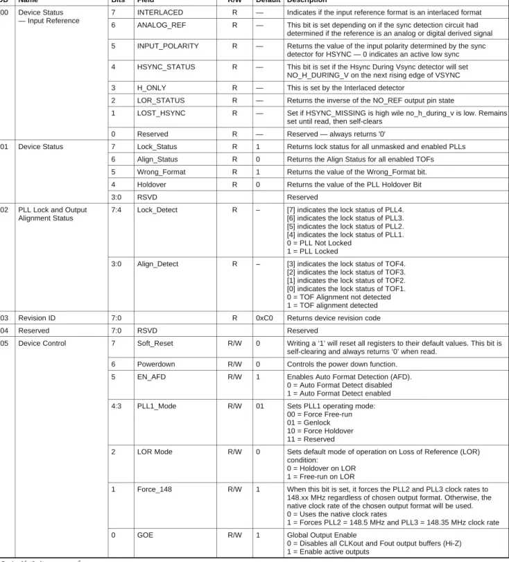
0x00 Device Status 7 INTERLACED R — Indicates if the input reference format is an interlaced format — Input Reference 6 ANALOG_REF R — This bit is set depending on if the sync detection circuit had
determined if the reference is an analog or digital derived signal 5 INPUT_POLARITY R — Returns the value of the input polarity determined by the sync
detector for HSYNC — 0 indicates an active low sync 4 HSYNC_STATUS R — This bit is set if the Hsync During Vsync detector will set
NO_H_DURING_V on the next rising edge of VSYNC
3 H_ONLY R — This is set by the Interlaced detector
2 LOR_STATUS R — Returns the inverse of the NO_REF output pin state
1 LOST_HSYNC R — Set if HSYNC_MISSING is high wile no_h_during_v is low. Remains set until read, then self-clears
0 Reserved R — Reserved — always returns '0'
0x01 Device Status 7 Lock_Status R 1 Returns lock status for all unmasked and enabled PLLs 6 Align_Status R 0 Returns the Align Status for all enabled TOFs 5 Wrong_Format R 1 Returns the value of the Wrong_Format bit.
4 Holdover R 0 Returns the value of the PLL Holdover Bit
3:0 RSVD Reserved
0x02 PLL Lock and Output 7:4 Lock_Detect R – [7] indicates the lock status of PLL4.
Alignment Status [6] indicates the lock status of PLL3.
[5] indicates the lock status of PLL2. [4] indicates the lock status of PLL1. 0 = PLL Not Locked
1 = PLL Locked
3:0 Align_Detect R – [3] indicates the lock status of TOF4. [2] indicates the lock status of TOF3. [1] indicates the lock status of TOF2. [0] indicates the lock status of TOF1. 0 = TOF Alignment not detected 1 = TOF alignment detected
0x03 Revision ID 7:0 R 0xC0 Returns device revision code
0x04 Reserved 7:0 RSVD Reserved
0x05 Device Control 7 Soft_Reset R/W 0 Writing a ‘1’ will reset all registers to their default values. This bit is self-clearing and always returns ‘0’ when read.
6 Powerdown R/W 0 Controls the power down function.
5 EN_AFD R/W 1 Enables Auto Format Detection (AFD).
0 = Auto Format Detect disabled 1 = Auto Format Detect enabled
4:3 PLL1_Mode R/W 01 Sets PLL1 operating mode:
00 = Force Free-run 01 = Genlock 10 = Force Holdover 11 = Reserved
2 LOR Mode R/W 0 Sets default mode of operation on Loss of Reference (LOR) condition:
0 = Holdover on LOR 1 = Free-run on LOR
1 Force_148 R/W 1 When this bit is set, it forces the PLL2 and PLL3 clock rates to 148.xx MHz regardless of chosen output format. Otherwise, the native clock rate of the chosen output format will be used. 0 = Uses the native clock rates
1 = Forces PLL2 = 148.5 MHz and PLL3 = 148.35 MHz clock rate
0 GOE R/W 1 Global Output Enable
0 = Disables all CLKout and Fout output buffers (Hi-Z) 1 = Enable active outputs
ADD Name Bits Field R/W Default
0x06 Input Polarity 7:4 RSVD Reserved
3 EN_AUTOPOL R/W 1 Enables Auto Polarity Detection and Correction. The proper polarity needs to be set to synchronize the output timing signals to the leading edges of the H and V inputs.
0 = The polarities of HVF inputs are manually set by their respective polarity override registers.
1 = The polarity of the H input is auto-detected. The polarity correction applied to the H input will also be applied to V and F inputs.
2 HIN_POL_OVR R/W 0 Used to manually set the H input Polarity. 0 = Active Low (Negative polarity) 1 = Active High (Positive polarity) 1 VIN_POL_OVR R/W 0 Used to manually set the V input Polarity.
0 = Active Low (Negative polarity) 1 = Active High (Positive polarity) 0 FIN_POL_OVR R/W 0 Used to manually set the F input Polarity.
0 = Active Low (Negative polarity) 1 = Active High (Positive polarity)
0x07 Output Mode – PLL2 7:6 RSVD Reserved
Format 5:0 PLL2_Format R/W 001110 Sets the video format output timing for PLL2.
0x08 Output Mode – PLL3 7:6 RSVD Reserved
Format 5:0 PLL3_Format R/W 001101 Sets the video format output timing for PLL3.
0x09 Output Mode – Misc 7:5 RSVD Reserved
4 AFS Mode R/W 0 Sets the TOF4 output timing mode.
0 = Secondary Audio Clock Output (derived from PLL4 clock) 1 = Audio Frame Sync (derived from TOF1)
3:0 XPT_Mode R/W 0000 Sets the PLL/TOF crosspoint mode for Out2 and Out3. Refer to the crosspoint output selection table. 0x0A Output Buffer Control 7:4 CLK_HIZ R/W 0000 [3] sets CLKout4 output buffer mode.
[2] sets CLKout3 output buffer mode. [1] sets CLKout2 output buffer mode. [0] sets CLKout1 output buffer mode. 0 = CLKoutx enabled
1 = CLKoutx Hi-Z
3:0 FOUT_HIZ R/W 1111 [3] sets Fout4 output buffer mode. [2] sets Fout3 output buffer mode. [1] sets Fout2 output buffer mode. [0] sets Fout1 output buffer mode. 0 = Foutx enabled
1 = Foutx Hi-Z
0x0B Output Frame Control – 7:5 RSVD Reserved
Offset1_MSB 4:0 TOF1 Offset MSB R/W 00000 TOF1_Offset[12:0] sets number of lines to delay TOF1. TOF1_Offset_MSB[4:0] sets TOF1_Offset[12:8] 0x0C Output Frame Control – 7:0 TOF1 Offset LSB R/W 0x00 TOF1_Offset_LSB[7:0] sets TOF1_Offset[7:0]
Offset1_LSB
0x0D Output Frame Control – 7:5 RSVD Reserved
Offset2_MSB 4:0 TOF2 Offset MSB R/W 00000 TOF2_Offset[12:0] sets number of lines to delay TOF2. TOF2_Offset_MSB[4:0] sets TOF2_Offset[12:8] 0x0E Output Frame Control – 7:0 TOF2 Offset LSB R/W 0x00 TOF2_Offset_LSB[7:0] sets TOF2_Offset[7:0]
Offset2_LSB
0x0F Output Frame Control – 7:5 RSVD Reserved
Offset3_MSB 4:0 TOF3 Offset MSB R/W 00000 TOF3_Offset[12:0] sets number of lines to delay TOF3. TOF3_Offset_MSB[4:0] sets TOF3_Offset[12:8] 0x10 Output Frame Control – 7:0 TOF3 Offset LSB R/W 0x00
TOF3_Offset_LSB[7:0] sets TOF3_Offset[7:0] Offset3_LSB
0x11 Alignment Control – TOF1 7:6 RSVD Reserved
表 2. レジスタ・マップ
0X11 – CONTINUED
0x11 Alignment Control – TOF1 5:4 TOF1_Align_Mode R/W 11 00 = Auto-align when misaligned 01 = Reserved
10 = Always Align 11 = Never Align
NOTE: When H_ONLY is 1, TOF1 align mode is forced to never
align.
3 TOF1_Sync_Near R/W 1 This bit sets the PLL1/TOF1 output synchronization behavior when the same reference is reapplied following a momentary LOR condition and TOF1 is within 2 lines of the expected location. 0 = Drift Lock – ensures the outputs drift smoothly back to frame alignment without excessive output phase disturbances 1 = Crash Lock – achieves the fastest frame alignment through PLL/TOF counter resets, which can result in output phase disturbances
2 TOF1_Sync_Far R/W 0 This bit sets the PLL1/TOF1 output synchronization behavior when the same reference is reapplied following a momentary LOR condition and TOF1 is within 2 lines of the expected location. 0 = Drift Lock – ensures the outputs drift smoothly back to frame alignment without excessive output phase disturbances 1 = Crash Lock – achieves the fastest frame alignment through PLL/TOF counter resets, which can result in output phase disturbances
1 TOF1_Sync_Slew R/W 0 Sets the direction that TOF1 slews to achieve frame alignment when a new reference is applied and TOF1 is outside of 2 lines of the expected location.
0 = TOF1 lags by railing the VCXO input low 1 = TOF1 advances by railing the VCXO input high
0 RSVD Reserved
0x12 Alignment Control – TOF2 7:6 RSVD Reserved
5:4 TOF2_Align_Mode R/W 11 00 = auto align when misaligned
01 = one shot manual align when writing TOF2_INIT=1 10 = always align
11 = never align
3:1 RSVD Reserved
0 TOF2_INIT R/W 0 Writing one to this bit while also writing TOF2_Align_Mode = 3, will cause the TOF2_INIT output to go high for at least one vframe period + one Hsync period and not more than one vframe period + two Hsync periods. The assertion of TOF2_INIT must happen immediately (it cannot wait for Hsync). If TOF2_Align_Mode is being written to 3, this bit will have no effect. This bit is self-clearing and will always read zero.
0x13 Alignment Control – TOF3 7:6 RSVD Reserved
5:4 TOF3_Align_Mode R/W 11 00 = auto align when misaligned
01 = one shot manual align when writing TOF3_INIT=1 10 = always align
11= never align
3:1 RSVD Reserved
0 TOF3_INIT R/W 0 Writing one to this bit while also writing TOF3_Align_Mode ≠ 3, will cause the TOF3_INIT output to go high for at least one vframe period + one Hsync period and not more than one vframe period + two Hsync periods. The assertion of TOF3_init must happen immediately (it cannot wait for Hsync). If TOF3_Align_Mode is being written to 3, this bit will have no effect. This bit is self-clearing and will always read zero.
ADD Name Bits Field R/W Default
0x14 Alignment Control – AFS 7:6 RSVD Reserved
5:4 AFS_Align_Mode R/W 11 00 = auto align when misaligned
01 = one shot manual align. AFS_Init_Input reg determines if done by pin (INIT) or register (AFS_INIT = 1)
10 = always align 11= never align
3 AFS_Init_Input R/W 0 0 = Rising edges on INIT (pin 6) trigger AFS one shot manual align. 1 = Writing ‘1’ to AFS_Init register triggers AFS one shot manual align.
2:1 RSVD Reserved
0 AFS_INIT R/W 0 Writing one to this bit while also writing AFS_Align_Mode = 3 and AFS_Init_Input=1, or providing a rising edge on the init input when AFS_Align_Mode ≠ 3 and AFS_Init_Input=0, will cause the AFS_INIT output to go high for at least one vframe period + one Hsync period and not more than one vframe period + two Hsync periods. The assertion of AFS_INIT must happen immediately (it cannot wait for Hsync). If AFS_Align_Mode = 3, toggling the init input will have no effect.
This bit is self-clearing and will always read zero.
0x15 Loss of Alignment Control 7:3 RSVD Reserved
2:0 LOA_Window R/W 010 Number of 27 MHz clocks between the TOF1 and Vsync before Loss of Alignment is reported.
If the code loaded in this register is n, then Loss of Alignment will be reported if the difference between TOF1 and Vsync exceeds 2n27 MHz clock cycles
0x16 LOR Control – Holdover 7:2 RSVD Reserved
Sampled Voltage MSB 1:0 VC_Hold_MSB R 10 The VC_Hold[9:0] input signal changes rather slowly. For synchronization, it should be sampled on consecutive 27 MHz clocks until two identical values are found. This value will be saved as VC_Hold_sampled[9:0].
Whenever the VC_Hold[9:8] register is read, VC_Hold_sampled[9:8] is returned, and VC_Hold[7:0] will memorize the current value of VC_Hold_sampled[7:0] (to be read at a later time).
This scheme allows a coherent 10-bit value to be read. Returns a synchronized snapshot of the VC_Hold[9:8] (MSB). 0x17 LOR Control – Holdover 7:0 VC_Hold_LSB R NA The VC_Hold[9:0] input signal changes rather slowly. For
Sampled Voltage LSB synchronization, it should be sampled on consecutive 27 MHz
clocks until two identical values are found. This value will be saved as VC_Hold_sampled[9:0].
Whenever the VC_Hold[9:8] register is read, VC_Hold_sampled[9:8] is returned, and VC_Hold[7:0] will memorize the current value of VC_Hold_sampled[7:0] (to be read at a later time).
This scheme allows a coherent 10-bit value to be read. Returns a synchronized snapshot of the VC_Hold[7:0] (LSB)
0x18 LOR Control Free-run 7:2 RSVD Reserved
Control Voltage MSB 1:0 VC_Free_MSB R/W 01 Free-run Control Volage (VC_Free[9:0]) is the voltage asserted on VC_LPF pin in free-run mode.
Writing will change the MSB (VC_Free[9:8])
0x19 LOR Control – Free-run 7:0 VC_Free_LSB R/W 0xFF Free-run Control Volage (VC_Free[9:0]) is the voltage asserted on
Control Voltage LSB VC_LPF pin in free-run mode.
Writing will change the LSB (VC_Free[7:0])
0x1A LOR Control – ADC & 7:2 RSVD Reserved
DAC Disable 1 ADC_Disable R/W 0 Directly controls the ADC_Disable output port.
0 = enable holdover ADC 1 = disable holdover ADC
0 DAC_Disable R/W 0 Directly controls the DAC_Disable output port. 0 = enable Free-run/Holdover DAC
1 = disable Free-run/Holdover DAC
0x1B Loss of Reference 7 RSVD Reserved
Threshold 6:4 HSYNC_Missing R/W 00 Sets the threshold for number of additional clocks to wait before
Threshold setting HSYNC_Missing.
3 RSVD Reserved
2:0 LOR_Threshold R/W 001 Sets the number of Hsync periods to wait before setting loss of reference. Since during blanking there can have up to 5 missing
0x1C Loss of Lock Threshold 7:5 RSVD Reserved
4:0 LOCK1_Threshold R/W 10000 Sets the number of Hsync periods to wait before setting loss of lock. Since during blanking there can have up to 5 missing Hsync pulses, this value is usually set > 6.
0x1D Mask Control – PLL Lock 7 MASK_LOCK4 R/W 0 Setting this bit masks the PLL4 lock status in the global
and Output Align LOCK_STATUS bit.
6 MASK_LOCK3 R/W 0 Setting this bit masks the PLL3 lock status in the global LOCK_STATUS bit.
5 MASK_LOCK2 R/W 0 Setting this bit masks the PLL2 lock status in the global LOCK_STATUS bit.
4 MASK_LOCK1 R/W 0 Setting this bit masks the PLL1 lock status in the global LOCK_STATUS bit.
3 MASK_TOF4_ALIGN R/W 0 Setting this bit masks the TOF4 align status in the global ALIGN_STATUS bit.
2 MASK_TOF3_ALIGN R/W 0 Setting this bit masks the TOF3 align status in the global ALIGN_STATUS bit.
1 MASK_TOF2_ALIGN R/W 0 Setting this bit masks the TOF2 align status in the global ALIGN_STATUS bit.
0 MASK_TOF1_ALIGN R/W 0 Setting this bit masks the TOF1 align status in the global ALIGN_STATUS bit.
0x1E Reserved 7:0 RSVD Reserved
0x1F Reserved 7:0 RSVD Reserved
0x20 Input Format 7:6 RSVD Reserved
5:0 Input Format 000000 When Auto Format Detection is enabled (EN_AFD, address 0x05), this register is read-only and controlled automatically.
When Auto Format Detection is disabled, this register is writable via I2C.
All writes to this register (whether automatic or manual) will update all the LUT1 (Lookup Table 1), LUT2_2, and LUT2_3 output registers based on the value written here. Writing to any of the LUT1, LUT2_2, or LUT2_3 output registers will set this field to 6’d62 (0x3E) indicating that custom changes have been made.
0x21 Output Frame Lookup – 7:4 RSVD Reserved
Input Vsync Code 3:0 Input Vsync Code R/W 0011 Writes to this register update the Vsync code which tells the device what the Input frame rate is. There is a table which correlates the Vsync codes to the actual frame rates. When Auto Format Detection is enabled (EN_AFD, address 5), this register is read-only, and is automatically loaded by the device.
0x22 Output Frame Lookup – 7:4 RSVD Reserved
PLL2 Vsync Code 3:0 PLL2 Vsync Code R/W 0101 Whenever PLL2_FORMAT (address 7) is written, this field is updated with the appropriate Vsync code. If any custom changes are made the device will set this field to 4’d14 (0x0E) to so indicate.
0x23 Output Frame Lookup – 7:4 RSVD Reserved
PLL3 Vsync Code 3:0 PLL3 Vsync Code R/W 0110 Whenever PLL3_FORMAT (address 8) is written, this field is updated with the appropriate Vsync code. If any custom changes are made the device will set this field to 4’d14 (Ox0E) to so indicate.
0x24 Reserved 7:0 RSVD Reserved
0x25 PLL1 Advanced Control 7:5 RSVD Reserved
4 PLL1_DIV R/W 0 0 = Divide by 1 (Output is 27 MHz)
1 = Divide by 2 (Output is 13.5 MHz)
3 RSVD Reserved
2 PLL1 Input Mode R/W 0 Directly controls the mode of the PLL1 input buffer. 0 = Single Ended
1 = Differential
1 RSVD Reserved
0 FastLock 1 This bit enables ICP1_FAST (address 0x27) to be used during locking.
0 = FastLock disabled 1 = FastLock enabled
ADD Name Bits Field R/W Default Description
0x26 PLL1 Advanced Control 7:4 RSVD Reserved
FastLock Delay 3:0 FastLock Delay R/W 0000 Sets the amount of time that PLL1_Lock must be asserted before the PLL1 Charge pump current is reduced from the ICP1_Fast value to the ICP1 value. The time delay is specified in units of half seconds. Delay = FastlockDelay*0.5 Seconds. Valid values are from 0 to 10. Values from 11 to 15 are reserved.
0x27 PLL1 Advanced Control 4:0 FastLock Charge Pump R/W 11111 This field specifies the charge pump current to drive when FastLock Fastlock CP Current Current is active. Charge pump current is equal to 34.375 µA * register
value
0x28 PLL1 Advanced Control 4:0 PLL1 Charge Pump R/W 01000 This field defines the charge pump current used when FastLock is Charge Pump Current Current not active. Charge pump current is equal to 34.375 µA * register
value
0x29 PLL1 Advanced Control 7:2 RSVD Reserved
R Counter MSB 1:0 MSB R/W 00 The two LSBs of Register 0x29 along with the eight bits of Register 0x2A form a ten bit word which comprises the R divider for PLL1. 0x2A PLL1 Advanced Control 7:0 LSB R/W 0x01 This register is internally written based on the input format and when
R Counter LSB AutoFormatDetect is enabled, these registers are read only.
0x2B PLL1 Advanced Control 7 RSVD Reserved
N Counter MSB 6:0 MSB R/W 000011 The 7 LSBs of Register 0x2B along with the eight bits of register 0 0x2C comprise the fifteen bit word which is used for the N divider of
PLL1. These registers are internally controlled based on the input 0x2C PLL1 Advanced Control 7:0 LSB R/W 0xB4 format detected and when AutoFormatDetect is enabled, these
N Counter LSB registers are read only.
0x2D PLL1 Advanced Control 7:5 RSVD Reserved
Lock Step Size 4:0 Lock Step Size R/W 01000 See Applications section discussion on Lock Detect
0x2E PLL2 Advanced Control 7:5 RSVD Reserved
Main 4 PLL2_DIV R/W 0 0 = divide by 1
1 = divide by 2
3 PLL2_DISABLE R/W 0 0 = PLL2 disable is determined by XPT_MODE (Address 0x09) 1 = PLL2 is disabled
2:0 RSVD Reserved
0x2F PLL2 Advanced Control 7:4 RSVD Reserved
Charge Pump Current 3:0 ICP2 R/W 0010 Controls PLL2 Charge Pump Current
0x30 PLL2 Advanced Control 7:0 VCO_RNG2 R/W 0x0C Controls the VCO range VCO Range
0x31 PLL3 Advanced Control 7:5 RSVD Reserved
Main 4 PLL3_DIV R/W 0 0 = divide by 1
1 = divide by 2
3 ICP3 R/W 0 0 = PLL3 disable is determined by XPT_MODE (Address 0x09)
1 = PLL3 is disabled
2:0 RSVD Reserved
0x32 PLL3 Advanced Control 7:4 RSVD Reserved
Charge Pump Current 3:0 ICP3 R/W 0011 Controls PLL3 Charge Pump Current
0x33 PLL3 Advanced Control 7:0 VCO_RNG3 R/W 0x05 Controls the VCO range VCO Range
0x34 PLL4 Advanced Control 7:4 PLL4_DIV R/W 0010 Controls the PLL4 output divider — PLL4 is divided by 2PLL4_DIV
Main 3 PLL4_Disable R/W 0 0 = PLL4 is enabled
1 = PLL4 is disabled
2 RSVD Reserved
1 IS125M R/W 0 0 = 100 MHz clock
1 = 125 MHz clock
0 PLL4_Mode R/W 0 0 = using 27 MHz Clock
1 = using external clock
0x35 PLL4 Advanced Control 7:4 RSVD Reserved
Charge Pump Current 3:0 ICP4 R/W 1000 Controls PLL4 Charge Pump Current
0x36 PLL4 Advanced Control 7 RSVD Reserved
0x38 PLL4 Advanced Control 7:0 DIV_N4_LSB R/W 0x00 8 LSBs of the N divider in PLL4 N counter LSB
0x39 PLL4 Advanced Control 7:0 VCO4 Range R/W 0x16 The value in the VCO4 Range register is used to adjust the center
VCO Range frequency of PLL4.
0x3A LVDS Control 7 LVDS Boost R/W 0 Applies pre-emphasis to LVDS output
6:4 LVDS_DIFF R/W 100 Adjusts LVDS Differential output swing
3:0 LVDS_CM R/W 1001 Adjusts LVDS Common Mode output voltage
0x3B TOF1 Adv Control 7:5 RSVD Reserved
LPF MSB 4:0 TOF1_LPF_MSB R 00010 5 MSBs of the TOF1 lines per Frame count. This is read-only and loaded automatically when Auto Format Detection is enabled 0x3C TOF1 Advanced Control 7:0 TOF1_LPF_LSB R 0x0D 8 LSBs of the TOF1 lines per Frame count. This is read-only and
LPF_LSB loaded automatically when Auto Format Detection is enabled
Together with register 0x3B this is a 13 bit number which number of lines per frame. TOF1 will be at a frequency of Hsync divided by this value.
0x3D TOF2 Advanced Control 7 RSVD Reserved
CPL MSB 6:0 TOF2_CPL_MSB R 000101 This 15 bit register gives the number of clock cycles per line to 0 calculate TOF2. It is loaded automatically based on the format set
with register 0x07.
0x3E TOF2 Advanced Control 7:0 TOF2_CPL_LSB R 0x50
CPL LSB
0x3F TOF2 Advanced Control 7:5 RSVD Reserved
LPF MSB 4:0 TOF2_LPF_MSB R 00010 This 13 bit register is loaded automatically based on the format selected via register 0x07. It sets the number of lines per frame for 0x40 TOF2 Advanced Control 7:0 TOF2_LPF_LSB R 0x65 the selected format to set the TOF2 rate correctly.
LPF_LSB
0x41 TOF2 Advanced Control 7:5 RSVD Reserved
Frame Reset MSB 4:0 TOF2_RST_MSB R 00010 Automatically loaded based on formats selected.
0x42 TOF2 Advanced Control 7:0 TOF2_RST_LSB R 0x58
Frame Reset LSB
0x43 TOF3 Advanced Control 7 RSVD Reserved
CPL_MSB 6:0 TOF3_CPL_MSB R 000100 This 15 bit register gives the number of clock cycles per line to 0 calculate TOF3. It is loaded automatically based on the format set
with register 0x08.
0x44 TOF3 Advanced Control 7:0 TOF2_CPL_LSB R 0x98
CPL_LSB
0x45 TOF3 Advanced Control 7:5 RSVD Reserved
LPF_MSB 4:0 TOF3_LPF_MSB R 00100 This 13 bit register is loaded automatically based on the format selected via register 0x08. It sets the number of lines per frame for 0x46 TOF3 Advanced Control 7:0 TOF3_LPF_LSB R 0x65 the selected format to set the TOF3 rate correctly.
LPF_LSB
0x47 TOF3 Advanced Control 7:5 RSVD Reserved
Frame Reset MSB 4:0 TOF3_RST_MSB R 00000 Automatically loaded based on formats selected.
0x48 TOF3 Advanced Control 7:0 TOF3_RST_LSB R 0x01
Frame Reset LSB
0x49 TOF4 Advanced Control 7:0 TOF4_AFS R/W 0x05 See Applications Information section for details. See also PLL4
AFS Block Diagram.
0x4A TOF4 Advanced Control 7:4 RSVD Reserved
ACLK 3:0 TOF4_ACLK R/W 1011 See Applications Information section for details. See also PLL4 Block Diagram.
0x4B Reserved 7:0 RSVD Reserved
to 0x50
0x51 User Auto Format 7:0 USR_27M_High_MSB R/W 0x00 User format detect is determined by looking at the frequency of the
27M High Value MSB Hsync input. This frequency is measured by counting the number of
27 MHz clock cycles that occur in 20 Hsync periods. This 16 bit 0x52 User Auto Format 7:0 USR_27M_High_LSB R/W 0x00 register lists the maximum number of 27 MHz clock cycles in 20
27M High Value LSB Hsync periods that could be considered to meet the criteria for the
User Format
0x53 User Auto Format 7:0 USR_27M_Low_MSB R/W 0x00 User format detect is determined by looking at the frequency of the
27M Low Value MSB Hysnc input. This frequency is measured by counting the number of
27 MHz clock cycles that occur in 20 Hsync periods. This 16 bit 0x54 User Auto Format 7:0 USR_27M_Low_LSB R/W 0x00 register lists the minimum number of 27 MHz clock cycles in 20
ADD Name Bits Field R/W Default Description
0x55 User Auto Format 7:2 RSVD Reserved
R divider MSB 1:0 USR_DIV_R1_MSB R/W 00 See Applications Information section for details. 0x56 User Auto Format 7:0 USR_DIV_R1_LSB R/W 0x00 See Applications Information section for details.
R Divider LSB
0x57 User Auto Format 7 RSVD Reserved
N Divider MSB 6:0 USR_DIV_N1_MSB R/W 000000 See Applications Information section for details. 0
0x58 User Auto Format 7:0 USR_DIV_N1_LSB R/W 0x00 See Applications Information section for details. N Divider LSB
0x59 User Auto Format 7:0 USR_ICP R/W 0x00 See Applications Information section for details. Charge Pump Current
0x5A User Auto Format 7:5 RSVD Reserved
LPF MSB 4:0 USR_TOF_LPF_MSB R/W 00000 See Applications Information section for details. 0x5B User Auto Format 7:0 USR_TOF_LPF_MSB R/W 0x00 See Applications Information section for details.
LPF LSB
0x5C User Auto Format 7:0 USR_TOF4 R/W 0x00 See Applications Information section for details. AFS
0x5D User Auto Format 7 EN_USERMODE R/W 0 Enables the Auto Format Detection User Mode.
Misc 0 = disabled
1 = enabled
6:5 RSVD Reserved
4 USR_IINTERLACED R/W 0 Sets the INTERLACED value to output from LUT1 if the INPUT_FORMAT register is set to the user code. This bit also specifies the value that the Auto Format Detection must see on the interlaced signal to detect the user defined mode.
3:0 USR_IN_VS_CODE R/W 0000 Sets the INPUT_VS_CODE value to output from LUT1 if the INPUT_FORMAT registers is set to the user code.
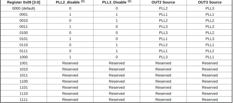
Register 0x09 [3:0] PLL2_disable PLL3_Disable OUT2 Source OUT3 Source 0000 (default) 0 0 PLL2 PLL3 0001 1 1 PLL1 PLL1 0010 0 1 PLL2 PLL2 0011 1 0 PLL3 PLL3 0100 0 0 PLL3 PLL2 0101 1 0 PLL1 PLL3 0110 0 1 PLL2 PLL1 0111 0 1 PLL1 PLL2 1000 1 0 PLL3 PLL1
1001 Reserved Reserved Reserved Reserved 1010 Reserved Reserved Reserved Reserved 1011 Reserved Reserved Reserved Reserved 1100 Reserved Reserved Reserved Reserved 1101 Reserved Reserved Reserved Reserved 1110 Reserved Reserved Reserved Reserved 1111 Reserved Reserved Reserved Reserved
(1)PLL2_DisableとPLL3_Disableは、クロスポイント・モード・ビットのステータスにかかわらず、 PLLx_DISABLEレジスタへの書き込みにより強制できます。
表 3. クロスポイント出力選択表
Vsync Code(1) Frame Rate
Number (binary) Hz 0 (0000) 23.98 Hz 1 (0001) 24 Hz 2 (0010) 25 Hz 3 (0011) 29.97 Hz 4 (0100) 30 Hz 5 (0101) 50 Hz 6 (0110) 59.94 Hz 7 (0111) 60 Hz
表 4. Vsyncコード
(1)Vsyncコードは、レジスタ0x21(Output Frame Lookup ‒ Input Vsync Code)、 0x22(Output Frame Lookup ‒ PLL2 Vsync Code)、
アプリケーション情報
機能の概要
LMH1983はフェーズ・ロック・ループ(PLL)クロック・ジェ
ネレータで、Hsync/Vsync入力リファレンス・タイミングに同
期、あるいは「Genlock」した多種多様なビデオ/オーディオ・レー
トクロックを複数同時に出力できます。4つのチャネルそれぞ
れにTop of Frame(TOF)パルス・ジェネレータを備えており、
各々のタイミングはプログラム可能でリファレンス・フレーム
に同期します。このクロック・ジェネレータは、2ステージPLL
アーキテクチャを採用しています。第1ステージはVCXOベー
スのPLL(PLL1)で、外付けの27MHz VCXOとループ・フィル
タを必要とします。Genlockモードでは、PLL1はVCXOクロッ
クを入力リファレンスに対して位相ロックさせます。入力タイ
ミング・ジッタを減衰させジッタ伝達を最小限に抑えるため、
LMH1983を狭いループ帯域幅にする必要がありますが、その
場合でも、VCXOを用いることで低位相ノイズのクロックが得
られます。外付けVCXO、外付けループ・フィルタ、プログラ
ム可能なPLLパラメータの組み合わせにより、システム設計者
はループ帯域幅とループ応答をアプリケーションに応じ柔軟に
最適化できます。
第2ステージは、モードによりますが、VCOとループ・フィ
ルタを集積した3個のPLL(PLL2、PLL3、PLL4)で構成され
ます。各PLLは、デバイスのモードにかかわらずPLL1からの
リファレンスVCXOクロック位相に常に追従します。PLL2と
PLL3は、あらかじめ設定された分周比に基づいて、VCXOク
ロック周波数の逓部と変換を行い、2つの一般的なHDクロッ
ク・レート
(148.5MHzと148.35MHz)を生成します。PLL4は、
デフォルトでは24.576MHzのオーディオ・クロックを生成する
よう設定されていますが、さまざまなアプリケーションに合わ
せて設定を変更できるよう、いくつかのレジスタがあります。
VCO内蔵PLLはPLLの安定性を確保するため広いループ
帯域幅を有しているので、適切なジッタ性能を保証するには
VCXOは安定した低ジッタのクロック・リファレンスを供給す
る必要があります。未使用のクロックやTOF出力はHi-Zモー
ドに移行させることが可能であり、これは消費電力の削減と、
動作しているクロック出力のジッタや位相ノイズを低減させま
す。TOFパルスは、フレームの開始(トップ)を示し、フォー
マットのクロスロック
(入出力のフレームレートが異なる状況)
にも対応します。出力タイミング(出力クロックおよびTOFパ
ルス)、リファレンスに対する出力タイミング・オフセット、リ
ファレンス・フレームに対する出力の初期化(アラインメント)
を出力フォーマット・レジスタで指定する必要があります。使用
しない場合は、TOF出力をHi-Zモードにすることもできます。
Genlock中にリファレンスの喪失が生じた際は、デフォルト
でPLL1をフリーランまたはホールドオーバーのいずれかで動
作させることができます。フリーランを選んだ場合、フリー
ラン制御用D/Aコンバータの出力電圧により出力周波数の精
度が決まります。ホールドオーバーを選んだ場合、ホールド・
オーバー用D/Aコンバータの出力電圧によりGenlock時の出力
位相精度を維持します。これらのオプションとPLL1の適切な
ループ応答設計を組み合わせれば、リファレンスの喪失時や
再アクイジション時の出力クロック動作を柔軟に制御できま
す。リファレンス・ステータスやPLLロック・ステータスのフラ
グは、そのステータスをリアルタイムにアプリケーション・シ
ステムに通知します。リファレンスやロック喪失を検出するス
レッショルドも設定できます。
I
2Cインターフェイス・プロトコル
I
2Cインターフェイスのプロトコルは、スタート・パルスで
始まり、7ビットのスレーブ・デバイス・アドレスとLSBに位
置する読み出し/書き込みビットからなる1バイトが続きます。
LMH1983のデフォルト・アドレスは、書き込みシーケンス用ア
ドレスが0xCC(11001100)で、読み出しシーケンス用アドレス
が0xCD(11001101)です。ベース・アドレスはADDRピンで変
更できます。ADDRを開放状態にすると0x66(シフト状態では
0xCC)、ADDRをGNDに接続すると0x65、ADDRをV
DDに接続
すると0x67になります。
書き込みシーケンス
書き込みシーケンスは、スタート状態で始まります。まず、
SCLをHighにしたままマスタがSDAをLowにし、次にスレー
ブ・アドレスが送信されます。このアドレスは7ビットのアドレ
スと、それに続く読み出し/書き込みビット
(書き込みは0)で構
成されます。デフォルト・ベース・アドレスの0x66(1100110)の
場合は、末尾に0が追加されて、最終的なアドレスは0xCCにな
ります。アドレスの後に送信される各バイトには、ACKビッ
トが続きます。SCKがHighになると、マスタがSDAラインを
解放し、スレーブがSDAをLowにして確認応答をします。デバ
イス・アドレスの次に送信されるバイトはレジスタ・アドレスで
あり、このレジスタ・アドレスとACKに続いてデータ・バイトが
送信されます。複数のデータ・バイトを送信する場合は、アド
レスが自動的に加算され、データが次のアドレス位置に書き込
まれます。「書き込みシーケンス・タイミング図」に示すように、
各データ・バイトの後にはACKビットが続きます。
読み出しシーケンス
読み出しシーケンスは、2つのI
2C転送で構成されます。最初
はアドレス・アクセス転送で、アクセス先のアドレスのみを転
送する書き込みシーケンスです。2番目はデータ読み出し転送
で、最初の転送で指示されたアドレスから読み出しが始まりま
す。その後は次のアドレスへと進み、ストップ状態になるまで
読み出し続けます。以下のタイミング図に示すアドレス・アク
セス転送は、スタート・パルス、読み出し/書き込みビット
(この
場合は書き込みを示す0)を含むスレーブ・デバイス・アドレス、
ACKビットで構成されています。その次のバイトは読み出し
対象のアドレスで、これにACKビットと、アドレス・アクセス
転送の終わりを示すストップ・ビットが続きます。続くデータ
読み出し転送は、スタート・パルス、読み出し/書き込みビット
(この場合は読み出しを示す1)を含むスレーブ・デバイス・アド
レス、ACKビットで構成されています。その次のバイトは、最
初のアクセス・アドレスから読み出されたデータです。データ・
バイトが読み出されるごとに、アドレスが加算されるので、デ
バイスからの読み出しを続けると、後続アドレスのデータも取
得できます。各バイトと先行バイトの間はACKビットで区切ら
れ、読み出しシーケンスの終わりはストップ・ビットで示され
ます。
初期化
状況によっては、LMH1983が電源立上がり時に予期せぬ状
態に陥り、PLL3の出力が大きなサイクル間ジッタを発生する
ことがあります。電源投入後に簡単なレジスタ書き込みを行う
ことで、デバイスがこのような状態に留まることを防げます。
レジスタ0x09に0x02を書き込んでから、レジスタ0x09に0x00
を書き込むことで、CLKout3が劣化したデューティ・サイクル
を示すことがなくなります。
図 1. 書き込みシーケンス・タイミング図
SCL SDA A7 A6 A5 A4 A3 A2 A1 A0 D7 D6 D5 D4 D3 D2 D1 D0 0 0 0 1 1 0 0 1 1 0 0 I2C Slave Address $CDAddress AC Data Byte n
K A C K A C K S t a r t S t o p R e a d D7 D6 D5 D4 D3 D2 D1 D0 0 Data Byte 1 AC K