Information Leakage Threats for Cryptographic Devices Using IEMI and EM Emission
10
0
0
全文
(2) Information Leakage Threats for Cryptographic Devices Using IEMI and EM Emission Ko Nakamura, Yu-ichi Hayashi, Member, IEEE, Takaaki Mizuki, Member, IEEE, and Hideaki Sone Member, IEEE Abstract—In this paper, we present a new information leakage threat combining intentional electromagnetic interference (IEMI) and observations of EM leakage. In previous studies, the analysis of secret key information in cryptographic modules using fault injection has led to methods whereby faults can be injected via low-voltage IEMI. However, the timing of fault injections cannot be controlled with this approach, and it is difficult to obtain faulty ciphertexts for use in secret key analysis by differential fault analysis (DFA). To overcome this problem, we propose a method for estimating the fault injection timing by detecting characteristic fluctuations in the EM leakage from the device. As a result, it may be possible to implement a realistic secret information analysis method applicable to a wide range of devices. First, to show the feasibility of the proposed method, we describe an experiment using an on-chip fault injection circuit that can control the injection timing. Furthermore, we apply a fault analysis method that combines the injection timing estimation method and fault injection by IEMI in a practical experimental environment. We select useful faulty ciphertexts using the proposed method, and then perform secret key analysis by DFA. Experimental results demonstrate that the secret key can be successfully analyzed. Keywords—fault analysis; EM information leakage; intentional electromagnetic interference; fault injection timing. F. I. INTRODUCTION. ault injection attacks obtain secret information by inserting faults into a target cryptographic device. The attack model of fault injection was first proposed by Boneh et al. in 1997 as an attack method against public-key cryptosystems [1]. Following this pioneering work, Biham and Shamir proposed differential fault analysis (DFA) [2] against symmetric-key cryptosystems such as the Data Encryption Standard (DES). In recent years, many DFA methods have been proposed, including those against the Advanced Encryption Standard (AES) [3-5]. With the development of fault-based attacks, various fault injection techniques have also been proposed and investigated [6-8]. Such techniques include optical fault injection using flash or laser [6]; under-powering to cause setup time violations [7]; and electromagnetic (EM) pulse injection over cryptographic integrated circuits (ICs) [8]. These fault injection techniques either require physical access to the target device or assume that the device is under the attacker’s control. Therefore, it is difficult to perform such attacks against devices with a protective mechanism such as a special chassis or a tamper detector. This work was supported by JSPS KAKENHI Grant Number 16H02831 and 17H01751. K. Nakamura and Y. Hayashi are with Nara Institute of Science and Technology, Japan (e-mail: [email protected]). T. Mizuki and H. Sone are with Tohoku University, Japan.. In recent years, a non-invasively executable fault injection method has been proposed [9]. This method injects continuous sinusoidal EM waves via cables attached to the target device, and therefore requires neither a close approach to the device nor any modification to the condition of the device. This makes fault injection easier than in previous methods, and increases the number of target devices to include those immune to conventional fault attacks. In [9], continuous sinusoidal waves of a specific frequency are injected, providing a highly efficient means of transmitting power to a device. The sinusoidal waves only cause faults in the target’s cryptographic modules, with other modules continuing to work normally. However, such continuous waves can cause faults with random timing, which makes it difficult to determine whether the observed encryption output can be used to derive secret information. In this paper, we present a method for estimating the time or processing step at which a fault occurs. In this method, the fault occurrence time or processing step is identified by observing EM leakages such as the fluctuation of EM waves emitted from cryptographic modules. Even when using a fault injection method with random timing, such as intentional electromagnetic interference (IEMI), it is possible to select some faulty ciphertext that has been output by the encryption process when a fault occurs at a specific time. Note that the conventional TEMPEST, Side-channel Attack, and Fault Injection focus on leakages or interference to degrade the security of equipment. We focus on both leakages and interference in considering the potential for security degradation. By focusing on both aspects, it is possible to analyze the secret key by DFA using the output of random-time fault injection. To evaluate the feasibility of our method, we conduct a random fault injection experiment using continuous sinusoidal EM waves via a power cable attached to a target device. In this experiment, we estimate the fault injection timing using the EM leakage observed during the cryptographic operation. In addition, we select some outputs that are injected into one or several error bytes in the intermediate result of the specific encryption step. We confirm that the secret key can be analyzed by DFA using these faulty outputs. The structure of this paper is as follows. Section II describes our fault injection time estimation method, in which fluctuations in EM leakage are observed. In addition, we present a procedure for analyzing the secret key using our estimation method. Section III describes the mechanisms of characteristic changes in the EM leakage amplitude when a fault occurs. We also report the results of an experiment to confirm the reasonability of these mechanisms. Section IV presents an experimental validation of.
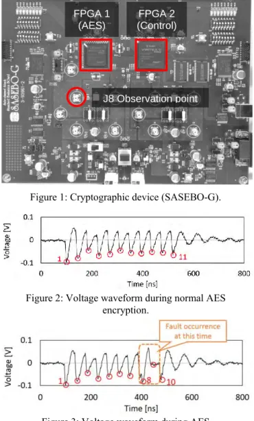
(3) FPGA 1 (AES). FPGA 2 (Control). J8 Observation point. Figure 1: Cryptographic device (SASEBO-G).. Figure 4: Fault injection attack method with proposed fault injection timing identification method. Figure 2: Voltage waveform during normal AES encryption.. Figure 3: Voltage waveform during AES encryption with fault injection. the proposed method. In the experiments, we perform IEMIbased fault injection in a practical experimental environment, and estimate the fault occurrence time using the proposed method. Finally, Section V summarizes this paper and discusses useful countermeasures against fault injection threats. II. ESTIMATION OF FAULT INJECTION TIMING USING EM LEAKAGE INFORMATION The EM leakage information used in the proposed method is obtained by measuring the electrical emanation signal responding to cryptographic module operations. This information can be observed as a voltage varying between VDD and GND in a field-programmable gate array (FPGA) or as EM leakage from a power or communication cable (the mechanisms will be discussed in Section III). In Figure 2, the waveform shows the voltage varying between VDD and GND in an FPGA mounted on a side-channel attack standard evaluation board (SASEBO)-G (Fig. 1) during the AES encryption operation. The waveform shows the voltage varying over 11 cycles,. corresponding to 10 rounds of AES encryption and one additional cycle for data I/O. When a transient fault is caused by fault injection, the leaked waveform differs from the original waveform; an example is presented in Figure 3, which shows voltage varying between VDD and GND in an FPGA on the SASEBO-G when a fault occurs in the eighth round of the AES. The amplitude of the eighth cycle is higher than in the previous waveform and the number of cycles has decreased by one. An increase in waveform amplitude is assumed to indicate the occurrence of a fault in the processing step corresponding to the peak cycle in the waveform. A. Secret Key Estimation using the Fault Injection Timing Method In terms of computational effort, secret key analysis by DFA becomes more efficient when the proposed estimation method for the fault occurrence time is used. Here, we describe the procedure for secret key analysis by IEMI-based fault injection and fault time estimation. This method is performed in two phases: the “fault injection and observation phase” and the “analysis phase.” Figure 4 gives an overview of the analysis steps. In the fault injection and observation phase, IEMI-based faults are injected into a cryptographic device through a power cable. A specific frequency of continuous sinusoidal waves is chosen and faults are injected only into the cryptographic module while all other modules in the device continue to operate without disruption. To cause such faults at specific modules, the injection frequency and excitation level are selected according to the transfer function from an injection point to the cryptographic module and the other modules. During the.
(4) Figure 5: Disturbed waveform of clock signal during IEMIbased fault injection.. A. Mechanism of Waveform Amplitude Increase and Fault Occurrence Transient faults, as shown in Figure 3, are caused by overclocking. When continuous sine waves are used for fault injection into an electric device, the waves transmitted through the attachment cable are superimposed onto the clock signal. The waveform of the clock signal on which the sine wave is superimposed is shown in Figure 5. The distorted clock signal shown in Figure 5 may exceed the threshold value at some points other than the rising edge and falling edge of the normal signal. The electric device misidentifies the overlapped waves as clock risings, which in turn causes transient overclocking. Figure 6 illustrates the correspondence between the clock signal, encryption processing time, and peak of the EM leakage waveform. The factors that result in calculation errors and an increase in waveform amplitude in the case of overclocking are as follows.. Figure 6: Amplitude increase mechanism of side-channel waveforms. injection, incorrect outputs from the fault-injected device are collected and their EM leakage is observed using a current probe with a low-pass filter attached to the power cable of the device and an oscilloscope to obtain the waveforms. Based on this, several datasets composed of three kinds of data—correct ciphertext, incorrect output, and EM leakage (as waveforms)— can be obtained. In the analysis phase, a number of available datasets are chosen based on their EM leakage. This phase employs the estimation method for the fault injection timing described above, although the conditions which incorrect output must satisfy to be suitable for fault analysis differ for each analysis method. For example, using Piret’s DFA, the AES encryption output from the seventh or eighth round, during which the fault occurs, is selected. From this faulty output, analysis methods such as DFA can analyze the secret key value. III. VALIDATION OF FAULT TIMING ESTIMATION METHOD To demonstrate the feasibility of the fault timing estimation method described in Section II, we perform an experiment to inject faults into a cryptographic device under a timingcontrollable environment. In this experiment, faults are injected at the intended timing, and the increase in waveform amplitude corresponding to the fault injection timing is observed. First, we explain the mechanism of the fault occurrences to be reproduced in the experiment and the mechanism of the waveform amplitude increase corresponding to the fault occurrence.. Mechanism of calculation error occurrence. In the normal clock cycle, such as the ith round in Figure 6, the interval tclock of the rising edges is sufficiently longer than the time tround required to execute one round of the process (tclock > tround); thus, the process is executed normally. However, when a clock glitch occurs, as in the (i + 2)th round, the shortened clock cycle t’clock is less than the execution time tround of the round process (t’clock < tround). In this case, the (i + 3)th round starts before the (i + 2)th round has been completed, and a calculation error occurs because the (i + 3)th round uses an incorrect input value. Mechanism of amplitude increase. The peaks found in EM leakage waveforms are related to IC operations. The transient current generated during the switching of the transistors constituting the IC causes a “ground bounce.” This ground bounce results in fluctuations of the power supply voltage in the IC, leakage of the common-mode current through the connection line to the outside of the device, and EM radiation, and is observed as the peak of the EM leakage waveform. Normally, in clock cycles such as the ith round in Figure 6, the round processing circuit operates only once, resulting in a transient current and EM radiation for one round of processing. However, when transient overclocking occurs, as in the clock cycles of the (i + 2)th and (i + 3)th rounds, the round processing circuit operates twice during one normal clock cycle, resulting in as much EM leakage as in two rounds. At this time, as the circuit operates twice at almost the same time, the transient current and EM radiation are higher than under normal operation. As a result, when a fault occurs, the peak amplitude of the EM leakage waveform becomes higher than under normal operation. B. Verification and Discussion of the Mechanism We inject faults into the cryptographic device using a timingcontrollable method and confirm that waveform amplitude increases corresponding to fault injection timing. In this experiment, to observe setup time violations caused by temporary overclocking in a reproducible experimental environment, a pseudo-disturbance wave is generated using a clock glitcher [10]. The clock glitcher is an on-chip fault injection circuit that can supply a glitch-inserted clock signal to the FPGA. The glitch-insertion timing can be controlled with an average resolution of 0.026 ns..
(5) Table 1: Parameters for glitch insertion experiment. Figure 7: Experimental setup for glitch insertion.. AES circuit. AES Comp. (Composite field S-Box). Clock frequency. 24 MHz. Secret key value. 0x2b7e151628aed2a6abf7158809cf4f3c. Plain text value. 0x3243f6a8885a308d313198a2e0370734. Glitch inj. target. 8th round. PERIOD value. 11.4 ns. implement an AES-128 encryption circuit in FPGA1 of the SASEBO-G and the glitcher in FPGA2. FPGA1 operates in synchronization with the clock signal (shown in Fig. 8) generated by the glitcher. The glitch-insertion timing can be set arbitrarily. Experimental parameters such as the glitch-insertion timing, secret key used for encryption, and plaintext value are presented in Table 1. The PERIOD value in Table 1 is the interval between the normal clock rising and the irregular one: the inserted clock glitch in the insertion target round (see Figure 8).. Figure 8: The glitch-inserted clock signal.. Figure 9: Waveform without glitch insertion.. Using the experimental setup in Figure 7, we inserted a clock glitch in the eighth round of the AES encryption process. The fluctuation in voltage between VDD and GND of FPGA1 during the encryption process was observed from the J8 observation point on SASEBO-G. As mentioned earlier in this section, the EM leakage waveforms related to the processing executed in the IC can also be observed as EM radiation from the IC, the leakage of common-mode current through the connection line, and so on [11]. To verify the validity of the proposed method, we measured fluctuations in the power supply voltage of the IC, which is a relatively low-noise and reproducible source of a leakage signal. The observation results are shown in Figures 9 and 10. Figure 9 is the waveform produced when encryption processing is executed normally without inserting a glitch. Figure 10 shows a waveform in the case when a clock glitch is inserted and an eighth round 1-byte error occurs. This figure confirms that there was an increase in peak amplitude in the eighth round, which was the glitch insertion target. From the above results, it is considered that the increase in the peak amplitude of the waveform and the calculation error in the ICs are caused by overclocking. It was confirmed that the peak position where the glitch insertion occurred corresponds with the amplitude increase. Therefore, by detecting the increase in the peak amplitude, the fault occurrence timing can be specified.. Figure 10: Waveform with glitch insertion. The block diagram of the experimental system is shown in Figure 7. The experimental device is a SASEBO-G. We. In this verification, the amplitude increase of the EM leakage waveform caused by the occurrence of the fault was observed as the fluctuation of the power supply line voltage in the IC. Moreover, even when fluctuations of electromagnetic wave amplitudes are observed outside the device, it is considered that a peak amplitude increase at the time of the fault occurrence can be detected. From past research [12], it is known that timing information related to processing executed in ICs leaks out of.
(6) estimate the fault injection timing in realistic attack scenarios, in this experiment, it was executed to confirm the validity of the estimation result by the proposed method. The waveforms were analyzed using the method described in Section II in order to estimate the fault injection timing. We compared the estimation results provided by these methods to determine the correspondence between them. A. Injection Timing Estimation to Analyze Experimental Results This section describes the methods used to analyze the experimentally obtained incorrect outputs and waveforms.. Figure 11: Fault-injected round estimation by backcalculation and comparison of intermediate value. the device by EM waves. In [12], it was shown that EM radiation from a power line or a communication line connected to a device can be observed with an antenna or a magnetic field probe and used for Differential Power Analysis. Experiments reported in the literature have observed fluctuations in the intensity of electromagnetic waves depending on the information processed in the device. The fluctuations are small compared with the increase in power consumption, which is noted in this paper, observed at the fault occurrence. Thus, it is possible to observe EM leakage waveforms that can be used to estimate the fault occurrence timing as fluctuations in the EM leakage amplitude. IV. CASE STUDY USING GENERIC DEVICE We performed the fault injection experiment under timinguncontrollable environments, and attempted to estimate the fault injection timing using the proposed method. In this experiment, as a case study, fault injection was performed by IEMI on a generic device (SASEBO-G) that executes AES encryption. During the fault injection, we observed the EM leakage in order to obtain waveforms for fault injection timing estimation. After the experiment, the fault injection timings were estimated and their validity confirmed. Furthermore, we analyzed the secret key by DFA using selected faulty ciphertexts based on the estimation results. Through this case study, we show that the secret key can be easily extracted without controlling the fault injection timing. An AES-128 circuit was implemented in FPGA1 and a control and communication circuit was implemented in FPGA2. An injection probe was attached to the power cable of FPGA1 and continuous sinusoidal waves were injected into the SASEBO-G through the probe and power cable. We then collected the outputs of the cryptographic module and the waveforms of varying voltage between VDD and GND of FPGA1 from observation point J8 on the SASEBO-G. Incorrect outputs were back-calculated in accordance with a decryption procedure based on the fact that we know the secret key value, and from this, we estimated the fault-injected round. Although the ciphertext back-calculation method is not available to. We first describe the method for analyzing incorrect outputs, which assumes that the secret key value for AES encryption is known by the estimator. Figure 11 illustrates the concept of fault injection timing estimation using an incorrect output and a correct ciphertext. In this method, an incorrect output and correct ciphertext are back-calculated in accordance with the decryption procedure, and intermediate values representing the input of each round of AES encryption are collected. Each intermediate value is composed of 16 bytes of data, from which the number of error bytes can be calculated through an exclusive OR operation applied to correct and incorrect intermediate values at each input round. Error bytes injected into an intermediate value of the AES are usually expanded by applying the MixColumns operation and then increasing the intermediate value. If the intermediate value from the fault-injected point is decrypted, the error bytes are expanded in the same manner as in encryption. Therefore, the smallest number of faulty bytes corresponds to the round in which the fault occurred. Note that this method cannot estimate the exact fault injection timing when multi-round faults occur. Furthermore, as the MixColumns operation is skipped in the tenth round of AES128 encryption and the error bytes are not expanded from the ninth to the tenth rounds, it is not possible to separate faults in these rounds using this estimation method. Finally, the faultinjected round cannot be estimated when a 16-byte fault occurs in one round. Despite these limitations, it is possible to use the proposed method to correctly estimate cases in which faults occur on at least a few bytes. As most fault analysis methods require several faults, the proposed method is sufficient for analyzing the results of our experiment. Next, we describe the method for analyzing the EM leakage waveforms. As described in Section II, the fault injection timing is estimated by detecting an increase in the amplitude of a cyclical waveform. Although this can also be done through visual inspection of the waveform, the large number of datasets used in our assessment made it more practical for us to write an original analysis program. In this program, 10,000 waveforms from normal encryption processes are observed and input under the no-fault scenario. The program acquires the maximum and minimum values of fluctuation at each sample point. Based on this information, the range of normal fluctuations is determined. Subsequently, to check whether any sample points exceed this range, the waveforms observed during fault occurrence are input to the program. If some sample points exceed the value of normal fluctuations, the time at which the fluctuation occurs is specified as the fault injection time. That is, this process specifies in which round the failure has occurred..
(7) Figure 13 shows the distributions of fault-injected rounds as estimated by the respective methods. In the back-calculation results in Figure 13, the ninth and tenth round faults cannot be separated; therefore, these cases are indicated as tenth round faults. Further, because 16-byte faults cannot be used to estimate the fault-injected round by back-calculation, these cases are indicated as unidentified faults (shown as “unknown”). Such 16byte faults were particularly likely to occur.. Figure 12: Experimental setup. B. Experimental Setup Figure 12 shows a block diagram of our experimental setup. As described above, a SASEBO-G was used as the test device, with an AES-128 circuit implemented in FPGA1. The SASEBO-G is controlled by a PC. The value of the encryption key is 0x2b7e151628aed2a6abf7158809cf4f3c and the plaintext is randomly generated. The clock frequency and supply voltage on the SASEBO-G are 24 MHz and 3.3 V, respectively. An injection probe (FCC F-140, 10 kHz–1.3 GHz) is attached to the power cable of the SASEBO-G. Sinusoidal waves (with frequency ~170 MHz) are generated by a signal generator (Anritsu MG3641A), amplified by an amplifier (Mini-Circuits ZHL-2-12, 10–1200 MHz), and the resulting sinusoidal waves (with voltage ~4 Vpp) are introduced into the SASEBO-G via the injection probe and power cable. An oscilloscope (Agilent DSO6104A) is used to observe and obtain the voltage waveforms between VDD and GND of FPGA1 from observation point J8. In addition, a DC-Block (Mini-Circuits BLK-89-S+) is attached between J8 and the oscilloscope, and the bandwidth limit function of the oscilloscope is used to filter out signals above 25 MHz. In this experiment, the failure timing was estimated by observing fluctuations in the power supply voltage around the IC, which is the source of the leakage signal in the experiments in Section III. Using the above setup, AES encryption was executed 150,000 times with fault injection, and encryption results and waveforms were obtained. We applied the method described in Section IV-A to these waveforms and estimated the rounds in which failures occurred. C. Experimental Results and Discussion In this experiment, we obtained 9,716 incorrect outputs originating from transient fault occurrences among 150,043 AES encryptions. We also obtained 94 incorrect outputs resulting from permanent failure occurrences. We used two methods—back-calculation of incorrect outputs and waveform analysis—to analyze all transient fault outputs in order to estimate the fault injection timing.. Figure 14 shows the distribution of the number of incorrect ciphertexts classified by the number of error bytes at each fault occurrence round. The number of error bytes was estimated using the ciphertext back-calculation method described in Section IV-A. In Figure 14, the white bars denote cases where the estimation result of the fault occurrence round by waveform analysis corresponds to the estimation result given by ciphertext back-calculation. The black bars denote cases where the estimation results did not correspond. Figure 15 presents the data in Figure 14 as percentages. In the case of errors of 13 bytes or less, the estimation results correspond in at least 90% of cases. This shows that, when a fault with relatively few error bytes occurs, it is possible to estimate the fault occurrence round using waveform analysis. However, when the errors have 14 bytes or more, the estimation results often do not correspond. This is because it is difficult to accurately estimate the fault occurrence round using ciphertext back-calculation when there are a relatively large number of error bytes. For this reason, we cannot discuss the validity of the estimation results in cases with a large number of error bytes. However, as faults in which most of the intermediate value bytes are changed produce output that is unavailable to DFA, we consider such cases to be unimportant. The results of our experiment confirm that it is possible to estimate the fault occurrence round by waveform analysis, especially when the number of error bytes is small (less than 14 bytes). D. Secret Key Analysis by DFA with Fault Injection Timing Estimation Using faulty ciphertexts obtained in our experiment, we attempted to analyze the secret key by DFA. For the analysis, we first selected ciphertexts that are available for DFA from all of the faulty ciphertexts obtained by the fault injection time estimation method. DFA was then executed using the selected faulty ciphertexts. We employed the faulty ciphertexts injected as seventh round 1-byte errors during AES encryption processing. In some cases, it is possible to specify the secret key values by DFA if at least two faulty ciphertexts satisfying this condition have been obtained. As the number of error bytes cannot be determined by the proposed estimation method, all ciphertexts judged as seventh round faults by the estimation method were analyzed by DFA. Therefore, the faulty ciphertexts to be analyzed included some which were not 1-byte errors. However, when DFA is performed using a combination of faulty ciphertexts that do not satisfy the condition (seventh round 1-byte error), the analysis result will give no candidates for the secret key. Of the faulty ciphertexts obtained by the experiment, waveform analysis estimated that 2,308 included faults that occurred in the seventh round. We attempted to analyze the.
(8) Table 2: Private key candidates identified by DFA and number of identified cases Key value. Count. K1. 0x2b7e151628aed2a6abf7158809cf4f3c. 153. K2. 0xc819e9ff28c9d24fab90e98809a84f3c. 3. K3. 0x9392aac390ae6da6131b1588b1cf4f3c. 1. (and the other 10 secret key candidates) Figure 13: Distribution of estimated fault-injected round.. Figure 14: Number of corresponding/not corresponding estimation results (by error byte count at fault occurrence).. the “key value” is specified as the key value candidate by performing DFA. When the combinations of faulty ciphertexts included those estimated to be 1-byte error faults by ciphertext back-calculation, one or more secret key value candidates were calculated. Additionally, for all such combinations, the key value 0x2b7e151628aed2a6abf7158809cf4f3c (K1 in Table 2), which was used in the experiment, was calculated as a candidate for the secret key value. Depending on the combination of faulty ciphertexts, there were cases when the number of secret key candidates could not be narrowed down to one, and a plurality of secret keys remained for the candidates. In combinations including an error ciphertext which was not a 1-byte error, no secret key candidates were obtained. As a result of DFA execution, because the key value K1 is the most frequently calculated secret key candidate, it is easy to determine that it is the correct secret key value without knowing the correct secret key beforehand. In the analysis in this section, we performed DFA to analyze the secret key value using only a small number (100) of faulty ciphertexts given by our proposed method selected from the total of 9, 716. As a result, we successfully specified the secret key value. This case study shows that the proposed fault injection timing estimation method may be useful for efficient secret information analysis in some scenarios. E. Countermeasures For cryptographic devices, in particular, the experimental results confirm the risk that the computational load of fault analysis by DFA can be reduced, as discussed in Section IV-D. Here, we describe countermeasures for the above-mentioned threats.. Figure 15: Percentage of corresponding/not corresponding estimation results (by error byte count at fault occurrence). secret key using the first 100 acquired (to reduce the computational load). Of these 100, ciphertext back-calculation estimated 18 to be seventh round 1-byte errors (this number is unknown in a realistic analysis scenario). Secret key analysis by DFA was performed for all combinations (4,950 patterns) of two from 100 faulty ciphertexts. The DFA results are presented in Table 2. “Key value” denotes the specified secret key value and “Count” represents the number of cases (number of ciphertext combinations) in which. There are three major countermeasures. These are specifically targeted against (1) fault injection, (2) observation and analysis of EM leakage waveforms, and (3) secret key analysis by DFA. Regarding (1), as mentioned in [9], applying a general EMC countermeasure (suppression of noise intrusion into the device by ferrite core or filter) for the device should result in the desired effect. Regarding (2), note that the increase in the amplitude of the EM leakage waveform used to estimate the fault occurrence timing is caused by the increase in power consumption during fault occurrence. To suppress the increased transient power consumption during fault occurrence, the equalizer circuit [13] proposed in recent years may be effective..
(9) Regarding (3), the DFA countermeasure method [14-16] is considered to be effective. V. CONCLUSION In this paper, we proposed a method for estimating the fault occurrence timing in a fault injection method without timing control. This method involves observing the cryptographic operation-derived EM leakage from a power line attached to a cryptographic device and detecting abnormal increases in waveform amplitude in order to estimate fault injection timings. Using this estimation method, we can determine whether an incorrect output obtained by fault injection is available for performing DFA. In this study, to verify the effectiveness of the proposed method, we performed fault injection experiments using actual devices, and showed that the fault injection timing can indeed be estimated. Furthermore, we discriminated faulty ciphertexts injected during a specific process (seventh round of AES encryption) from other error ciphertexts, and used them to successfully extract the secret key. The fault injection timing estimation method proposed in this paper utilizes the property that fault occurrence timing information inside the IC can be determined from EM leakage. In this paper, we focused on a cryptographic device as the target, but it can be inferred that fault occurrence timing information inside ICs can also be acquired by observing EM radiation and the like in general information equipment. REFERENCES [1]. D. Boneh, R. Demillo, and R. Lipton, “On the Importance of Checking Cryptographic Protocols for Faults,” Advances in Cryptology (Eurocrypt ’97), LNCS 1233, pp. 37-51, May 1997. [2] E. Biham and A. Shamir, “Differential Fault Analysis of Secret Key Cryptosystems,” Advances in Cryptology (Crypto ’97), LNCS 1294, pp. 513-525, Aug. 1997. [3] J. Blomer and J.-P. Seifert, “Fault Based Cryptanalysis of the Advanced Encryption Standard (AES),” Financial Cryptography: 7th International Conf., (FC 2003), LNCS 2742, pp. 162-181, Jan. 2003. [4] G. Piret and J.-J. Quisquater, “A Differential Fault Attack Technique against SPN Structures, with Application to the AES and Khazad,” Workshop on Cryptographic Hardware and Embedded Systems (CHES 2003), LNCS 2779, pp. 77-88, Sep. 2003. [5] C.-N. Chen and S.-M. Yen, “Differential Fault Analysis on AES Key Schedule and Some Countermeasures,” Australasian Conf. on Information Security and Privacy (ACISP 2003), LNCS 2727, pp. 118129, Jul. 2003. [6] S. P. Skorobogatov and R. J. Anderson, “Optical fault induction attacks,” Workshop on Cryptographic Hardware and Embedded Systems (CHES 2002), Springer Berlin Heidelberg, pp. 2-12, 2003. [7] N. Selmane, S. Guilley, and J-L. Danger, “Practical setup time violation attacks on AES,” Dependable Computing Conference (EDCC 2008), Seventh European, IEEE, pp. 91-96 2008. [8] P. Maurine, “Techniques for EM fault Injection: Equipment and Experimental Results,” Fault Diagnosis and Tolerance on Cryptography (FDTC), 2012 Workshop on, IEEE, pp. 3-4, 2012. [9] Y. Hayashi, N. Homma, T. Sugawara, T. Mizuki, T. Aoki, and H. Sone, “Non-Invasive EMI-Based Fault Injection Attack against Cryptographic Modules,” IEEE International Symposium on Electromagnetic Compatibility, pp. 763-767, Aug. 2011. [10] S. Endo, T. Sugawara, N. Homma, T. Aoki, and A. Satoh, “An on-chip glitchy-clock generator and its application to safe-error attack,” 2nd International Workshop on Constructive Side-channel Analysis and Secure Design - COSADE, pp. 175-182, 2011. [11] Y. Hayashi, T. Sugawara, Y. Kayano, N. Homma, T. Mizuki, A. Satoh, T. Aoki, S. Minegishi, H. Sone, and H. Inoue, "Information Leakage from. [12]. [13]. [14]. [15] [16]. Cryptographic Hardware via Common-Mode Current," IEEE International Symposium on Electromagnetic Compatibility, pp. 109-114, 2010. T. Sugawara, Y. Hayashi, N. Homma, T. Mizuki, T. Aoki, H. Sone, and A. Satoh, “Mechanism behind information leakage in electromagnetic analysis of cryptographic modules,” Information Security Applications, pp. 66-78, 2009. N. Miura, D. Fujimoto and M. Nagata, “Proactive and Reactive Protection Circuit Techniques Against EM Leakage and Injection,” IEEE International Symposium on Electromagnetic Compatibility (EMC), pp. 252-257, 2015. G. Bertoni, L. Breveglieri, I. Koren, P. Maistri and V. Piuri, “Error analysis and detection procedures for a hardware implementation of the advanced encryption standard,” IEEE Transactions on Computers, vol.52, no.4, pp. 492-505, 2003. K. Tiri and I. Verbauwhede, “A Logic Level Design Methodology for a Secure DPA Resistant ASIC or FPGA Implementation,” in DATE’04, IEEE Computer Society, pp. 246-251, 2004. N. Selmante, S. Bhasin, S. Guilley, T. Graba, and J-L. Danger, “WDDL is protected against setup time violation attacks,” Fault Diagnosis and Tolerance in Cryptography (FDTC), pp. 73-83, 2009.. Ko Nakamura received the B.E. in information engineering and M.S. degree in information sciences from Tohoku University, Sendai, Japan, in 2014 and 2016, respectively. He is currently working toward the Ph.D. degree in information sciences from Nara Institute of Science and Technology, Nara, Japan. His research interests include electromagnetic compatibility and information security. Yu-ichi Hayashi (M’12) received the M.S. and Ph.D. degrees in information sciences from Tohoku University, Sendai, Japan, in 2005 and 2009, respectively. He is currently a Professor in the Graduate School of Information Science, Nara Institute of Science and Technology. His research interests include electromagnetic compatibility and information security. Dr. Hayashi is the Chair of EM Information Leakage Subcommittee in IEEE EMC Technical Committee 5. Takaaki Mizuki Takaaki Mizuki (M’10) received the B.E. degree in information engineering and the M.S. and Ph.D. degrees in information sciences from Tohoku University, Sendai, Japan, in 1995, 1997 and 2000, respectively. He is currently an Associate Professor of the Cyberscience Center, Tohoku University. His research interests include cryptology and information security..
(10) Hideaki Sone (M’87) received the B.E. degree in electrical engineering and the M.E. and Ph.D. degrees in electrical communications from Tohoku University, Sendai, Japan. He is currently a Professor of the Cyberscience Center, Tohoku University. His main research interests include information telecommunication systems and instrumentation electronics..
(11)
図


+2

関連したドキュメント
After briefly summarizing basic notation, we present the convergence analysis of the modified Levenberg-Marquardt method in Section 2: Section 2.1 is devoted to its well-posedness
Internet Fraud by Fake Warnings 6 Business Service Outage Caused by Denial of Service Attacks Unauthorized Use of Internet Banking. Credentials 7 User Information Leakage from
• Primary Side Constant Current Control: thanks to a proprietary circuit, the controller is able to take into account the effect of the leakage inductance of the transformer and
Amount of Remuneration, etc. The Company does not pay to Directors who concurrently serve as Executive Officer the remuneration paid to Directors. Therefore, “Number of Persons”
• Primary Side Constant Current Control: thanks to a proprietary circuit, the controller is able to take into account the effect of the leakage inductance of the transformer and
• Primary Side Constant Current Control: thanks to a proprietary circuit, the controller is able to take into account the effect of the leakage inductance of the transformer and
during power up, then there are chances that the leakage inductance ringing is internally interpreted as a demagnetization signal and the SOFA will restart the switch: you enter CCM
• Primary Side Constant Current Control: thanks to a proprietary circuit, the controller is able to take into account the effect of the leakage inductance of the transformer and
