第 55 卷 第 3 期
2020
年 6 月
JOURNAL OF SOUTHWEST JIAOTONG UNIVERSITY
Vol. 55 No. 3
June 2020
ISSN: 0258-2724 DOI:10.35741/issn.0258-2724.55.3.23
Research article Engineering
O
PTIMIZATION OF
S
YMMETRICAL
A
IRFOILS OF THE
D
ARRIEUS
V
ERTICAL
A
XIS
W
IND
T
URBINE
达里厄斯垂直轴风轮机对称翼型的优化
Hadi Sutanto a, *, Chin-Tu Lu b , Hodik Chaiyadi aa Department of Mechanical Engineering, Atma Jaya Catholic University of Indonesia
Jakarta, 12930, Indonesia, [email protected]
b Department of Mechanical Engineering, Southern Taiwan University of Science and Technology
Tainan City, 71005, Taiwan
Received: April 28, 2020 ▪ Review: May 28, 2020 ▪ Accepted: June 5, 2020
This article is an open access article distributed under the terms and conditions of the Creative CommonsAttribution License (http://creativecommons.org/licenses/by/4.0)
Abstract
The vertical-axis wind turbine has an advantage over the horizontal-axis wind turbine because of its structural simplicity due to the independence of motion in wind direction. This article describes a new idea on how to develop the Darrieus vertical-axis wind turbine by modifying the angle of attack and adding airfoils on the wind turbine. The wind turbine has a symmetrical airfoil of NACA 0012 with three-double blade configurations to optimize the performance of the vertical shaft wind turbine. A computational fluid dynamics technique was used to understand the impact of variations of wind velocity on the angle of attack and additional distance of airfoil in turbulence intensity based on the contour of wind velocity passing the wind turbine. Using this method, the authors showed that the results of the study in turn with the variation of wind velocity, different angle of attack and additional distance of airfoil have an effect on the values of lift and drag coefficient. The highest value of the coefficient of lift is 4.1, followed by the coefficient of drag which is 0.79 at 0.3 m with the angle of attack at -4o, the wind velocity is 9.428 m/s and the result of the highest torque is 0.57 Nm which has a coefficient of performance of 1.3%.
Keywords: Darrieus, NACA 0012, Lift, Drag, Torque
摘要 垂直轴风力涡轮机比水平轴风力涡轮机具有优势,因为归因于风向运动的独立性,其结构简 单。本文介绍了如何通过修改迎角并在风力涡轮机上增加翼型来开发达里厄斯垂直轴风力涡轮机 的新思路。风力涡轮机的对称翼型为纳卡 0012,具有三双叶片配置,可优化垂直轴风力涡轮机的 性能。基于流过风力涡轮机的风速的轮廓,使用了一种计算流体动力学技术来了解风速变化对迎 角和翼型附加距离对湍流强度的影响。使用这种方法,作者表明,研究结果随风速的变化,不同
的迎角和翼型的附加距离依次对升力和阻力系数值产生影响。升力系数的最大值为 4.1,紧随其后 的阻力系数为 0.39 时的阻力系数为 0.79,迎角为-4o,风速为 9.428 多发性硬化症,最大扭矩的结 果为 0.57 牛顿米其性能系数为 1.3%。
关键词: 达里厄斯,纳卡 0012,举升,拖动,扭矩
I. I
NTRODUCTIONThe World Energy Outlook presented a scenario that the increase in global energy demand will be 37% in the year 2040, in concordance with the development of human civilization [1]. One of the most prominent energy sources is energy from fossil fuels which directly relates to carbon dioxide (CO2) emissions. The emissions of greenhouse gases like CO2 will ultimately increase the global mean surface temperature. The conflict between increasing energy demand and the degradation of the global environment become more serious. However, people are trying to find and use renewable and clean energy globally.
With a growing focus on renewable energy, interest in the design of wind turbines has also been expanding. This energy is clean, with zero CO2 emissions [2], and in its process to produce energy it does not pollute the environment [3]. Wind turbines are also simple for maintenance and have low operation costs [4]. Vertical-axis wind turbines (VAWTs), including the Darrieus wind turbine, have been demonstrated to be effective devices for extracting useful energy from the wind [5]. It has a rotating rotor for all wind directions. VAWTs have been used to generate mechanical and electrical energy at a range of scales, from small-scale domestic applications through to large-scale electricity production for utilities [6]. However, at low tip-speed ratios, the operation of Darrieus wind turbine is complex because of the presence of the dynamic stall conditions [7]. On the other side, the development of VAWTs are limited because of their poor starting ability. Researchers have conducted various experiments to study the impact of the performance of VAWTs related to the number of blades and torque [8], the optimized pitch angle of the blades to improve self-starting [9], the shape of high digit and low digit of the NACA 00xx airfoils on the performance of the wind turbine using numerical analysis [10], and also the different Reynolds numbers [11] or the solidity of the rotor with computational fluid dynamics (CFD) [12]. To reduce the problem of starting these wind turbines, a different structure of Darrieus wind
turbine was developed using other blades installed on one radial strut.
The purpose of the present paper was to study Darrieus-type vertical-axis wind turbines on the design of a wind-turbine rotor with two sets of NACA 0012 airfoil blades to evaluate the torque, power output related to the stall effect, tip-speed ratio, and attack angles using computational fluid dynamics (CFD) analysis.
II. T
HED
ARRIEUS-T
YPEV
ERTICAL-A
XISW
INDT
URBINEIn general, a wind turbine converts wind energy into mechanical energy to produce electricity. There are two basic types of wind turbine, horizontal-axis wind turbines (HAWTs) and vertical-axis wind turbines (VAWTs). Compared with HAWTs, VAWTs have more advantages, such as a simpler structure, easier installation, no requirement for incoming wind, suitability for small-scale energy generation, and low cost [13], [14]. VAWTs are driven by two types of wind forces: a lift force (FL) and drag force (FD). Based on their structures, the Savonius-type VAWTs are driven by an aerodynamic drag force, but the Darrieus-type VAWTs are driven by an aerodynamic lift force [15], [16].
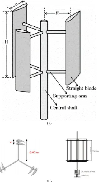
Figure 1a shows the traditional three-bladed Darrieus-type VAWT with one set of blades. The given airfoil is characterized by the height (H), rotor radius (R), number of blades (Nb = 3) and
blade chord (c). When the rotor is subject to an instantaneous incoming wind speed Wo(t), it will turn at a rotational speed ω(t). The new structure Darrieus wind turbine is shown in Figure 1b, where another blade has been added on the radial arm. This type of Darrieus wind turbine is called the Darrieus wind tubine with two sets of blades.
The lift and drag coefficients, in Houghton et al. [17], are given by the following equations:
CL = (1)
where ρ is the density of the fluid (kg/m ), v is the wind velocity (m/s), and A is the swept area of the turbine blade (m2). CL and CD are
experimentally determined using empirical data and depend on the angle of attack (α).
If the lift coefficients of a set of blades are higher than the drag coefficients, the rotor of the wind turbine will rotate, but if the lift coefficients are smaller than the drag coefficients, the turbine will not rotate. The drag coefficients inhibit the turbine to rotate. The drag coefficients are related to the stall effect. If there is a stall effect (Figure 2a), the coefficients of drag will increase. A stall effect is a phenomenon when the angle of attack is very large or the flow rate is too large, then the laminar flow of the air can become turbulent, and the air stream may separate from the back of the turbine. It will have results in the separation of the backflow of the blades. This situation significantly decrease the lift force and increase drag force or the rotation of the rotor is inhibited.
(a)
(b)
Figure 1. (a) Three-bladed Darrieus-type VAWT; (b) Three double blades of Darrieus-type VAWT
When the blades rotate the local angle of attack α varies with the relative velocity Wr. The
incoming wind speed W0 and the rotational
velocity of the blade ω govern the orientation and magnitude of Wr [18]. In turn, the forces FL and FD acting on the blade are vary. Similarly are the magnitude and orientation of the lift and drag forces as well as the resultant force. The resultant force can be decomposed into the normal force
FN and the tangential force FT (Figure 2 b). The
tangential force component then drives the rotation of the wind turbine and produces the torque necessary to generate electricity [19].
The torque of rotor is determined by
(3) where I is moment of inertia (kgm2), and α is angular acceleration (rad/s2).
(a)
(b)
Figure 2. (a) Stall effect on airfoil, (b) Velocity and force components of airfoil
Then the wind turbine power Pt is given by
equation (4) as
where τ is torque (Nm), ω is angular velocity (rad/s).
The wind energy is given by the following equation,
Pw= mv3 (5)
where Pw is wind energy (Watt), m is mass (kg), v is wind velocity (m/s). The equations of wind
energy and wind turbine power determine the coefficient of performance for the wind turbine. The coefficient of performance (Cp) is a measure
of efficiency of wind turbine because Cp is also
equal to Pr/P, where Pr = power of the rotor of wind turbine and P = total power of wind turbine. The coefficient of performance for the wind turbine is given by the following equation:
Cp = (6)
Another parameter that affects the coefficient of performance (Cp) for a wind turbine is the tip
speed ratio (TSR) as the ratio of the turbine rotation to the wind velocity. The equation of the
TSR is as follows:
TSR = β = (7)
where ω is the angular velocity (rad/s), R is the turbine radius (m), and v is the wind velocity (m/s).
III. M
ETHODOLOGY FORC
OMPUTATIONALF
LUIDD
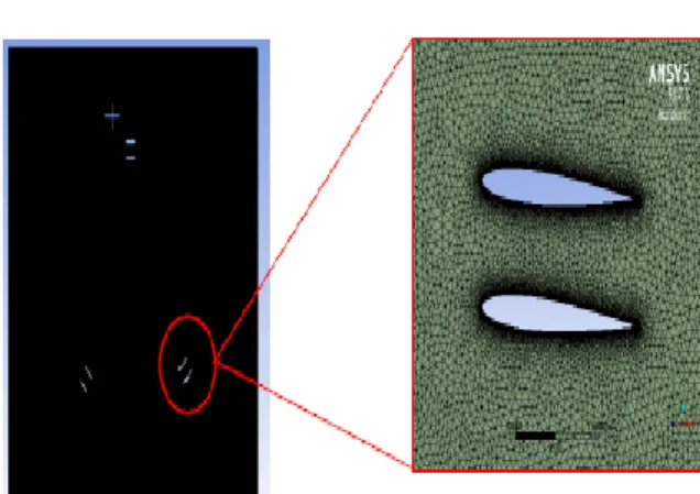
YNAMICSComputational fluid dynamics (CFD) has been a major approach for addressing fluid flow problems like analyzing the lift and drag force of wind turbines. This study used a 2D square computational domain with rectangle-type as shown in Figure 3. The direction of the arrows indicates the starting point of the computation process and inlet. While the upper and lower domain borders are symmetrical, the backside domain boundary is the outlet, and the airfoil is the wall. Figure 4 shows the shape of the mesh using the NACA 0012 airfoils. The ANSYS Fluent code usually performs the simulation of the airfoil motion.
Figure 3. Rectangle - type which has the size W = 1.5 m and
L = 1.5 m
Figure 4. The shape of domain with rectangle-type meshing using NACA 0012 airfoils
Variations of wind velocity (1.886, 2.095, 2.357, 2.694, 3.143, 3.771, 4.714, 6.287, 9.428, and 18.857 m/s) were applied in this study with angle of attack variations (−6o, −4o, −2o, 0o, 2o, 4o, and 6o) and additional airfoil distance variations (0.15, 0.2, 0.25, 0.3, 0.35, and 0.4 m). The CFD method was performed with an unstructured mesh shape and used the K-epsilon turbulence model equation.
IV. R
ESULTS ANDD
ISCUSSIONUsing the ANSYS Fluent program while varying the angle of attack, the distance between the additional airfoil, and the wind velocity, the coefficients CL and CD and torque τ could be
gained directly from the simulation. The most optimum design with the highest torque was related with an angle of attack of −40. The results showed that at a wind speed of 9.428 m/s the average variation of the angle of attack had started to rotate at an airfoil distance of 0.15 m. In addition, at an airfoil distance of 0.3 m with the angle of attack at −40, the maximum torque was generated at 0.57 Nm as seen in Figure 5. The reason is that the stall effect was smaller at an airfoil distance of 0.3 m compared to a distance of 0.15 m with a similar wind velocity. Figure 5 also shows that all of coefficients of lift
CL were higher than all of coefficients of drag CD.
It means that that the rotor of the wind turbine started to rotate when CL > CD.
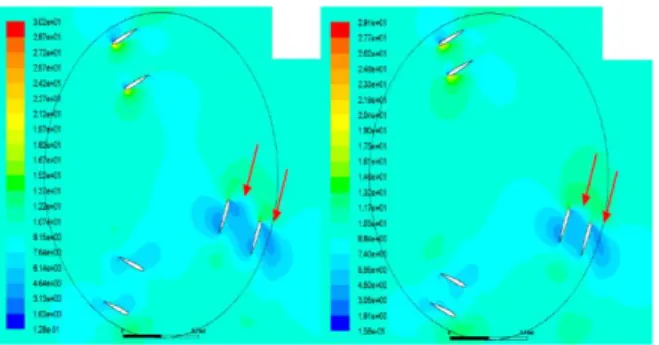
From Figure 6, it was shown that there was a stall effect on the new design of the Darrieus vertical-axis wind turbines. On the modified turbine design, the stall flow rate on the top airfoil was around 6.74 to 8.07 m/s. The higher flow rate occurred on the top of the airfoil with the stall effect reducing the lift force of the turbine. The results have shown that the drag force of the wind turbine is higher than the lift force.
Figure 5. Graph of optimum coefficients CL, CD, CP and
torque τ (Nm) vs distance between addition airfoil (m), at the angle of attack α = -40 and the wind velocity v = 9.428
m/s
Figure 6. Stall effect at the angle of attack - 40 and the wind velocity v (a) 3.13 m/s and (b) 4.05 m/s
The stall flow rate at the top airfoil, with the distance between additional airfoils being 0.3 m, is between 1.63 m/s to 3.13 m/s. The stall flow at the bottom airfoil, with the distance being 0.35 m, is 3.05 m/s to 4.5 m/s. This results in a lower torque (as seen in Figure 6). The result will be similar when the distance is 0.15 m and the stall flow rate at the top airfoil is 3.24 m/s to 4.81 m/s, when a 0.20 m distance has a stall rate at 3.23 m/s to 4.79 m/s and when a 0.25 m distance has a stall rate at 3.18 m/s to 4.71 m/s. The higher wind velocity occurs at the top of the airfoil; then the stall effect reduces the lift force of the wind turbine. If the stall effect decreases then the coefficient of lift CL increases, otherwise the drag
force will be smaller than the lift force. The distance of the added airfoil, 0.3 m, with a wind speed of 9.428 m/s and an angle of attack of 40, has the highest torque and the coefficients of lift and drag, CL and CP.
V. C
ONCLUSIONThe lift-type wind turbine with two sets of blades is investigated with reference to the effect of the distance between the two sets of blades on the coefficients of lift and drag and torque. When the torque is positive the rotor of the wind turbine starts to rotate that the symmetrical blades are better than a traditional rotor with one set of blades. To conclude this work, the following conclusions can be drawn:
a) variations in angle of attack with a set distance between the two sets of blades increases the torque of the rotor related to increasing the coefficient of lift CL;
b) when the distance of the added airfoil is 0.3 m and there is a wind speed 9.428 m/s and an angle of attack of 40, this produces the highest torque at 0.57 Nm and the coefficients of lift and drag are CL = 4.1 and CP = 0.79;
c) for the velocity contour, when the distance of added airfoils increases the stall effect decreases;
d) other parameters of the Darrieus-type wind turbine with added airfoils, such as the blade chord length, the pitch f, and the offset angle of airfoils, needs more discussion to improve the performance of wind turbine.