A method for evaluation of the effects of attachments in aligner-type orthodontic appliance:
Three-dimensional finite element analysis
Abstract
Purpose Many patients require esthetic orthodontic treatment. Aligners, such as Invisalign® (Align
Technology, Santa Clara, Calif.), have recently become widely used in such cases. However, orthodontic treatment occasionally causes unexpected tooth movement called the bowing effect. For example, when premolars are extracted during treatment, molars tend to tip toward the extracted area.
Recently, small composite attachments have been recommended with the aim to generate effective orthodontic force to prevent the bowing effect. However, the mechanism of tooth movement with attachments of aligner-type appliances is not yet clear.
Materials and Methods In this study, we evaluated the effects of attachments on aligner treatment
with finite element analyses.
Results In this study, the computational results with finite element analyses show that the shape and
position of attachments have no influence on tensile force and tipping moment. Differences in delicate positioning of attachments changed the analytical results.
Conclusions We suggest that appropriate model setting is important to evaluate the effect of attachment by finite element analyses.
Key words: orthodontics, aligner, attachment, finite element method, tooth movement
1. Introduction
Orthodontic treatment has traditionally been performed with wires and braces. Many patients require esthetic orthodontic treatment, and aligners have been used for this purpose. In recent years, aligner treatment has become popular worldwide for orthodontic therapy as an alternative to fixed labial braces [1-4]. Thermoplastic appliances, such as Invisalign®, have recently been used widely in such cases. The Invisalign® aligner was developed by Align Technology Corporation in 1999, and has been widely adopted for orthodontic therapy [1]. In this system, three-dimensional models of patients’ dentition are constructed, and the movement of each tooth to the target position is simulated using a computer. After dentists approve the simulation, serial aligner stages are produced from thermoplastic resin and multiple aligners are prepared. Tooth movement of 0.25 mm is automatically produced with each aligner. Each aligner is worn for 2 weeks during the treatment. Such treatment is more uniform than wire treatment. Invisalign has the advantages of being transparent, inconspicuous, and removable. However, in some cases, the actual tooth movement differs from that predicted by the pretreatment analysis (Clincheck®). This unexpected movement may be attributed to the fact that the mechanism of tooth movement with aligners differs markedly from that of the conventional wire method. More difficult movements, such as bodily movement for extraction space closure, were less successful [1]. In particular, in cases involving premolar extraction, adjacent teeth may incline toward the extraction space—a phenomenon called the “bowing effect”.
In orthodontic treatment with aligners, the appliance covers the entire tooth crown. Therefore, it is difficult to judge where force and moment are applied. Many mechanical analyses of wire treatment have been performed using finite element (FE) methods [5-9]. However, few studies have performed mechanical analyses of aligners. We reported the behavior of the bowing effect with computer simulation [10].
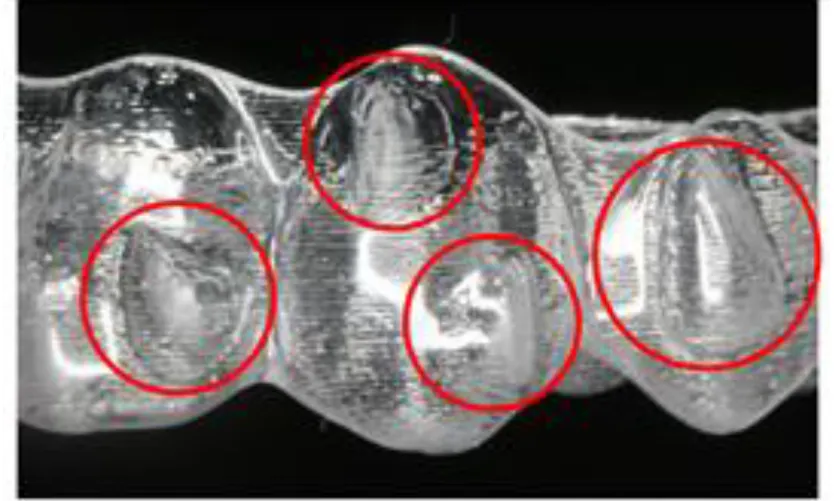
Recently, Align Technology Inc. recommended the use of resin attachments to aid rotational movement and improve the predictability of orthodontic movement (Fig.1) [11]. Attachments [12] in the form of bumps are set on the tooth surfaces in order to provide a 3-dimensional shape to the crown morphology using composite resin and to strengthen the retentive force of the aligner. The
aim is to achieve the optimal orthodontic force of the aligner.
Boyd, Vlaskalic [13] and Boyd [14] suggested the use of labial and lingual attachments to aid rotational movement with Invisalign. Using FE analysis, Gomez showed that greater bodily tooth movement is likely to occur in the presence than in the absence of attachments [15]. However, they did not analyze the contribution of differences in the shape and position of attachments to tooth movement behavior. Moreover, FE analysis was performed with only the canines. Conversely, Kravitz et al.’s investigation showed that attachments did not significantly improve the accuracy of tooth rotation [16].
Therefore, the aim of this study was to use the force theorem to analyze the force system introduced by resin attachments in aligner treatment. We report changes in tooth movement resulting from differences in configuration and position of attachment.
2. Materials and Methods
To investigate the orthodontic force induced by aligners, contact areas between the tooth crown and aligner were evaluated using FE analysis. We performed FE analysis with two tooth models: the canine and second premolar. Construction of the basic FE model was based on computed
tomography (CT) scans (80 kV, 20 μA [crown area], 90 μA [root area], 600 slices/scan, and 48-μm slices; ScanXmate-L080HT, Comscantecno Corporation, Kanagawa, Japan) of teeth models. Two artificial teeth (canine and second molar) were fixed at 2.5 times the size of actual teeth (B10-330, Nissin Dental Products, Kyoto, Japan). A FE model was subsequently created from CT DICOM data based on the artificial tooth model. Analysis was performed using mechanical analysis software (Marc V2011 [Advanced Nonlinear Simulation Solution], MSC Software Corporation, Sunnyvale, CA, USA). For numerical calculation, Marc V2011 (Advanced Nonlinear Simulation Solution) was used. For the preprocessor and postprocessor, Mentat V2011 was used. The crown heights of the tooth models are presented in Fig. 2
The periodontal ligament (PDL) was assumed to be a layer with a constant thickness of 0.2 mm—a widely adopted convention in existing literature [17-20]. Since the height of the periodontal ligament is different between the actual canines and premolars, this difference was simulated in the FE model. Although the actual morphology of the periodontal ligament is a complex curve, it was presented as a straight line in the models for convenience.
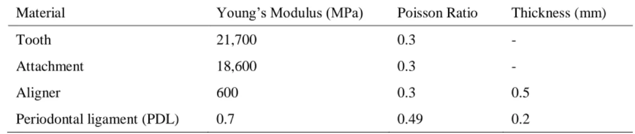
Four materials were used in this study. The material properties were determined from the values documented in the literature (Table 1) [16,21]. Then the material properties were assigned to teeth, attachments, the aligner, and PDL. The aligner was produced from shell elements that occupied the same coordinates of the tooth crown. The thickness of the aligner was set at 0.5 mm, and Coulomb’s friction coefficient of the aligner and tooth coronal surface was set at 0.5.
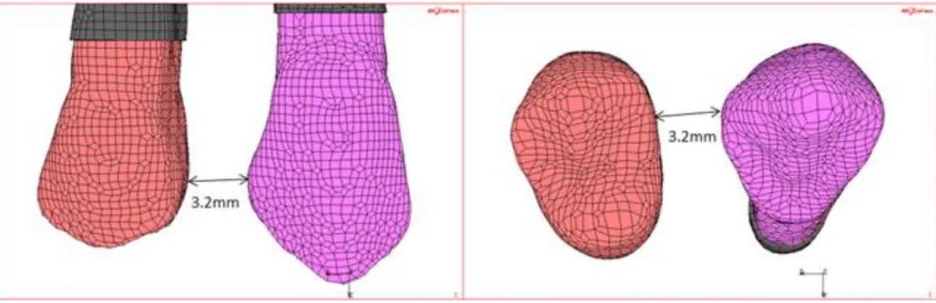
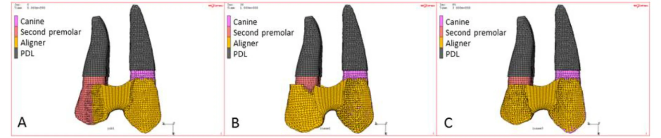
The mechanism of producing an orthodontic force by covering the teeth with an aligner was reproduced following the analytical procedure described below on the assumption of canine distal retraction. The tooth models of the canine and premolar before movement are shown in Fig. 3. In the initial setting, the canine and premolar were arranged with a 3.2-mm interval at the maximum bulged
region. The covering aligner was set so as to acquire the best fit when the interval narrowed by 0.25 mm from the initial interdental distance. When this aligner is applied, the 2 tooth models are drawn towards each other. To analytically present the behavior of covering the teeth with the aligner, the function to simulate the addition of thermal expansion to each shell element of the aligner was utilized, i.e., expansion of the aligner was simulated by changing the thermal expansion coefficient and attached. Then, the thermal expansion coefficient was returned to the original value to reduce the aligner’s size to the original size. Since the interdental distance in the covering aligner was smaller than that in the covered teeth by 0.25 mm, an orthodontic force drawing the 2 teeth closer is produced (Fig.4).
The aligner was applied to the premolar from the back due to the analytical procedure, but the tensile force and tipping moment were analyzed focusing on the canine. In contact analysis, the contact condition between the aligner and canine after this size reduction was sequentially computed, and the final contact distribution between the orthodontic force and tooth was determined.
The mechanical conditions of the FE model were set as follows: The analysis methods used were the contact and large displacement methods (for the analytical methods, contact and large
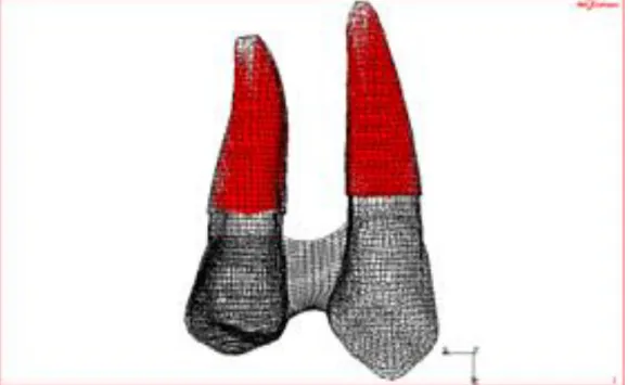
deformation theory were employed). Since the periodontal ligament was integrated with the tooth, it was excluded from the contact group. Rigid elements were set; the central point of the surface height of the tooth with the periodontal ligament buried in bone was regarded as an independent node and nodes on the outer surface of the periodontal ligament as dependent nodes. The constraint point was set in each of the canines and premolars, and the reference point for the tensile force and tipping moment was set to the center of the upper end of the constraint point (Fig. 5). The tensile force and tipping moment were calculated as follows and the evaluation point was set to the canine constraint point (Fig.6).
The tensile force represents the reaction force at the canine constraint point in the presence of coverage with the aligner, in which the interdental distance was slightly reduced due to the influence
Tensile force: The sum total of the reaction forces in the X-direction at nodes (i) on the periodontal ligament surface (boundary plane with bone)
N
Σ
Rxii=1
N: Number of surface nodes
Rxi: Reaction force in the X-direction
For the tipping moment, referring to the product of the force and distance vectors of nodes on which the force around the tooth root is loaded, the canine constraint point was regarded as the reference point for calculation of the tipping moment.
Tipping moment: The sum total of the distances from the reaction force × evaluation point in the X&Z-directions of nodes (i) on the periodontal ligament surface (boundary plane with bone)
N
Σ
Rxi*Lzi+Rzi*Lxii=1
Rx: Reaction force in the X-direction Rz: Reaction force in the Z-direction
Lx: Distance from the evaluation point in the X-direction Lz: Distance from the evaluation point in the Z-direction
Attachments were divided into 2 types and analyzed. In this study, we classified the attachment models into two types. One type was a pair of attachments recommended by Align Technology, Inc.,
Optimized root control attachments® [22]. The shape and size of this product are automatically custom-made corresponding to the movement pattern and crown morphology and the attachment is automatically set. The distance between the attachment pair was varied: the longitudinal distance was changed in Nos. 1-5, and the horizontal distance was changed in Nos. 5-7. No. 8 was prepared to investigate differences due to the size. The other type was termed vertical rectangular attachments [1] and 3 types with different sizes in the longitudinal direction were prepared and designated as Nos.
9-11. The different attachment models are shown in Table 2 and Fig. 7.
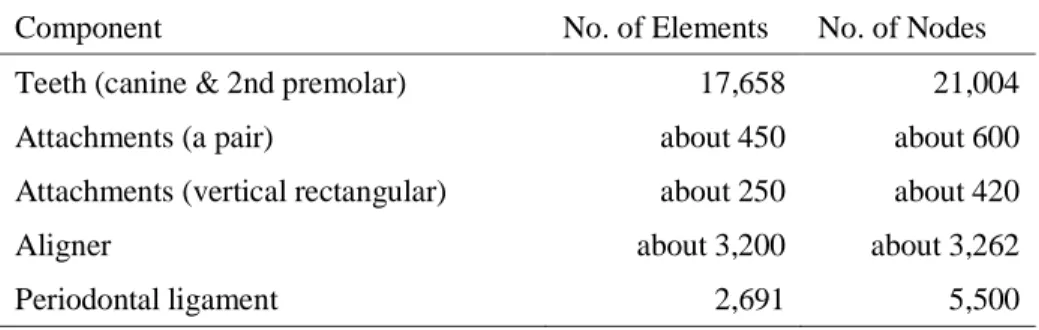
The meshing of the aligner model was constructed with shell elements, and that of the other model with hexahedral elements. The number of elements and nodes for each component of the model are shown in Table 3. Including the model with no attachment (No. 0), the contact distribution map,
‘tensile force’, and ‘tipping moment’ were calculated.
3. Results
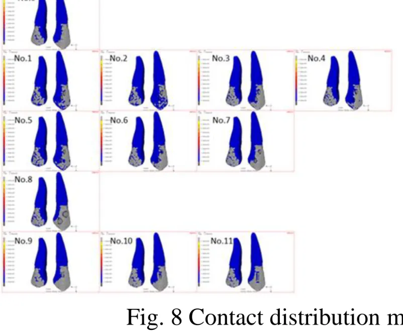
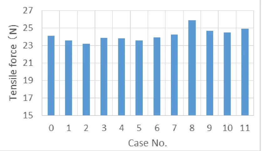
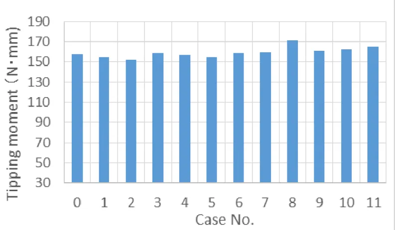
Figure 8 shows the contact distribution map for each tooth model. Gray regions indicate areas in which the force of the aligner on the crown (contact pressure) exceeded 1.0×10⁻⁸ Pa. No marked difference from that in No. 0 was noted in Nos. 1-6, but the gray area in the canine crown part was wider in Nos. 7-11 than in No. 0 with no attachment. Figures 9 and 10 show the calculated aligner tensile force and aligner tipping moment. The ‘tipping moment/tensile force ratio’ is shown in Fig.
11. The grade of falling may decrease as this value decreases. Based on the analytical findings, no marked difference was noted in either tensile force or tipping moment among attachment Nos. 1-12, excluding No.8. In No.8, both tensile force and tipping moment were greater by about 7%. In the
‘tipping moment/tensile force ratio’, no finding showed a specific tendency associated with the arrangement or size of the attachment. For example, both tensile force and tipping moment were high in No. 8, but these values were higher than the mean by 0.4%, and no preferable effect inhibiting the tipping moment was noted. In Nos. 1-7, the analytical findings varied due to small changes in the position of the attachment, but no specific relationship was noted between the interval of the attachment pair and analytical findings.
The Von Mises stress distribution of the aligner is shown in Fig. 12. The bright region represents a strong tensile stress. No marked difference was noted among the attachments.
4. Discussion
In this study, we investigated the effect of attachments of aligners using FE analysis with reference to the contact state. Many changes were made in the position and size of the attachment, and the effect of the attachment was analyzed using the FE method. The position of the attachment pair was changed and the effect was compared among distances in the horizontal and longitudinal directions, but the findings did not show a clear linear trend. The accuracy of the analysis was investigated. The numerical error of the analysis was less than 1/100,000, confirming that there was no problem with the calculation accuracy of the contact analysis. However, minute differences in the attachment position and slight changes in the crown morphology caused variations in the analytical findings. The aligner used in this study differed in shape from the actual aligner, having no segment in contact with the 2 adjacent teeth. Since the aligner covered only 2 teeth, it was not likely to float from the teeth, which may have made it difficult to observe the effect of the attachment. We are planning to prepare a model with segments in contact with the 2 adjacent teeth, and use it for the analysis regarding the shape of the dentition.
5. Conclusions
This study made it possible to visualize the tendency of tooth movement and inclination by aligner. No marked difference was noted in the effect of the attachments with change in shape and position. Probably the effect of the attachment will depend on the shape of the tooth. If the tipping moment can be predicted by simulation corresponding to the crown morphology of individual patients before treatment in clinical practice, it may be incorporated into the orthodontic appliance, which is very useful. By using these simulation models, we aim at establishing an analysis system capable of predicting the effect of orthodontic appliances based on the crown morphology in individual patients prior to treatment. The analysis models involved only 2 teeth and surrounded the crown parts in contrast to actual aligners, which cover the whole dentition. There is still scope to modify the model, such as the opening of both ends of the aligner to conform to the actual aligner shape. Since the method of analysis was confirmed to be reliable, we will continue studies using this analysis method. We will also investigate the effective attachment setting conditions as well as a method to change the initial shape of the main body of the aligner, such as a setting that inhibits disadvantageous movement by intentionally loading a moment in the opposite direction.
References
[1] Boyd RL. Esthetic orthodontic treatment using the Invisalign appliance for moderate to complex malocclusions. J Dent Educ 2008;72:948-967.
[2] Kravitz ND, Kusnoto B, BeGole E, Obrez A, Agran B. How well does Invisalign work? A prospective clinical study evaluating the efficacy of tooth movement with Invisalign. Am J Orthod Dentofacial Orthop 2009;135:27-35.
[3] Kuo E, Miller RJ. Automated custom-manufacturing technology in orthodontics. Am J Orthod Dentofacial Orthop 2003;123:578-581.
[4] Meier B, Wiemer KB, Miethke RR. Invisalign-patient profiling. Analysis of a prospective survey.
J Orofac Orthop 2003;64:352-358.
[5] Canales C, Larson M, Grauer D, Sheats R, Stevens C, Ko CC. A novel biomechanical model assessing continuous orthodontic archwire activation. Am J Orthod Dentofacial Orthop
2013;143:281-290.
[6] McGuinness BN, Wilson AN, Jones M, Middleton J, Robertson NR. Stresses induced by edgewise appliances in the periodontal ligament-a finite element study. Angle Orthod 1992;62:15-22.
[7] Cattaneo PM, Dalstra M, Melsen B. The finite element method: a tool to study orthodontic tooth movement. J Dent Res 2005;84:428-433.
[8] Geramy A. Bodily labializing lateral incisors: 3D analysis using finite element method. Acta Odontol Scand 2013;71:570-576.
[9] Kojima Y, Fukui H. Numerical simulation of canine retraction by sliding mechanics. Am J Orthod Dentofacial Orthop 2005;127:542-551.
[10] Fujita Y, Kimura H, Yanagisawa W, Inou N, Maki K. Experimental verification of finite element analysis for thermoplastic orthodontic aligner. The Showa University Journal of Medical Sciences 2014;26:139-147.
[13] Boyd RL, Vlaskalic V. Three-dimensional diagnosis and orthodontic treatment of complex malocclusion with the Invisalign appliance. Semin Orthod. 2001;7:274-293.
[14] Boyd RL. Predictability of successful orthodontic treatment using Invisalign. The Greater Philadelphia Society of Orthodontists page. Available at: http://www.gpso.org/events/ 2003 outline.pdf. Accessed September 1, 2007.
[15] Gomez JP, Peña FM, Martínez V, Giraldo DC, Cardona CI. Initial force system during bodily tooth movement with plastic aligners and composite attachments: A three-dimensional finite element analysis. Angle Orthod 2015;85:454-460.
[16] Kravitz ND, Kusnoto B, Agran B, Viana G. Influence of attachments and interproximal reduction on the accuracy of canine rotation with Invisalign: A prospective clinical study., Angle Orthod 2008;78: 682-687.
[17] Qian Y, Fan Y, Liu Z, Zhang M. Numerical simulation of tooth movement in a therapy period.
Clin Biomech 2008;23:S48-52.
[18] Coolidge ED. The thickness of the human periodontal membrane. J Am Dent Assoc Dent Cosmos 1937; 24: 1260-1270.
[19] Liang W, Rong Q, Lin J, Xu B. Torque control of the maxillary incisors in lingual and labial orthodontics: A 3-dimensional finite element analysis. Am J Orthod Dentofacial Orthop
2009;135:316-322.
[20] Kojima Y, Fukui H. Numeric simulations of en-masse space closure with sliding mechanics. Am J Orthod Dentofacial Orthop 2010;38:702.e1-6; discussion 702-4.
[21] Qian Y, Fan Y, Liu Z, Zhang M. Numerical simulation of tooth movement in a therapy period.
Clin Biomech (Bristol, Avon). 2008;23 Suppl 1:S48-52. Epub 2007 Oct 17.
[22]
http://www.aligntech.ru/documents/Invisalign%20G4_Brochure.pdf#search=‘Optimized+Attachmen ts’
.
Figure Captions
Fig. 1 Aligner with attachments denoted by circles Fig. 2 Scale of tooth models
Fig. 3 Interdental distance before movement Fig. 4 Analysis method
A. When the teeth were not covered with the aligner, the interdental distance was shorter than the initial setting by 0.25 mm. B. The aligner was expanded by changing the thermal expansion coefficient. C. When the expansion coefficient was returned to the original value, the aligner returned to the original size and covered the teeth.
Fig. 5 Rigid elements setting regarding the nodes on the outer surface of the periodontal ligament as dependent nodes
Fig. 6 Constraint points (evaluation points) in the canine and premolar Fig. 7 Attachment patterns
Fig. 8 Contact distribution map (Case No. corresponds to Table 2) Fig. 9 Aligner tensile force (Case No. corresponds to Table 2) Fig. 10 Aligner tipping moment (Case No. corresponds to Table 2)
Fig. 11 Ratio of tipping moment to tensile force (Case No. corresponds to Table 2)
Fig. 12 Von Mises stress distribution of aligner (Case No. corresponds to Table 2)
Table 1 Material properties
Material Young’s Modulus (MPa) Poisson Ratio Thickness (mm)
Tooth 21,700 0.3 -
Attachment 18,600 0.3 -
Aligner 600 0.3 0.5
Periodontal ligament (PDL) 0.7 0.49 0.2
Table 2 Attachment variation
Optimized Attachments No. Height×width
(mm)
Vertical space (mm)
Horizontal (°)
0 Not exist
1
2×1
0
0
2 0.5
3 1
4 1.5
5
6 2 10
7 20
8 3×2 0 0
Vertical rectangular attachments
No. Height×width (mm)
9 2×1
10 3×1
11 4×1
Table 3 The number of elements and nodes for each component of the model
Component No. of Elements No. of Nodes
Teeth (canine & 2nd premolar) 17,658 21,004
Attachments (a pair) about 450 about 600
Attachments (vertical rectangular) about 250 about 420
Aligner about 3,200 about 3,262
Periodontal ligament 2,691 5,500