Applicability of ionic liquid electrolytes to LaSi2/Si
composite thick-film anodes in Li-ion battery
Hiroyuki Usui, Masahiro Shimizu, and Hiroki Sakaguchi*
Department of Chemistry and Biotechnology, Graduate School of Engineering, Tottori University 4-101 Minami, Koyama-cho, Tottori 680-8552, Japan
*Corresponding author. Tel./Fax: +81-857-31-5265; e-mail: [email protected]
Keywords: Si-based anode; LaSi2/Si composite; Ionic liquid electrolyte; Thick-film electrode;
Gas-deposition method; Li-ion battery
Abstract
Anode performances of LaSi2/Si composite thick-films were investigated in ionic liquids as
Li-ion battery electrolytes containing cations of N-methyl-N-propylpiperidinium (PP13) or 1-ethyl-3-methylimidazolium and anions of bis(fluorosulfonyl)amide (FSA) or bis(trifluoromethanesulfonyl) amide. The LaSi2/Si electrode exhibited much better performance in
PP13-FSA compared with the other electrolytes including a conventional organic solvent one: the reversible capacity at the 250th cycle and its retention were 800 mA h g−1 and 80%. The excellent
performance is attributed to a higher stability of PP13 cations against a cathodic decomposition and an easier desolvation of Li ions and FSA anions at the electrode/electrolyte interface. This result offers a promising applicability of ionic liquid electrolyte to various Si-based anodes with high performances by architecture of cation and anion structures.
1. Introduction
Silicon-based materials are highly anticipated to be applied to a high-capacity anode (negative electrode) in the next-generation Li-ion battery. Silicon and lithium form several binary alloy phases, Li12Si7 (Li1.71Si), Li7Si3 (Li2.33Si), Li13Si4 (Li3.25Si), and Li22Si5 (Li4.4Si) at a high temperature of
415oC [1,2]. On the other hand, at a room temperature, silicon can electrochemically react with Li to
form a binary alloy of Li15Si4 [3-10]. As an anode of Li-ion battery, these fully-lithiated phases of
Li22Si5 and Li15Si4 provide vast theoretical capacities of 4200 and 3580 mA h g−1, respectively. The
capacities are much superior to that of graphite anode currently used in commercial Li-ion batteries. A critical hurdle, however, still remains for a practical use Si anodes in Li-ion batteries. Crucial disadvantages of Si as an anode material are its high electrical resistivity, a low diffusion coefficient of Li in Si (10–14–10–12 cm2 s–1 [11-13]), and severe changes in its specific volume during
Li-insertion/extraction. The expansion ratios of the specific volume from Si to Li22Si5 or Li15Si4
reach approximately 410% [14,15] or 380% [10]. As a result of the volume changes, stress is continuously accumulated in the active material by repeating charge–discharge cycle. This leads to cracking and pulverization of the active material, which causes that a large portion of the active material loses an electrical contact with the current collector. Si anodes, therefore, show a rapid capacity fading and a poor cycle-life performance. To overcome this problem, many attempts have been made for Si-based anodes. In these days, a large number of studies have been made on Si dispersed in various Li-active or Li-inactive matrices. Typically, carbonaceous materials, metals, alloys, and oxides have been studied as the matrices.
Applicability of electrolyte to electrode is also one of the most important factors to improve electrode performance. One of typical commercialized electrolytes is based on a mixture of organic solvents, ethylene carbonate (EC) and diethyl carbonate (DEC), and a lithium salt of lithium hexafluorophosphate (LiPF6). The electrolytes, however, have been optimized for the graphite
studied. Room-temperature ionic liquids have been intensively studied as an alternative to the conventional organic solvent electrolyte for the next-generation Li-ion batteries because of their higher thermal stability, wider electrochemical potential window, and lower vapor pressure.
There have been a few reports on Si-based anodes in ionic liquid electrolytes [18-23]. As a
preceding study, Aurbach et al. have reported that a sputtered thin-film anode of amorphous Si with 100 nm in thickness can be applied to ionic liquid electrolyte using N-methyl-N-propylpiperidinium bis(trifluoromethylsufonyl)amide (PP13-TFSA), and that the Si film exhibited good cycling performance with reversible capacities over 2800 mA h g–1 until the 38th cycle [18]. Song et al. showed that reversible capacities of about 1600 mA h g–1 for 200 cycles were achieved in
N-methyl-N-propylpyrrolidinium bis(trifluoromethylsulfonyl)amide (Py13-TFSA) by amorphous
Si–Cu thin-films with 60 nm thickness prepared by a pulsed laser deposition [19,20]. Kim et al. prepared a sputtered Fe–Si (FeSi2.7) thin-film with 180 nm thickness delivering an initial capacity of
750 mA h g–1 and an excellent capacity retention of 92% at the 100th cycle in
N-butyl-N-methylpyrrolidinium bis(trifluoromethanesulfonyl)amide (Py14-TFSA) [21]. Kohl et al.
synthesized a nanostructured anode of Si nanowires with 80–100 nm in diameter by using a chemical vapor deposition, and reported that this anode exhibited a reversible capacity of 1200 mA h g–1 at the 47th cycle in butyl-trimethyl ammonium bis(trifluoromethylsulfonyl)amide with an addition of propylene carbonate [22]. Applicability of some ionic liquid electrolytes have been recently investigated for these Si thin-films and the Si nanowires. Although the improved performances have been reported, such thin films and nanostructure are inherently a favorable to exhibit a good cycling performance because Si can easily expand in these structures. As a more practical study, we are studying anode properties of thick-film electrodes with a larger thickness than 1 µm prepared by a gas-deposition (GD) method [24-36]. This method does not require any binder and conductive additive to prepare thick-film electrodes, which is very beneficial to evaluating an original anode property of an active material [24,35]. The thick-film electrode will well reflect a property of a
commercialized electrode prepared by using a slurry containing active material powder because the thick film also consist of cohesive aggregates of the powder.
In our previous studies [30,34], we have firstly reported an applicability of various ionic liquid electrolytes for pure Si anodes with meaningful film thicknesses over 1 µm, and have revealed that excellent cycling performances were achieved in the electrolytes based on piperidinium and pyrrolidinium cations. In addition to this, notable effect of anions on the anode properties was discovered. The Si electrodes showed better performances with the capacity of 1300–1400 mA h g–1
at the 150th cycle by changing their anions from bis(trifluoromethanesulfonyl)amide (TFSA) to bis(fluorosulfonyl)amide (FSA), which is probably attributed to an easier desolvation of Li ions and FSA anions [34]. This result clearly indicates that a smooth Li-ion transfer can be promoted at the electrode–electrolyte interface to improve anode performance of the pure Si electrode.
The electrode performance will be further enhanced in composite electrodes consisting of a primary active material (Si) and some secondary ones (such as silicides) because we have already demonstrated that the secondary materials compensate the silicon's disadvantages for the composite electrodes in the electrolyte of conventional organic solvents [25-29,30-33,35,36]. As the secondary materials, we have investigated various transition metal silicides [26,31] which have a mechanically soft property, a lower electrical resistivity, and a moderate Li-storage ability. For instance, the composite electrodes consisting of LaSi2 and Si exhibited a stable cycleability because LaSi2
remarkably reduces the electrical resistivity of the electrodes [31] and the stress generated by the immense volumetric changes occurring in the Si particles [26]. Also, these advantages of LaSi2 are
expected to remain for long charge-discharge cycles owing to its high thermodynamic stability [31]. A performance of LaSi2/Si composite electrode is expected to improve by a modifying
electrode–electrolyte interface using ionic liquids as in the case of the pure Si electrode. In this study, we investigated an applicability of piperidinium-based ionic liquid electrolytes containing FSA or TFSA anions to the LaSi2/Si composite thick-film electrodes.
2. Experimental details
Active material powder of LaSi2/Si composite was synthesized by a mechanical alloying (MA)
method [26,31]. A mixture of elemental La chip and Si powder was put in a zirconia vessel together with balls so that the weight ratio of LaSi2:Si was 70:30. Due to the excess Si, a composite active
material is expected to contain both LaSi2 and elemental Si. The weight ratio of the balls to the
sample was about 15:1. The vessel used was sealed to keep an atmosphere of dry argon gas. The MA was performed using a high-energy planetary ball mill (P-5, Fritsch) for five hours with an orbital speed of 250 rpm and a rotation speed of 300 rpm at room temperature. The crystal structure of lanthanum silicide in the obtained composite powder was confirmed by using X-ray diffraction (XRD, Ultima IV, Rigaku) to be identified as tetragonal α-ThSi2 type structure [37] (Inorganic
Crystal Structure Database, ICSD No.01-074-0230). The nanostructure of the composite powder was observed by a transmission electron microscopy (TEM, JEOL-2010, JEOL Ltd.) operated at an accelerating voltage of 200 kV. For comparison, an active material powder of lanthanum silicide alone, LaSi2, was also synthesized by the same procedure.
Gas-deposition was performed in a vacuum chamber with a guide tube. Nozzle with 0.8 mm in diameter was connected at the end of the guide tube. A current collector of Cu foil substrate with 20 µm in thickness was set at a distance of 10 mm from the nozzle. An argon carrier gas with a purity of 99.99% was set under a differential pressure of 7.0×10⁵ Pa. After the chamber was evacuated to a
base pressure of several ten Pa, an aerosol consisting of the carrier gas and the active material powder was generated in the guide tube, and instantly gushed from the nozzle onto the Cu substrate. As a result, LaSi2/Si thick-films with a weight of 30–40 µg and a deposition area of 0.50 cm2 were
formed on the substrates. The deposition mechanism has been described in our previous reports [24,35]. The surface morphology of the thick-films as prepared was observed by using a field emission scanning electron microscope (FE-SEM, JSM-6701F, JEOL Ltd.). The surface observations
were also carried out for cycled electrodes after the surface was repeatedly washed with a fresh organic solvent. The cross-sectional observations clarified that a thickness of LaSi2/Si composite
films was not uniform but was 2–4 µm.
As solvents of electrolytes, four kinds of ionic liquids were used in this study. The cations are
N-methyl-N-propylpiperidinium (PP13) and 1-ethyl-3-methylimidazolium (EMI). The anions are
FSA and TFSA. Electrolytes were prepared by dissolving a salt of Li-TFSA in these ionic liquids with a concentration of 1.0 M. For comparison, we used an electrolyte of 1.0 M LiClO4-dissolved
propylene carbonate (PC, C4H6O3) as a conventional organic electrolyte. The authors suggest that
EC:DEC is not necessarily optimal solvent for Si-based negative electrodes. In the view point of application, PC electrolytes have two advantages compared with EC-based electrolytes, less expensiveness and lower melting point. In particular, the PC's melting point of −48oC is favorable for
use in electric vehicle battery. Coin-type 2032 size cells were assembled using working electrodes of the obtained thick-films, counter electrodes of Li sheets, and polypropylene separators. Constant current charge–discharge tests were conducted using an electrochemical measurement system (HJ-1001 SM8A, Hokuto Denko Co., Ltd.) in the potential range between 0.005–2.000 V vs. Li/Li+
at 303K under a constant current density of 315 mA g–1. This current density corresponds to a current rate of 0.25 C because we defined 1260 mA g–1 (30% of 4200 mA g–1, one of the silicon's theoretical
capacities) as 1.0 C in case of the LaSi2/Si electrodes containing 30 wt.% elemental Si. An
electrochemical impedance spectroscopic (EIS) analysis was performed at 0.005 V vs. Li/Li+ in the
frequency range of 100 kHz–10 mHz. Nyquist plots were analyzed by using Randles equivalent circuit containing surface film resistance Rsf and charge transfer resistance Rct [34].
3. Results
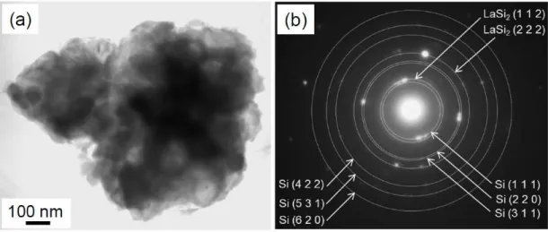
Figures 1(a) and 1(b) show a TEM image and a corresponding selected area electron diffraction (SAED) of the LaSi2/Si composite powder before the gas-deposition. The size of the observed
particle ranged from several hundred nanometers to one micrometer. By the XRD analysis, the crystalline sizes of LaSi2 and Si were estimated to be 17 and 27 nm using Scherrer equation. The
spotty SAED pattern indicates the formation of LaSi2 (ICSD No. 01-074-0230) and Si (No.
00-027-1402) with a crystalline size at least several nanometers (Fig. 1(b)). Similar SAED patterns were obtained from any area of the particles. Thus, the observed particles are secondary particles in which smaller crystallites of LaSi2 and Si are uniformly dispersed. When a thick-film electrode is
prepared by using the composite powder, it is expected that the uniformly dispersed LaSi2 improves
the electrical conductivity and the mechanical durability of the electrode [26,31].
Figure 2 shows the charge–discharge (Li insertion–extraction) curves of the first cycle for the LaSi2/Si composite thick-film electrodes to discuss the charge–discharge reactions. In all the
electrolyte except for EMI-FSA, the potential plateaus were observed at around 0.1 and 0.4 V vs. Li/Li+ on the charge and discharge curves. In conventional electrolytes using organic solvents, some researchers have reported that the charge plateau at 0.1 V originates from the phase transition from crystalline Si to Li15Si4 (Li3.75Si) [38,39] and/or to amorphous Li–Si [39,40], and that the discharge
plateau at 0.4 V is attributed to Li-extraction from these phases. In ionic liquid electrolytes, similar plateaus have been already confirmed for pure Si electrodes [18,22,30,34]. On the other hand, electrodes of LaSi2 alone showed no discharge plateau curve and much smaller discharge capacities
less than about 100–130 mA h g–1 (see Figs. S4 and S5 in supporting information). Consequently, the potential plateaus in Fig. 2 are attributed to the alloying/dealloying reactions of Li with elemental Si in the LaSi2/Si composite. In PP13-FSA electrolyte, the first coulombic efficiency stood at 61%
while the efficiencies in PP13-TFSA, EMI-TFSA, and EMI-FSA were 59%, 36%, and 7%, respectively. The low efficiencies even in case of PP13-based electrolytes are possibly attributed to a high utilization ratio of elemental Si for Li-storage. The initial charge capacity based on Li-Si alloying can be estimated to be about 1100 mA h g−1 in the PP13-FSA electrolyte from the range of Li-insertion plateau at around 0−0.2 V vs. Li/Li+. This capacity corresponds to the theoretical
capacity of this electrode (3580 mA h g−1 × 30%, ratio of elemental Si in the composite). This means
that the almost all Si in the composite is changed to Li15Si4 phase and undergoes drastic volume
changes. The resulting severe stress can not be completely relaxed. The pulverization in the first cycle, therefore, reduced the initial discharge capacities and the first Coulombic efficiencies. No obvious plateau was observed for the composite electrode in EMI-FSA. The lowest efficiency and a potential shoulder at around 0.5 V vs. Li/Li+ indicate a cathodic decomposition of EMI-FSA electrolyte during the charging. A non-conductive surface layer was observed only on the electrode surface of LaSi2 alone cycled in EMI-FSA in spite of washing the surface (Fig. S3). The surface
layer, which is presumably an organic layer formed by decomposing electrolyte, was observed for an electrode of LaSi2 alone also cycled in EMI-FSA. The PP13-TFSA electrolyte has been developed
by Sakaebe and Matsumoto [41,42] as a novel ionic liquid with an excellent electrochemical stability. Sano et al. have experimentally suggested that EMI-FSA was cathodically decomposed on Ni electrode at a potential below about 1.2–1.4 V vs. Li/Li+ to form a thicker organic surface film,
whereas PP13-TFSA formed a thinner film [43]. A noteworthy result in this study is that very high efficiencies over 98% remained after the 8th cycle in PP13-FSA electrolyte (Fig. S1).
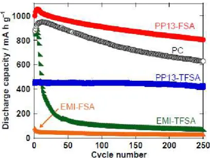
Figure 3 displays long-term cycling performances of the LaSi2/Si composite electrodes in these
ionic liquid electrolytes. The PP13-FSA electrolyte gave the electrode the most excellent performance among the four kinds of ionic liquids. The discharge capacity at the 250th cycle was 800 mAh g−1, which is about twice as large as the theoretical capacity of graphite anode. The
performance in PP13-FSA was superior to that in PC-based electrolyte [26]: the initial discharge capacity was 1000 mA h g–1 and a higher capacity retention of 80% was obtained even after a long
term of 250 cycles, whereas the retention in PC was 72%. These results clearly proved that PP13-FSA has a promising applicability as an alternative electrolyte not only to pure Si electrode [34] but also to further advanced electrodes such as LaSi2/Si composites. Another remarkable result
cycle though the initial capacity of 450 mA h g–1 was not so large compared to other electrolytes. At
the 100th cycle, the electrode exhibited a surprising retention of 100%, which has not been achieved in other silicide-based electrodes [21]. This stable cyclability was probably arisen from two reasons. One is its high stability against the cathodic decomposition. The other reason is the smaller charge–discharge capacities limited by a slower charge-transfer at the electrode/electrolyte interface. In EMI-TFSA electrolyte, the discharge capacity was quickly decreased to 150 mA h g–1 by the 50th cycle, resulting in a very poor cyclability. The EMI-FSA electrolyte delivered very small capacities of only 40 mA h g–1, which corresponds to the capacity of LaSi2 alone (Fig. S5). An organic surface
layer produced by the decomposition of electrolyte possibly prevents Li ions from transferring into the LaSi2/Si electrode in EMI-FSA.
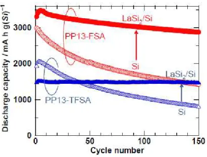
To discuss Li-insertion/extraction properties of elemental Si in the LaSi2/Si composite, the
discharge capacities of LaSi2/Si electrodes were converted to capacities per mass of elemental Si.
Figure 4 shows variation in the discharge capacities per elemental Si mass of LaSi2/Si composite
electrodes in PP13-FSA and PP13-TFSA electrolytes by the 150th cycle, comparing thick-film electrodes of elemental Si alone [34]. In both electrolytes, the cyclability was improved by changing electrodes from Si alone to LaSi2/Si composites. In particular, a drastic improvement in the
performance was recognized for the LaSi2/Si electrode in PP13-FSA electrolyte. Very large
discharge capacities of 3300 and 2570 mA h g(Si)–1 were found at the first cycle and the 150th cycles. A ratio of the capacity to the theoretical capacity (3580 mA h g–1) was as high as 78% at the 150th
cycle. This result shows that elemental Si in the composite efficiently contributes to Li-insertion/extraction even after a long-term charge–discharge owing to the promising applicability of PP13-FSA and a benefit of LaSi2 as conductive material and buffer material for the stress.
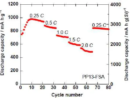
The high electrical conductivity of LaSi2 is expected to improve an anode performance of
LaSi2/Si composite electrode at high rate charge–discharge. The rate capability was evaluated at
electrode in PP13-FSA electrolyte. The capacity was gradually lowered with increasing the current rate. Large capacities of about 500 mA h g–1, which corresponds to 1700 mA h g–1 per mass of elemental Si, sustained even at a higher rate of 2.0 C (2520 mA g–1). For a novel Si-based anode with
high-rate performance, Guo et al. have recently synthesized Si-Al2O3 composite anodes on
nanopillar Cu substrate by using a magnetron sputtering, an atomic layer deposition, and a successive thermal treatment in a reductive atmosphere, and have reported that the composite anodes exhibited an excellent high-rate performance in the conventional organic electrolyte: the capacity was 1500 mA h g–1 at a rate of 2800 mA g–1 [44]. It is thus demonstrated that our LaSi2/Si thick-film electrodes
exert a comparable rate-performance to their nanopillar Si-Al2O3 anodes.
To elucidate the difference in the electrode performances obtained in PP13-FSA and PP13-TFSA, we should investigate Li-ion transfer at the interface between the electrodes and the electrolytes. Figures 6(a) and 6(b) show Nyquist plots of EIS results for the LaSi2/Si electrodes being charged at
the first cycle in PP13-TFSA and PP13-FSA. These plots are composed of a smaller semicircle in a higher-frequency side, a portion of larger semicircle in a middle-frequency side, and a slope in a lower-frequency side. From the smaller and larger semicircles, Rsf and Rct were calculated by fitting
analysis using Randles circuit. Figure 6(c) compares the calculated Rct as a function of the cycle
number. The Rct in PP13-FSA is ten times smaller than that in PP13-TFSA. The Rsf in PP13-FSA is
also 6–10 times lower than that in PP13-TFSA (Fig. S7). The same tendency has been observed for the resistances of the pure Si electrode [34]. We consider that these much lower resistances suggest a smooth Li-ion transfer at the interface, resulting in better anode performances in PP13-FSA.
4. Discussion
The mechanism of the improved performance in the ionic liquid electrolyte based on FSA anions will be here discussed in the view point of the Li-ion solvation structure with the anions and the Li-ion transfer at the electrode/electrolyte interface. Li ions are solvated by two TFSA anions to form
[Li(TFSA)2]– ion clusters [45-49]. It has been well established that Li ions prefer a tetrahedrally
4-fold coordinated structure with oxygen donor ligands: Li ions are solvated by bidentate coordination with two sulfonyl groups through the oxygen atom [45,46]. On the other hand, the solvation number of "3" has been reported for the most stable coordination structure of Li ions and FSA anions [49,50,51], though the difference in the solvation stability among the numbers of 1–3 is relatively small [51]. In the [Li(FSA)3]2– ion clusters, both monodentate and bidentate coordination
were observed for between Li ions and the sulfonyl groups [49]. The distance between Li and O in the sulfonyl groups was calculated to be 0.1820 nm and 0.1808 nm for Li-FSA and Li-TFSA [51], which is probably one reason for the lower rigidity, lower viscosity, and higher ionic conductivity of electrolyte based on FSA anions. Moreover, there is a difference in the electrostatic interaction. The negative charges on the oxygen and nitrogen atoms of the FSA are nearly identical to those of the TFSA, while the positive charges on surfer atoms of FSA are substantially larger than those of TFSA, resulting in its smaller polarizability and weaker electrostatic interaction between Li and FSA [50]. We are suggesting here that an easier desolvation is promoted at the interface between electrodes and FSA-based electrolytes because of the less rigid solvation structure of [Li(FSA)3]2– clusters with
flexible monodentate coordination. Some researchers have calculated the stability of Li-FSA and Li-TFSA clusters, consisting one Li for one FSA or TFSA, by using computational method. Tsuzuki
et al. reported that the stabilization energy of Li-FSA (–134.3 kcal mol–1) is higher than that of Li-TFSA (–137.2 kcal mol–1) [50]. Scheers et al. also have suggested that Li-FSA has a lower
bond-dissociation energy (137.9 kcal mol–1) in comparison with Li-TFSA (141.5 kcal mol–1) [51]. The differences between these energies of Li-FSA and Li-TFSA are 2.9 and 3.6 kcal mol–1. Although
the difference appears to be not so large, it should be noted that different research groups inferred the almost same results. This implies that the conformation of Li-FSA cluster is more unstable than that of Li-TFSA. The calculation results support our consideration. The easier desolvation of Li ions in FSA-based electrolytes requires a less activation energy to make Li ions insert into electrode. This is
a possible reason for the lower Rct in the FSA-based electrolyte. For the same reason, Li-insertion is
suppressed in the TFSA-based electrolyte, thereby resulting in the limited discharge capacities in case of PP13-TFSA. For more detailed consideration, we needs a calculation result for the actual coordination structure, [Li(TFSA)2]– and [Li(FSA)3]2– clusters. We therefore conclude that the easier
desolvation enables efficient electrode reactions of Li-insertion/extraction to improve significantly anode performance of the LaSi2/Si composite electrodes, in the same mechanism for electrodes of Si
alone [34]. In Fig. 4, the initial capacity of LaSi2/Si composite was lower than that of Si in
PP13-TFSA electrolyte despite utilizing LaSi2. This is probably due to slower kinetics of Li-ion
transfer at the interface, relating to formation of stable [Li(TFSA)2]– clusters. The slower kinetics
prevents LaSi2 matrix from sufficiently working as diffusion path of Li ions to Si.
The origin of the lower Rsf in the FSA-based electrolyte is related to the Li-ion transfer in a
surface layer on the electrode. There is still a controversial matter with an identification of the surface layer formed on Si-based anodes in ionic liquid electrolytes. Song et al. reported that a solid electrolyte interface (SEI) layer, consisted of organic and inorganic compounds, was formed by decomposition of Py13 cations and TFSA anions on the Si–Cu anodes [19,20]. The main components of the SEI layer are alkylated Si and ester-containing species formed by the reductive decomposition of Py13 cations, and LiF salt and Si−F bond-containing compound produced by the decomposition of TFSA anions [20]. In contrast, Yamagata and Ishikawa et al. suggested that an electric double layer, containing Li ions, cations and anions, appeared on the surface of a Si-based anode [52-55]. We do not discuss here the nature of the surface layer because it is still a debatable point. The important issue is whether Li ions can transfer in the surface layer or not. The Li ions should be firstly desolvated and should pass across the surface layer before the Li-insertion into the LaSi2/Si electrode. If the surface layer is the electric double layer, Li ions in FSA-based electrolyte
would be more easily desolvated and transferred in the layer because of the weaker electrostatic interaction between Li ions and FSA anions. When there is the stronger interaction between Li ions
and anions in TFSA-based electrolyte, the more difficult desolvation of [Li(TFSA)2]− would prevent
Li ions from passing across the electric double layer. If the surface layer is the SEI layer, we consider that an organic surface layer formed by decomposing FSA anions may be thinner, and that the thinner SEI layer allows Li ions to transfer in the layer. Consequently, PP13-FSA electrolyte is suggested to show the lower Rsf compared with PP13-TFSA electrolyte.
5. Conclusion
The composite thick-film electrodes consisted of LaSi2 and elemental Si were prepared by the
GD method, and their anode performances were investigated in four kinds of the ionic liquids of PP13-FSA, PP13-TFSA, EMI-FSA, and EMI-TFSA as Li-ion battery electrolytes. The LaSi2/Si
electrode exhibited the best performance in PP13-FSA among them including a conventional organic solvent one. The discharge capacities of the electrode at the first cycle and the 250 cycle were 1000 and 800 mAh g−1, respectively. In addition to these, the electrode showed a high-rate performance
with the capacity of 500 mA h g–1 at 2.0 C. To discuss the mechanism of the improved performance, EIS analysis was carried out for the electrodes being charged in PP13-FSA and PP13-TFSA electrolytes. The Rct and Rsf in PP13-FSA are 10 and 6–10 times lower than those in PP13-TFSA,
indicating a smoother Li-ion transfer at the electrode/electrolyte interface in PP13-FSA. We therefore concluded that the excellent performance is attributed to the higher stability of PP13 cations against the cathodic decomposition and the easier desolvation of Li ions and FSA anions at the electrode/electrolyte interface.
Acknowledgments
This work was supported in part by the Li-EAD program of the New Energy and Industrial Technology Development Organization (NEDO) of Japan. This work has been partially supported by a Grant-in-Aid for Scientific Research from the Ministry of Education, Culture, Sports, Science and
Technology (MEXT) of Japan. The authors also gratefully acknowledge Prof. K. Ichino for his kind assistance with TEM observations.
References
[1] C. J. Wen, R. A. Huggins, J. Solid State Chem., 37 (1981) 271.
[2] B. Gao, S. Sinha, L. Fleming, O. Zhou, Adv. Mater., 13 (2001) 816.
[3] T. D. Hatchard and J. R. Dahn, J. Electrochem. Soc., 151, (2004) A838.
[4] M. N. Obrovac and L. Christensen, Electrochem. Solid-State Lett., 7 (2004) A93.
[5] M. N. Obrovac and L. J. Krause, J. Electrochem. Soc., 154 (2007) A103.
[6] J. Y. Kwon, J. H. Ryu, S. M. Oh, Electrochim. Acta, 55 (2010) 8051.
[7] B. Key, M. Morcrette, J.-M. Tarascon, C. P. Grey, J. Am. Chem. Soc., 133 (2011) 503.
[8] X. H. Liu, L. Q. Zhang, L. Zhong, Y. Liu, H. Zheng, J. W. Wang, J.-H. Cho, S. A. Dayeh, S. T. Picraux, J. P. Sullivan, S. X. Mao, Z. Z. Ye, J. Y. Huang, Nano Lett., 11 (2011) 2251.
[9] X. H. Liu, H. Zheng, L. Zhong, S. Huang, K. Karki, L. Q. Zhang, Y. Liu, A. Kushima, W. T. Liang, J. W. Wang, J.-H. Cho, E. Epstein, S. A. Dayeh, S. T. Picraux, T. Zhu, J. Li, J. P. Sullivan, J. Cumings, C. Wang, S. X. Mao, Z. Z. Ye, S. Zhang, J. Y. Huang, Nano Lett., 11 (2011) 3312.
[10] X. H. Liu, L. Zhong, S. Huang, S. X. Mao, T. Zhu, J. Y. Huang, ACS Nano, 6 (2012) 1522.
[11] N. Ding, J. Xu, Y. X. Yao, G. Wegner, X. Fang, C. H. Chen, I. Lieberwirth, Solid State Ionics, 180 (2009) 222.
[12] J. Xie, N. Imanishi, T. Zhang, A. Hirano, Y. Takeda, O. Yamamoto, Mater. Chem. Phys., 120 (2010) 421.
[13] G. Zhao, Y. Meng, N. Zhang, K. Sun, Mater. Lett., 76 (2012) 55.
[15] H. Kim, C.-Y. Chou, J. G. Ekerdt, G. S. Hwang, J. Phys. Chem. C, 115 (2011) 2514.
[16] Y. Ein-Eli, B. Markovsky, D. Aurbach, Y. Carmeli, H. Yamin, S. Luski, Electrochim. Acta, 39 (1994) 2559.
[17] D. Aurbach, B. Markovsky, I. Weissman, E. Levi, Y. Ein-Eli, Electrochim. Acta, 45 (1999) 67.
[18] V. Baranchugov, E. Markevich, E. Pollak, G. Salitra, D. Aurbach, Electrochem. Commun., 9 (2007) 796.
[19] C. C. Nguyen, S.-W. Song, Electrochem. Commun., 12 (2010) 1593.
[20] C. C. Nguyen, S.-W. Woo, S.-W. Song, J. Phys. Chem. C, 116 (2012) 14764.
[21] J.-A. Choi, D.-W. Kim, Y.-S. Bae, S.-W. Song, S.-H. Hong, S.-M. Lee, Electrochim. Acta, 56 (2011) 9818.
[22] V. Chakrapani, F. Rusli, M. A. Filler, P. A. Kohl, J. Phys. Chem. C, 115 (2011) 22048.
[23] T. Sugimoto, Y. Atsumi, M. Kono, M. Kikuta, E. Ishiko, M. Yamagata, M. Ishikawa, J. Power Sources, 195 (2010) 6153.
[24] H. Sakaguchi, T. Toda, Y. Nagao, T. Esaka, Electrochem. Solid-State Lett., 10 (2007) J146.
[25] T. Iida, T. Hirono, N. Shibamura, H. Sakaguchi, Electrochemistry, 76 (2008) 644.
[26] H. Sakaguchi, T. Iida, M. Itoh, N. Shibamura, T. Hirono, IOP Conf. Series: Mater. Sci. Eng., 1 (2009) 012030.
[27] H. Usui, Y. Kashiwa, T. Iida, H. Sakaguchi, J. Power Sources, 195 (2010) 3649.
[28] H. Usui, H. Nishinami, T. Iida, H. Sakaguchi, Electrochemistry, 78 (2010) 329.
[30] H. Usui, Y. Yamamoto, K. Yoshiyama, T. Itoh, and H. Sakaguchi, J. Power Sources, 196 (2011) 3911.
[31] H. Usui, K. Meabara, K. Nakai, H. Sakaguchi, Int. J. Electrochem. Sci., 6 (2011) 2246.
[32] H. Usui, N. Uchida, H. Sakaguchi, J. Power Sources, 196 (2011) 10244.
[33] H. Usui, T. Kono, H. Sakaguchi, Int. J. Electrochem. Sci., 7 (2012) 4322.
[34] H. Usui, T. Masuda, H. Sakaguchi, Chem. Lett., 41 (2012) 521.
[35] H. Usui, Y. Kiri, H. Sakaguchi, Thin Solid Films, 520 (2012) 7006.
[36] H. Usui, N. Uchida, H. Sakaguchi, Electrochemistry, 80 (2012) 737.
[37] M. V. Bulanova, P. N. Zheltov, K. A. Meleshevich, P. A. Saltykov, G. Effenberg, J.-C. Tedenac,
J. Alloys Compd., 329 (2001) 214.
[38] Y.-M. Kang, S.-M. Lee, S.-J. Kim, G.-J. Jeong, M.-S. Sung, W.-U. Choi, S.-S. Kim,
Electrochem. Commun., 9 (2007) 959.
[39] V. L. Chevrier, J. W. Zwanziger, J. R. Dahn, J. Alloys Compd., 496 (2010) 25.
[40] M. K. Datt, P. N. Kumta, J. Power Sources, 194 (2009) 1043.
[41] H. Sakaebe, H. Matsumoto, Electrochem. Commun., 5 (2003) 594.
[42] H. Matsumoto, H. Sakaebe, K. Tatsumi, M. Kikuta, E. Ishiko, M. Kono, J. Power Sources, 160 (2006) 1308.
[43] H. Sano, H. Sakaebe, H. Matsumoto, J. Power Sources, 196 (2011) 6663.
[44] F.-F. Cao, J.-W. Deng, S. Xin, H.-X. Ji, O. G. Schmidt, L.-J. Wan, Y.-G. Guo, Adv. Finct.
[45] J.-C. Lasségues, J. Grondin, D. Talaga, Phys. Chem. Chem. Phys., 8 (2006) 5629.
[46] M. Herstedt, W. A. Henderson, M. Smirnov, L. Ducasse, L. Servant, D. Talaga, J. C. Lasségues,
J. Mol. Struct., 483 (2006)145.
[47] Y. Umebayashi, T. Mitsugi, S. Fukuda, T. Fujimori, K. Fujii, R. Kanzaki, M. Takeuchi, S.-I. Ishiguro, J. Phys. Chem. B, 111 (2007) 13028.
[48] Y. Umebayashi, H. Hamano, S. Seki, B. Minofar, K. Fujii, K. Hayamizu, S. Tsuzuki, Y. Kameda, S. Kohara, M. Watanabe, J. Phys. Chem. B, 115 (2011) 12179.
[49] T. Yamaguchi, K. Mikawa, S. Koda, N. Serizawa, S. Seki, K. Fujii, Y. Umebayashi, J. Phys.
Chem. B, 116 (2012) 7322.
[50] S. Tsuzuki, K. Hayamizu, S. Seki, J. Phys. Chem. B, 114 (2010) 16329.
[51] J. Scheers, E. Jónsson, P. Jacobsson, P. Johansson, Electrochemistry, 80 (2012) 18.
[52] M. Yamagata, Y. Matsui, N. Shiotani, K. Koga, T. Sugimoto, M. Kikuta, T. Higashizaki, M. Kono, M. Ishikawa, presented at the 62nd Annual Meeting of International Society of Electrochemistry, Niigata, Japan, 2011.
[53] M. Yamagata, K. Koga, Y. Matsui, S. Nishishita, T. Sugimoto, M. Kikuta, T. Higashizaki, M. Kono, M. Ishikawa, Abstract P3-332, presented at the 16th International Meeting on Lithium Battery, Jeju, Korea, 2012.
[54] M. Ishikawa, M. Yamagata, Abstract 1210, presented at the Pacific Rim Meeting on Electrochemical and Solid-state Science 2012, Honolulu, Hawaii, 2012.
[55] K. Koga, T. Sugimoto, M. Kikuta, T. Higashizaki, M. Kono, M. Yamagata, M. Ishikawa, Abstract 1222, presented at the Pacific Rim Meeting on Electrochemical and Solid-state Science
Figure 1. (a) TEM image of typical LaSi2/Si composite particle as source material powder for GD,
Figure 2. Initial charge–discharge curves of LaSi2/Si composite thick-film electrodes in ionic liquid
electrolytes consisted of cations, N-methyl-N-propylpiperidinium (PP13) or 1-ethyl-3-methylimidazolium (EMI), and anions of bis(fluorosulfonyl)amide (FSA) or bis(trifluoromethanesulfonyl)amide (TFSA).
Figure 3. Cycling performances of LaSi2/Si composite thick-film electrodes. As a reference of
conventional organic solvent electrolyte, discharge (Li-extraction) capacities in PC were also plotted in the figure.
Figure 4. Cycling performances of LaSi2/Si composite electrodes in PP13-FSA and PP13-TFSA
electrolytes, comparing thick-film electrodes of Si alone. To discuss Li-storage capability of elemental Si in the LaSi2/Si composite, the discharge capacities of LaSi2/Si electrodes were
Figure 5. Rate performance of LaSi2/Si composite electrode in PP13-FSA. The current density was
varied from 315 mA g–1 (0.25 C) to 2520 mA g–1 (2.0 C). The right y axis indicates the capacity per
Figure 6. Nyquist plots of LaSi2/Si composite electrodes charged at the first cycle in (a) PP13-TFSA
and (b) PP13-FSA. The dashed lines indicate fitting results calculated by using Randles circuit. (c) Variation in charge-transfer resistance (Rct) of LaSi2/Si composite electrodes.
Figure captions
Figure 1. (a) TEM image of typical LaSi2/Si composite particle as source material powder for GD,
and (b) corresponding SAED pattern.
Figure 2. Initial charge–discharge curves of LaSi2/Si composite thick-film electrodes in ionic liquid
electrolytes consisted of cations, N-methyl-N-propylpiperidinium (PP13) or 1-ethyl-3-methylimidazolium (EMI), and anions of bis(fluorosulfonyl)amide (FSA) or bis(trifluoromethanesulfonyl)amide (TFSA).
Figure 3. Cycling performances of LaSi2/Si composite thick-film electrodes. As a reference of
conventional organic solvent electrolyte, discharge (Li-extraction) capacities in PC were also plotted in the figure.
Figure 4. Cycling performances of LaSi2/Si composite electrodes in PP13-FSA and PP13-TFSA
electrolytes, comparing thick-film electrodes of Si alone. To discuss Li-storage capability of elemental Si in the LaSi2/Si composite, the discharge capacities of LaSi2/Si electrodes were
converted to capacities per mass of elemental Si.
Figure 5. Rate performance of LaSi2/Si composite electrode in PP13-FSA. The current density was
varied from 315 mA g–1 (0.25 C) to 2520 mA g–1 (2.0 C). The right y axis indicates the capacity per
Figure 6. Nyquist plots of LaSi2/Si composite electrodes charged at the first cycle in (a) PP13-TFSA
and (b) PP13-FSA. The dashed lines indicate fitting results calculated by using Randles circuit. (c) Variation in charge-transfer resistance (Rct) of LaSi2/Si composite electrodes.