Thesis for Doctor of Engineering
Effects of Cold Atmospheric Pressure Plasma Jet on the
Viability of Bacillus subtilis Endospores
Vinita Sharma
2013
Department of Production and Science and Technology,
Graduate school of Engineering, Gunma University
Table of Contents
Table of content i
CHAPTER 1 GENERAL INTRODUCTION
1.1 Background Research 1
1.2 Requirements for a Good Sterilization method 2
1.3 Objective of this Study 3
1.4 Novelty of my Research 3
1.5 Structure of the Thesis 4
1.6 References 5
1.2 Plasma 5
1.2.1 Classification of Plasma 6
1.2.1.1 Local Thermodynamic Equilibrium Plasma or Thermal Plasma (LTE plasmas) 6 1.2.1.2 Non Local Thermodynamic Equilibrium Plasma or Thermal Plasma (Non LTE plasmas) 7
1.2.2 Atmospheric Pressure Plasma 8
1.2.3 Sources and the Mode of Atmospheric Pressure Plasma Discharges 9
1.2.3.1 Dielectric Barrier Discharges 9
1.2.3.2 Filamentary dielectric –barrier discharges 11
1.2.3.3 Diffuse Dielectric Barrier Discharges (Glow Discharges) 12
1.2.4 Electrical and Optical Characterization 13
1.2.5 Mechanism and Applications of Atmospheric Pressure Cold Plasma Jet 14
1.2.6 References 16
1.3. Bacterial Endospores 20
1.3.1 Introduction of bacteria and endospore 20
1.3.2 Sporulation 20
1.3.3 Bacterial Endospores or spores 22
1.3.3.1 Spore Coat 23
1.3.3.2 Cortex 23
1.3.3.3 Core 25
1.3.3.4 Formation of Spore Layers 26
1.3.4 Conclusion 27
1.3.5 References 28
CHAPTER2 ELECTRICAL AND OPTICAL CHARACTERIZATION OF COLD ATMOSPHERIC PRESSURE PLASMA TORCH (CAPPLAT – 9Ne) AND THE EFFECT OF N2 GAS ADDITION ON
ARGON PLASMA JET
2.1 Introduction 32
2.2 Experimental Set Up and Methods 33
2.2.1 Plasma Device 33
2.2.2 Electrical Measurements 37
2.2.3 Optical Emission Spectroscopic Measurements 37
2.3 Result and Discussion 38
2.3.2 OES Characterization of Ar Plasma Jet and the Effects of the Additive Gas (N2) 44
2.4 Application of Plasma Torch 49
2.5 Conclusion 51
2.6 References 52
CHAPTER 3 ELECTRICAL AND OPTICAL CHARACTERIZATION OF COLD ATMOSPHERIC PRESSURE PLASMA TORCH (CAPPLAT) THE BASIC UNIT AND THE EFFECTS OF N2 GAS,
O2 GAS ANDH2O2 ON ARGON PLASMA JET
3.1 Introduction 54
3.2 Experimental Set Up and Methods 55
3.2.1 Plasma Device (Basic CAPPLAT) 55
3.2.2 Electrical Measurements 57
3.2.3 Optical Emission Spectroscopic Measurements 57
3.2.4 Addition of Gases to the Plasma Jet (Direct Injection Mode) 57 3.2.5 Effects of Plasma Jet from CAPPLAT on the Viability of Endospores 59
3.3 Results and Discussion 59
3.3.1.1 Electrical Characterization of Ar Plasma Jet from CAPPLAT and the Effect of N2 Addition
59
3.3.1.2 Effects of O2 and H2O2 Additions on the Electrical Characterization of Ar-N2 Plasma jet
Obtained from CAPPLAT 64
3.3.2.1 OES Characterization of Ar Plasma Jet and the Effects of N2 Addition 65
3.3.2.2 Effects of the Addition of O2 & H2O2 on the OES Characterization of Ar-N2 Plasma Jet 67
3.3.2.3 Effect of the Ar-N2-O2 Plasma Jet and Ar-N2- H2O2 Plasma Jet on the Viability of Bacillus
subtilis Endospores 71
3.4 Conclusion 71
3.5 References 72
CHAPTER 4 EFFECTS OF COLD ATMOSPHERIC PRESSURE PLASMA TORCH (CAPPLAT) VIABILITY OF BACILLUS ENDOSPORES
4.1 Introduction 74
4.2 Experimental Set up and Methods 76
4.2.1 Plasma Device and Electrical and Optical Emission Spectroscopic Measurements 76 4.2.2 Culture Condition and Isolation of Endospores 77 4.2.3 Air Dried Spore Agar Disc for Plasma Treatment 78 4.2.4 Measurement of of Released DPA (Dipicolinic acid or Pyridine-2, 6 – dicarboxylic acid)
79
4.3 Results and Discussion 80
4.3.1 Electrical and Optical Characterization 80
4.3.2 Effects of Plasma Exposure on Endospores 81
4.3.2.1 The Viability Check of Endospores by CFU (colony Forming Unit) Counting 81 4.3.2.2 Estimation of DPA to confirm Irreversible Cortex Lysis 85
4.3.2.3 Visual Inspection by SEM Micrographs 88
4.4 Mechanism of Endospore Inactivation 89
4.5 Conclusion 96
Chapter 5 EFFECTS OF COLD ATMOSPHERIC PRESSURE PLASMA TORCH
(CAPPLAT) ON THE VIABILITY OF BACILLUS ENDOSPORES AND THE
ENHANCEMENT OF THE STERILIZATION EFFICIENCY OF PLASMA JET FROM
THE CAPPLAT
5.1 Introduction 102
5.2 Experimental Set up and Methods 103
5.2.1 Plasma Device 103
5.2.2 Electrical Measurements 103
5.2.3 Optical Emission Spectroscopic Measurements 103
5.2.4 Addition of Gases to the Plasma Jet (Direct Injection Mode 103 5.2.5 Effect of the Plasma Jet from CAPPLAT on the Viability of Endospores 104
5.3 Results and Discussion 104
5.3.1 Electrical Characterization of Ar Plasma Jet Obtained from CAPPLAT and the Effects of
Addition of N2, O2 and H2O2 104
5.3.2 OES Characterization of Ae Plasma Discharge (Jet) and the Effects of the Addition of N2, O2
and H2O2 104
5.3.3 Effects of Ar-N2 Plasma Jet from CAPPLAT on the Viability of Endospores 104
5.3.4 Effects of Ar- N2- O2 Plasma Jet on the Viability of Endospores 108
5.3.5 Effects of Ar- N2- H2O2 Plasma Jet on the Viability of Endospores 111
5.4 Conclusion 116
5.5 References 117
Chapter 6 Summary
119List of Publications 122 Acknowledgements 123
Chapter 1 - General Introduction
1.1 Background Research
Bacteria are ubiquitous and inevitable part of our existence. They are the most abundant and ancient form of the life. They immensely support the existence of the life but on the other hand they put our lives and money at stake. They often make the base of the food webs as they break down dead organic matter into simpler consumable forms for the producers or other microorganisms. They help certain plants (legumes) to convert N2 gas into proteins (nitrogen fixation). They have
symbiotic relationships with lots of animals including human beings. They are indispensable in our food industry. Sometimes, they are used in combination with yeasts and molds, particularly for fermentation based processes. They are used to make therapeutic drugs like insulin, vitamins etc.. Certain actinomycetes (a group of bacteria), make antibiotics like streptomycin and nocardicin but some pathogenic bacteria like Streptococcus, Staphylococcus, E. coli, Leptospira, Erwinia
amylovora etc. cause some life threatening diseases to human beings, livestock and plants. They are
used for industrial waste processing and for bioremediation. The ability of bacteria to digest hydrocarbons in petroleum is used to clean up oil spills. Researchers believe 48,000 deaths could have been prevented and $8.1 billion dollars could have been saved in the United States, if patients hadn't gotten infections after being admitted to a hospital [1] and most of the infections are caused by bacteria (endospores). To ensure the safety of our heath, food products, medical equipment, packaging or aseptic conditions in the laboratories, we need to eradicate bacteria from that particular environment. To do so, we need to sterilize things. Sterilization is a little bit more than just removing bacteria. Sterilization is the process by which all living cells, viable spores, viruses or viroids and even prions are either destroyed or removed from an object or a habitat.
There are several methods to achieve a high level of sterilization. According to FDA (U.S. Food and Drug Administration), 1997, a sterilization device or method should meet the acceptable sterility assurance level (SAL) which is 106 i.e. one chance in a million to be contaminated. There are several physical and chemical methods of sterilization. Physical methods are like thermal inactivation, filtration, and radiation. The chemical methods, achieve sterilization with the help of chemicals like H2O2, ethylene oxide, peracetic acid, beta propiolactone, alcohol, chlorine and its
oxides and aldehydes etc.. These methods have their own merits and demerits. Thermal methods are effective and economic but they need higher temperature which makes them unsuitable for heat liable substrates. Filtration just filters out microorganisms but doesn’t kill them. Radiation methods are expensive, need special operating conditions. Gamma radiation affects the bulk properties of the polymers being treated, as it breaks bonds and cross-linked chains within the volume of the material [3]. In late 1980s, there were strict regulations on the ethylene oxide and radiation sterilization in Japan [2]. Chemical methods are effective but they are not environment or people friendly. They require long sterilization time and sometimes, much longer venting time after sterilization. Most widely used ethylene oxide, is carcinogenic and its residues get absorbed on the materials [4, 5]. To overcome these problems, some new methods like high pressure sterilization, pressure assisted thermal sterilization, supercritical fluid sterilization; pulsed electric field sterilization etc. came into existence. Although they are better than the traditional sterilization methods in some ways but still they have their own limitations like in some cases, still, the working temperature is too high for heat sensitive materials. The main problem with these methods is their effectiveness against endospores. They are very effective against vegetative cells. Efforts are being made to make them more effective but still they are not the perfect solutions for perfect sterilization.
1.2 Requirements for a Good Sterilization Process
A good sterilization process should have rapid microbicidal activity, compatibility with surfaces being treated, noncorrosive, easily removable from the surface with the least residue,
reliable, economical and no adverse effects on the quality of the product. So, far no method fulfills all of these mentioned requirements. So, we are in an urgent need to have a sophisticated method of sterilization that fulfills all of the mentioned requirements.
Cold atmospheric pressure plasma could be a solution of this problem. As it works at low temperature, no chemical residues, safe and highly energetic to attain a higher level of sterilization in a shorter period of time, very low penetration power so it doesn’t affect the bulk properties of the substrate. There is absolutely no need of post sterilization venting time. It works at atmospheric pressure so it’s comparatively less expensive and easy to operate.
1.3 Objective of this Study
First of all, we would like to characterize our own designed plasma jet generating device, electrically and optically. We call this device “Cold Atmospheric Pressure Plasma Torch – 9 Ne” (CAPPLAT- 9Ne). This device is a commercial unit. We would like to compare it with CAPPLAT the basic unit. We would like to figure out the mechanism of plasma generation.
Then we would like to use the plasma jet generated by CAPPLAT- 9Ne to inactivate a
Bacillus subtilis endospore population of 1.0X10⁷ to 1.4X10⁷ endospores/ml. We decided to work on 1.0X10⁷ to1.4X107 endospores/ml because it is slightly higher than the acceptable sterility assurance level or SAL (106). We would like to figure out the mechanism of endospore inactivation.
We would repeat the same experiment with the CAPPLAT the basic unit to compare the effectiveness of our commercial unit (CAPPLAT- 9Ne) as a sterilization tool. We would add some oxidants to the plasma jet to see if we could enhance the sterilization efficacy.
1.4 Novelty of this Research
CAPPLAT- 9 Ne the commercial unit is our own designed plasma generating device. Nobody has ever used it before for any research purposes. CAPPLAT the basic unit was also never used for
any bio-applications. There is not enough work on cold atmospheric pressure plasma to propose a well explained mechanism of bacterial inactivation. More work has been done on cold plasma at reduced pressure. The respective roles of UV photons and radicals at reduced pressure are already well understood [6–9], which is not the case yet at atmosphericpressure [10, 11].
1.5. Structure of the thesis
This thesis will have five chapters. Chapter 1 will be a general introduction. Chapter 2 will be discussing about CAPPLAT- 9Ne in detail. Chapter 3 will have information about CAPPLAT the basic unit and addition of oxidants (O2 and H2O2) to the plasma jet. Chapter 4 will cover all of the
aspects of our experiments about endospores. Chapter 5 will be devoted to the see the effect of CAPPLAT the basic unit on Bacillus subtilis endospores. We will also see the effect of the plasma on the viability of the endospores after the addition of oxidants (O2 and H2O2) and finally, Chapter
6 will summarize the whole work.
Figure 1.1Research Outline
Effects of Cold Atmospheric Pressure Plasma Jet on the Viability
of Bacillus subtilis Endospore
Electrical and Optical Characterization of
Cold Atmospheric Pressure Plasma Torch (CAPPLAT – 9Ne) the Commercial unit and the Effects of N2 gas on
Argon Plasma Jet (Chapter 2)
Electrical and Optical Characterization of Cold
Atmospheric Pressure Plasma Torch (CAPPLAT)
the Basic Unit and the Effects of Addition of N2 Gas, O2 Gas and H2O2 on
Argon Plasma Jet
(Chapter 3) Introduction (Chapter 1) Effect of Cold Atmospheric Pressure Plasma Torch (CAPPLAT- 9Ne) on the viability of Bacillus subtilis Endospores (Chapter 4) Effect of Cold Atmospheric Pressure Plasma Torch (CAPPLAT)
the Basic Unit on Endospore Inactivation and the Enhancement of the
Sterilization Efficiency of Plasma
Jet from the CAPPLAT (Chapter 5)
1.6 References
[1] Miriam Falco. CNN Medical News Managing Editor. 2010.
[2] Taniguchi M., Suzuki H, Sato M, and Kobayashi T. Sterilization of plasma powder by treatment with supercritical carbon dioxide. Agric. Biol. Chem., 51 – 3425, 1987.
[3] Henn GG, Birkinshaw C, Buggy M, and Jones E. A comparison study of the effects of gamma-irradiation and ethylene oxide sterilization on the properties of compression moulded poly-D-L-lactide. J. Mat. Sci.—Mater. Med. 7, 591–595, 1996
[4] Holyoak GR, Wang S, Liu Y, and Bunch TD. Toxic effects of ethylene oxide residues on bovine embryos in vitro. Toxicology, 108, 33–38, 1996.
[5] Zhang YZ, Bjursten LM, Freij-Larson C, Kober M, and Wessle´n B. Tissue response to commercial silicone and polyurethane elastomers after different sterilization procedures. Biomaterials, 17, 2265–2272, 1996
[6] Moisan M, Barbeau J, and Pelletier J. Le vide: Sci. Tech. Appl., 299, 15–28, 2001
[7] Moisan M, Barbeau J, Moreau S, Pelletier J, Tabrizian M, and Yahia, L.H. Int. J. Pharm., 226, 1–21, 2001.
[8] Moisan M, Barbeau J, Pelletier J, Philip N, and Saoudi B. 13th Int. Coll. Plasma Processes (SFV), Antibes; (Mai 2001). Le vide: Sci. Tech. Appl. Numéro spécial: Actes de Colloque, pp. 12–18, 2001.
[9] Philip N, Saoudi B, Barbeau J, Moisan M, and Pelletier J. 13th Int. Coll. Plasma Processes (SFV), Antibes; (Mai 2001). Le vide: Sci. Tech. Appl. Numéro spécial: Actes de Colloque, pp. 245–247, 2001.
[10] Laroussi M. IEEE Trans. Plasma Sci. 24, 1188–1191, 1996.
[11] Hermann H W, Henins I, Park J and Selwyn G S. Physics Plasmas 6, 2284–2289, 1999.
1.2 Plasma
Plasma is an ionized gas which contains free electrons, ions, radicals and highly excited neutral and charged species. The term plasma was introduced by Irving Langmuir. Plasma can be
created by providing energy to a neutral gas in order to ionize it. The source of energy could be thermal, electric and electromagnetic radiations. Plasmas are chemically and physically very active media in spite of their quasi neutral status. Basic idea of plasma production, composition, types is summarized in Figure 1.2.1.
David A. Frank-Kamenezki used the term “the fourth state of matter” for the plasma. 99% of our Universe including stars, nebulae, interstellar space are consists of plasma [1]. Our Solar System is also filled with plasma in the form of the solar winds. On the earth besides laboratories we can see plasma in our daily lives as lightning, fluorescent lamps, plasma TV etc.. In advanced engineering and technology, we use plasmas in welding, switching, surface activation, chemical conversion, environment protection, melting, incineration and partial discharges in electrical engineering etc..
1.2.1 Classification of Plasma
Depending on the type of energy supply and the amount of energy transferred to the plasma, the properties of plasma change in terms of temperature and electron density [1, 2]. Atmospheric plasmas can be divided into two categories – local thermodynamic equilibrium plasma (LTE
plasma) or thermal plasma and non- local thermodynamic equilibrium plasma (Non LTE plasma) or
cold plasma [2, 3].
1.2.1.1 Local Thermodynamic Equilibrium Plasma or Thermal Plasma (LTE plasmas)
In LTE plasmas, transitions and chemical reactions are controlled by collisions and radiative processes [4]. Collisions are micro-reversible i.e. excitations is accompanied with de-excitation; Ionization is accompanied with recombination and vice versa to maintain the kinetic balance [5]. To have LTE, it is required that the local gradients of plasma properties like temperature, electron density, and thermal conductivity should be low enough to let a particle in the plasma reach the equilibrium: diffusion time must be similar or higher than the time, the particle needs to reach the equilibrium [2]. Inelastic collisions between electrons and heavy particles create active species in plasma whereas elastic collisions heat up the heavy particles and electrons lose their energy. That is why for local thermodynamic equilibrium plasma or thermal plasma the temperature of electrons (Te), temperature of heavy particles (Th) and the overall temperature of the gas (Tg) are almost the
same i.e. Te Th Tg≈ 10,000K, as we see in arc discharges [1].
1.2.1.2 Non Local Thermodynamic Equilibrium Plasma or Thermal Plasma (Non LTE plasmas)
In LTE plasma, the temperature of gas, heavy particles and electrons are the same but in Non LTE plasmas the temperature of electrons (Te) is much higher than the temperature of heavy
particles (Th) but because of huge mass difference between heavy particles and electrons, the
temperature of plasma or the temperature of the gas (Tg) is governed by the temperature of heavy
particles i.e. Te>>Th Tg. The deviation of Non-LTE plasmas from Boltzman distribution for the
density of electrons could be explained by the fact that the electron induced de-excitation rate of atoms is lower than the corresponding electron induced excitation rate because of significant radiative de-excitation rate [5]. Electrons move very fast whereas heavy particles are almost static in comparison to the electrons so unlike LTE plasmas, non LTE plasmas have local gradients of plasma properties like temperature, electron density, and thermal conductivity should be high enough and diffusion time should be less than the time, the particles need to reach the equilibrium. In this scenario, we will have non-equilibrium plasma. Inelastic collisions between electrons and
heavy particles are responsible for plasma chemistry whereas only a few elastic collisions heat up the heavy particles slightly (Th ≈ 300 - 1000 K) that is why electrons remain highly energetic (Te≈
10,000- 100,000 K), as we see in glow discharges [1]. That is why overall temperature of the plasma remains low (cold plasma).
1.2.2 Atmospheric Pressure Plasmas
Figure1.2.2 shows the relationship between the temperature and the pressure and their effects on the nature of the plasma [7]. As we increase the pressure, temperatures of electrons and heavy particles also change and the whole plasma system moves from non-local thermodynamic equilibrium (cold plasma) to Local thermodynamic equilibrium (thermal plasma) or we can say the transition from glow discharge to arc discharge. In the low pressure zone (10⁻3 to 10⁻1
Torr), gas temperature (Tg is much lower than the electron temperature (Te) (Figure1.2.2).
In low pressure zone, only inelastic collisions between electrons and heavy particles are responsible for the plasma chemistry which cannot increase the temperature of heavy particles or
Figure1.2.2 Relationship between the temperature and the pressure, for equilibrium and non-equilibrium plasmas (Taken from the reference 7)
the plasmas. As the pressure keeps increasing, difference between the temperature of electrons and heavy particles keeps decreasing and finally, both processes inelastic collisions for plasma chemistry and elastic collisions to increase the temperature of heavy particles get intensified and plasma approaches close to the thermodynamic equilibrium. At atmospheric pressure plasma is almost LTE plasma.
High power density induces LTE plasma (arc plasmas) and low density feeding power or pulsed power supply induces Non-LTE plasmas (homogeneous plasmas) as short pulse durations prevent from attaining equilibrium [1, 4]. In an atmospheric plasma jet, plasma core is in thermodynamic equilibrium whereas peripheral one is in non-thermodynamic equilibrium [1, 4].
1.2.3 Sources and the Mode of Atmospheric Pressure Plasma Discharges
To produce atmospheric plasma, different types of sources with different types of frequencies can be used. These sources can mainly be divided into three types of sources namely DC (direct current) discharges, low frequency discharges in continuous or pulsed mode, RF (radio wave frequency) discharges and microwave discharges. In DC low frequency discharges with continuous working mode, we can have arc plasma torches [24] but if we have pulsed working mode we can have dielectric barrier discharges. Depending on other parameters, these discharges can be filamentary or glow [25, 26]. RF discharges can also work with low and high power supply [27, 28 & 29]. Among these different types of discharges, DBD discharges are most widely used.
1.2.3.1 Dielectric Barrier Discharges
Dielectric barrier discharge or silent discharge works on higher pressure [8, 9] about 10-1000 kPa. Dielectric barrier discharge is a special type of AC or RF discharge with the frequency in the range of 1 to 20 kHz. The discharge can be ignited by sinusoidal power source [10] or pulsed power source [11]. The dielectric barrier is placed between two electrodes. The electrodes can be planner or concentric, as shown in Figure1.2.3.
Dielectric barriers can touch one or both or not any electrodes (Figure1.2.3). Normally there is a distance of few millimeters in case of dielectric barrier discharges but there is no gap in case of surface discharges. Sometimes, all of the space between electrodes is packed with dielectric substances (Figure1.2.4).
Figure1.2.3 Parallel and concentric configurations of dielectric barrier discharge; A, B, C show the arrangement for parallel electrodes; D shows the arrangement for
concentric electrodes (Taken from references 30)
Figure1.2.4 showing different types of configurations of electrodes without spaces between electrodes (Taken from reference 6)
A
B C
Both filamentary and glow discharge modes are observed at atmospheric pressure. The nature of discharge depends on the working gas or the mixture of gases, dielectric barrier and the operating conditions [14].
1.2.3.2 Filamentary Dielectric Barrier Discharges.
In most of the cases, DBD has multi-steamer mode of operation with the formation of microdischarges [13] which subsequently change into visible filaments. They strike at the same place when the polarity changes because of the memory effect and these microdischarges look like continuous filaments.
When a high voltage is applied across the electrodes, the background electrons or knocked out electrons from the heavy particles, start multiple avalanches which are governed by Townsend ionization coefficient α which is the function of reduced electric field E/n where E is electric field and n is the gas density. The charge accumulation in avalanches because of strong applied electric field creates local electric fields which allow streamers grow. There is a transition from avalanches to streamers and then streamers propagate within 10 ns from the anode to the cathode in the direction, opposite to the avalanches, with a very high speed (about 108 cm/s, an order of magnitude faster than the avalanches) to cover the distance between electrodes in nanoseconds [15]. Streamers are local ionization waves usually move from the anode to the cathode (Figure1.2.5).
Figure1.2.5 Evolution of electron avalanche in discharge gap, showing avalanche development, avalanche-to-streamer transition, and streamer propagation (Taken from reference 15)
Streamers are formed at the same place because of the memory effect of the charge deposition on the dielectric surface and the residual charges from the previous cycle. The electrons in conducting channels dissipate rapidly while the heavy ions stay for several microseconds [15]. The electron accumulation on dielectric barrier prevents further avalanches and streamer formation until the change in polarity.
1.2.3.3 Diffuse Dielectric-Barrier Discharges (Glow Discharge)
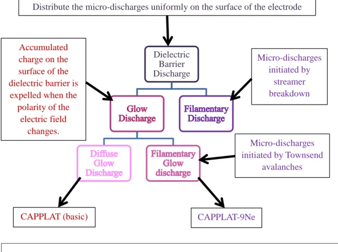
The glow mode of DBD could be uniform or filamentary. In case of DBD glow discharge, the filaments are formed because of avalanches rather than streamers. In glow discharge, filaments are initiated by Townsend ionization whereas filamentary dielectric barrier discharge is because of streamer breakdown [16, 17]. S. Okazaki introduced the term APGD (atmospheric pressure glow discharge). Okazaki and her co-workers obtained glow barrier discharge at 50 Hz sinusoidal feeding voltage with pure He, N2 and air without any additive gas. They used ceramic dielectric [18, 19, and
20]. Plasma density in micro discharges is much higher than the surroundings. The locations of microdischarge formations can be considered as active locations on whole DBD. As a result of microdischarges, lots of energy dissipates which decreases the temperature but surrounding local temperature still stays high. Microdischarges or filaments strike at the same place. Although these areas and discharge volumes are small but if the temperature difference persists for a long time at the same place, it will make the effect of the plasma non-uniform on the substrate. So, it is very necessary to have uniform glow discharge to have a uniform effect on the surface of the substrate. To have glow discharge or to prevent filamentation, we should have enough pre-ionization electron density, which can be achieved by sufficient pre-ionization by x-rays, electron beams or by double-discharge techniques, [21].The higher pre-ionization electron density helps to overlap and coalesce the primary avalanche heads to smooth out the space charge field gradient which will otherwise make streamers. Brenning et al. [22] pointed out the importance of an additional minimum pre-ionization rate just prior to and during breakdown. Impurities, gas additives, the presence of metastables and residual ions also affect glow discharges. The densities of residual species from the
previous half period that can initiate the diffuse discharge in the next half cycle depend on the repetition frequency. Therefore, the feeding voltage frequency plays an important role in the transition to the diffuse mode. Some dielectric materials can trap considerable amounts of charges uniformly on the surface. When the electric field changes its polarity, the charge carriers are expelled from the surface and initiate a diffuse discharge [23]. By feeding additive gas into working gas can also help to attain glow discharge by the process of quenching.
1.2.4 Electrical and Optical Characterization
To understand DBD discharges and to ascertain that the discharges are filamentary or glow discharges, electrical characterization of plasma is indispensable. It helps us to understand the discharge voltage, discharge current, and the impedance of the entire load not just the plasma discharge. Nature of the current waveform and pulse width can give clues about the nature of the discharge as the spikey current waveform shows filamentary discharge whereas a smooth waveform is the representation of glow discharge besides that filamentary current has narrower pulse width than the glow discharge current. In dielectric barrier discharges, it actually acts like a combination of two capacitors, one is the dielectric barrier and the other one is the gap between electrodes which also acts like a capacitor but in case of surface discharge there is no gap between electrodes and DBD. So, an equivalent R-C parallel circuit (Figure1.2.6) can be used for electrical characterization where C represents capacitance of silicon dielectric substance used between two concentric electrodes and R represents resistance of the discharge.
A1
A2
C
R
To record waveforms, we used oscilloscope. Changes in nominal applied voltage on current can also give us the idea about changes in electron density in current. The quantity of charge transfer is mainly determined by the categories of dielectric and the width of gap spacing [30]. According to the above circuit total current (A1) will be the sum of capacitive current (A2) and
discharge current. We can measure total current and capacitive current then using the above circuit discharge current (A1- A2) can be calculated.
Plasma is quasi-neutral in nature. It is the mixture of highly active species which are responsible for the effects of plasma on substrates. To confirm the presence of different active species and to understand the mechanism of the formation of the active species, optical characterization of plasma is necessary. Optical emission spectroscopy (OES) is well known as non-invasive and non-disturbing technique for plasma diagnostics [32-36]. In plasmas, excitation and de-excitation processes keep going on. When excited molecules de-excite they emit radiations and the optic fiber probe of optical emission spectroscopy captures these emission radiations of active species which are analyzed and the intensity of emission radiation is measured as the function of the wavelength. As all of the transitions take place at very specific wavelengths, so, these spectrum help us to identify different active species. Using a special OES simulation program the rotational and vibrational temperature of excited molecules can be measured [37]. For equilibrium plasmas, the electron temperature can be derived whereas for non-equilibrium plasmas excitation temperature can be measured [37].
1.2.5 Mechanism and Applications of Atmospheric Pressure Cold Plasma Jet
Plasma jet producing devices consist of two concentric electrodes. There are several possible configurations for electrodes like one powered and one grounded electrode, without grounded electrode, combination of two tubes where inner tube is streamed with an inert gas for charge ignition and outer for precursor, with two coaxial electrodes with dielectric in between and plasma jets with an inner RF driven needle electrode, with and without grounded ring electrode [38]. The
gas discharge can be ignited by RF power or by high voltage pulsed power. The plasma produced between the electrodes is expanded outside of the electrode configuration in the form of plasma jet because of the pressure of the air flow from the above as shown in Figure 1.2.7. Between the electrodes, we have active plasma which is rich in active species. In plasma effluents (Jet) as shown in Figure 1.2.8, the density of charged species is lower. It has mainly long lived species and free electrons which are responsible for the plasma chemistry on substrates.
Plasma jets are widely used in plasma processing applications. It is particularly useful to complex shaped substrates. They are used for surface treatments like surface cleaning, surface etching, and surface activation. They are also used for surface coating. It is really important, because the surface coating happens without any changes in the intrinsic bulk properties. There are two types of surface coating – air plasma spray (APS) coating and plasma enhanced chemical vapor deposition. Although the mechanism for lots of processes is not clear yet, but in recent years lots of progress have been made and it seems like for surface cleaning metastable energetic species are responsible [38, 39]. For etching, lots of parameters besides plasma composition like substrate nature, power, and gas flow play an important role. For surface activation, active species in plasma
Nozzle Dielectric barrier Plasma jet Grounded electrode High voltage Gas Substrate
Figure1.2.7 – Schematic representation of plasma jet principal
change the surface energy and make it ready for grafting. Plasma jets have also been used for sterilization or bacterial inactivation.
1.2.6 References
[1] Tendero C, Tixier C, and Tristant P. Spectrochimica Acta Part B 61, 2, 2006.
[2] Boulos MI, Fauchais P, and Pfender E. Thermal plasmas: Fundamental and Applications. Volume 1, plenum Press, New York, ISBN: 0-306-44607-3, 452, 1994.
[3] Massines F, Ségur P, Gherardi N, Khamphan C, and Ricard A. Surf. and Coat Techn., 174-175:8, 2003.
[4] Fei Xiaomeng, Kuroda Shin-ichi, Kondo Yuki, Mori Tamio, and Hosoi Katsuhiko. Comparison of High-density Polyethylene Surface Treatment Using Two Types of Cold Atmospheric Pressure Ar Plasma Jets, 2010.
[5] Moisan M, Calzada MD, Gamero A, and Sola A. Experimental investigation and
characterization of the departure from local thermodynamic equilibrium along a surface-wave-sustained discharge at atmospheric pressure, J. Appl. Phys. 80 (1) 46– 55, 1996.
[6] Wagner Hans-Erich and Brandenburg Ronny. Atmospheric Pressure Plasmas. Plasma Applications in Material Science PAMS-2011.
[7] Roth JR. Industrial Plasma Engineering. Vol.1: principles, IOP publishing Ltd. 1995. [8] Eliasson B, and Kogelschatz U. IEEE Trans. Plasma Sci.19309, 1991.
[9] Kogelschatz U, Eliasson B, and Ehli W. J. PhysiqueIV7C4 47, 1995.
[10] Jimenez C, Martin S, Gherardi N, Durand J, Cot D, and Massines F. Etude de la formation de nano et micro particules dans une de´charge a` la pression atmosphe´rique, Mate´riaux 2002:
de la conception a` la mise en oeuvre, 21– 25 Octobre 2002, Tours, France, Tours VINCI, Tours , CD-ROM, 2002.
[11] Salge J. Plasma-assisted depositon at atmospheric pressure, Surf. Coat. Technol. 80, 1 –7, 1996.
[12] Kogelschatz U. Atmospheric pressure plasma technology. Plasma Phys. Control. Fusion 46 B63–B75, 2004.
[13] Kogelschatz U. Dielectric-barrier Discharges: Their History, Discharge Physics, and Industrial Applications. Plasma Chemistry and Plasma Processing, Vol. 23, No. 1, 2003. [14] Kogelschatz U. For a recent review of the diverse phenomenon in barrier discharges, see:
IEEE Trans. Plasma Sci. 30 (4), 1400–1408, 2002.
[15] Chirokov A, Gutsol A, and Fridman A. Atmospheric pressure plasma of dielectric barrier discharges. Pure and Applied Chemistry, 77(2), pp.487–495, 2005.
[16] Brauer I, Punset C, Purwins HG, and Boeuf JP. J. Appl. Phys. 85 (11), 7569–7572, 1999. [17] Müller I, Punset C, Ammelt E, Purwins HG, and Boeuf JP. IEEE Trans. Plasma Sci. 27, 20,
1999.
[18] Kanazawa S, Kogoma M, Moriwaki T, and Okazaki S. International Symposium on Plasma Chemistry, Tokyo (Japan), 1987, 1844.
[19] Kanazawa S, Kogoma M, Moriwaki T, and Okazaki S. J. Phys. D: Appl. Phys. 21, 838, 1988. [20] Okazaki S, Kogoma M, Uehara M, and Kimura Y. J. Phys. D: Appl. Phys. 26, 889, 1993. [21] Kogelschatz U. Plasma Science, IEEE Transactions, 30 (4), pp. 1400 – 1408, 2002.
[22] Tepper J, Lindmayer M, and Salge J. Proceedings of the Sixth International Symposium on High Pressure Low Temperature Plasma Chemistry, HAKONE VI, Cork, (Ireland), 123, 1998. [23] Fauchais P. Plasmas thermiques: production et applications. Techniquesde l’Inge´nieur,
Traite´ Ge´nie e´lectrique. D2 820, pp. 1 – 25.
[24] Massines F, and Gouda G. A comparison of polypropylene-surface treatment by filamentary, homogeneous and glow discharges in helium at atmospheric pressure, J. Phys. D: Appl. Phys. 31, 3411 – 3420, 1998.
[25] Yokoyama T, Kogoma M, Moriwaki T, and Okazaki S. The mechanism of the stabilisation of glow plasma at atmospheric
[26] Laimer J and Stǒri H. Plasma Process. Polym. 3, 573, 2006. [27] Shi JJ and Kong MG. IEEE. Trans. Plasma Sci. 33, 624, 2005.
[28] Park J, Henins I, Herrmann HW, Selwyn GS. J. Appl. Phys. 89, 20, 2001.
[29] Wagner H E, Brandenburg R, Kozlov K V, Sonnenfeld A, Michel P, and Behnke JF.Vacuum 71, 417, 2003.
[30] Kogelschatz U, Eliasson B, and Ehli W. J. PhysiqueIV7C4 47, 1995. [31] Ricard A and Czerwiec T. Thin Solid Films 341, 1, 1999.
[32] Fateev A and Leipold F. Plasma Process. Polym. 2, 193, 2005.
[33] Simon A, and Anghel SD. Nucl. Instr. Methods in Phys. Res. B 2009, 267, 438, 2005. [34] Roberts R. J. Res. Natl. Inst. Stand. Technol. 100, 353, 1995.
[36] Meiners A, Leck M, and Abel B. Multiple parameter optimization and spectroscopic characterization of a dielectric barrier discharge in N2, Plasma Sources Sci. Technol. 18-045015, 2009.
[37] Behnke JF, Lange H, Michel P, Opalinska T, Steffen H, Wagner HE. The cleaning process of metal surfaces in barrier discharge plasmas, International Symposium of High Pressure Low Temperature Plasma Chemistry. Milovy, Czech Republic, 1998, pp. 138– 142, 1996.
[38] Thiebaut JM, Belmonte T, Chaleix D, Choquet P, Baravian G, Puech V, and Michel H. Comparison of surface cleaning by two atmosphericpressure discharges, Surf. Coat. Technol. 169– 170, 181– 185, 2003.
1.3 Bacterial Endospores
1.3.1 Introduction of Bacteria and Endospores
Bacteria are unicellular microscopic, prokaryotic and ubiquitous organisms. They do not have membrane bound well defined nucleus or other cell organelles like eukaryotic cells. Bacteria are inevitable part of our lives. They are indispensable in our food-product industries and pharmaceuticals but on the other hand they cause a huge loss of money and lives too.
In this study we used Bacillus subtilis which is a rod shaped (Bacillus), gram positive, aerobic and spore forming bacterium. Many gram positive bacteria like Bacillus and Clostridium form a distinct type of highly dormant cells, called endospores or spores. The endospores are highly resistant to environmental stresses like heat, desiccation, radiations, chemicals etc. Depletion of nutrients triggers a complex set of events that leads to the endospore formation [1]. These spores survive for an incredibly long period without any detectable metabolic activities.
1.3.2 Sporulation
The process of endospore formation is called sporulation. It completes in seven stages and requires about 8 hours [3]. In the first stage, the genetic material forms an axial filament and the inward folding starts, dividing mother cell into two unequal parts. In the second stage, the mother cell divides into two unequal parts by a septum, the smaller part becomes forespore and the bigger one mother spore.
Then the mother spore starts engulfing the forespore and in the third stage, mother spore engulfs the forspore completely and as a result, the forspore has one more layer on it. In the fourth stage,
Figure 1.3.2 Schematic Representation of the Process of Sporulation: Stage 1: Axial Filament Formation; Stage 2: Forspore Formation; Stage 3: Engulfment of Forspore; Stage 4: Cortex Formation; stage 5: Spore wall Formation; Stage 6: Maturation of Spore; Stage 7: Autolysis of Mother Cell (Sporangium) to Release Mature Spore (Based on references 3 and 5) A- Axial filament; B- mother cell; C- Forespore; D – Cortex; E – Spore Wall
Stage 1 Stage 2 Stage 3 Stage 4 Stage 6 Stage 7 Bacterium Stage 5 A B C D E
cortex starts developing between these two layers. Dipicolinic acid also accumulates in dehydrating protoplast as calcium dipicolinate. In the fifth stage, multilayered protein coat starts developing around cortex. In stage sixth, newly formed spore matures and becomes refractile which is very resistant to environmental stresses. In the last stage, the seventh stage, with the help of some lytic enzymes the mature endospore is released by the autolysis of the mother cell [3, 5, and 6] (Figure 1.3.2). A mature endospore doesn’t have any detectable metabolism. The dormant endospores can survive over hundreds of millions of years, [2] in the state of cryptobiosis. The whole process is highly specific and controlled by a specific set of genes. In appropriate condition for spore formation (nutrient depletion), pattern for vegetative gene expression is replaced by sporulation gene expression. A series of transcription factors called sigma factors bind to core polymerase and let it transcribe specific promoters to ensure sporulation [4]. 1.3.3 Bacterial Endospores or Spore
A typical endospore is a concentric, multilayered structure. Normally, it has the following layers - exosporium, spore coats, outer membrane, cortex, germ cell wall, inner membrane, and central core [7]. In case of Bacillus subtilis (Figure 1.3.3 A) either it does not have exosporium or highly reduced in size [7]. Bacillus anthracis (Figure 1.3.3 B) has all of the layers.
Figure 1.3.3 (A) Bacillus anthracis endospore (X 151,000); Exosporium (EX); SPORECOAT (SC); Cortex (CX); Core Wall (CW); Protoplast or Core (CR); Nucleoid and Ribosomes (N,) (Taken from reference 5)
(B) Bacillus subtilis Spore (Wild-type Spore): IC; Inner coat; OC: outer Coat; Cx: Cortex; Bar -500 nm (Taken from reference 3)
1.3.3.1. Spore coat
It is a tough proteinaceous multilayered shield which provides the mechanical integrity and
excludes large molecules while allowing small molecules to access germination receptors beneath the coat and outer coat. It has about 50 proteins [17] and some of them are highly cross linked. Spore coat has two major layers; an inner coat and an outer coat [18]. The inner lamellar coat is composed of 2 to 5 layers and about 75 nm wide, the outer coat is wider which is about 70 to 200 nm wide [3]. Spore coat is important for the resistance to some chemicals, exogenous lytic enzymes and to predation to protozoa but has no role in spore resistance to heat, radiation and other chemicals [3, 8]. Most of the coat proteins function is not known yet .The coat also appears the house of enzymes with direct role in germination and perhaps in detoxification [15, 16]. Sometimes spores like Bacillus anthracis have exosporium (Figure 1.3.3 A) but Bacillus subtilis (Figure 1.3.3 B) doesn’t have. Although it is considered that the spore coat doesn’t have any active direct role in germination but it acts like a sieve and allows the entrance of certain molecules, very selectively, if it is true then removal of spore coat should accelerate the germination, not inhibit it [3] but the removal of spore coat inhibits the germination. There is a close connection between the integrity of the coat and the ability to germinate correctly, since defects in germination were found to be characteristics of coat mutants [18].
1.3.3.2 Cortex.
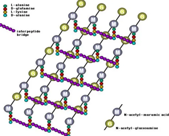
The cortex is composed of peptidoglycan with a structure similar to that of vegetative peptidoglycan with several spore specific modifications [10]. The germ cell wall lying under the cortex is also composed of peptidoglycan identical of the vegetative cell peptidoglycan [7]. The cortex is less cross linked than the vegetative cells [6]. Detailed structure of peptidoglycan of gram positive bacterial cell wall is shown in Figure 1.3.4 and Figure 1.3.5.
Formation of cortex is important for the reduction of water content and pH too which is essential for spore’s enzymatic dormancy maintenance [19].
Figure 1.3.4 Showing thicker Glycan Backbone, Inter-Peptide Bridges that Joins Amino Acid Side Chains (Gram Positive Cell Wall)
Figure 1.3.5 Two amino sugars
(N-acetyl- glucosamine =G N- acetylmuramic acid=M)
1. 4 amino acids
(L-alanine=L-ala, D-glutamic acid=D-glu, diaminopemelic acid=DAP, D-alanine =D-ala
1.3.3.3 Core
All of the genetic materials and enzymes are in the core, in a very concentrated form. For
dormancy or the resistance to environmental stresses, protection of the core is very important. A huge amount of DPA accumulates in the core which helps to reduce the water content and pH too. Water comprises 75% to 80% of the wet weight of the protoplast of a growing cell, whereas it makes up only 27% to 55% of the spore core wet weight depending of the species [19]. The spores of Bacillus subtilis mutants lacking DPA due to mutation in the operon spoVF that encodes DPA
synthetase [12]; have a lower core wet density and sensitive to wet heat and theses spores are
unstable and germinate spontaneously [12]. Stabilization and retention of dormancy by exogenous addition of DPA has also been reported. DPA is formed by a single oxidative reaction from as intermediate (dihydrodipiciolinic acid) in the biosynthetic pathway leading to the amino acid lysine. Biosynthesis of dipicolinic acid (pyridine-2, 6-dicarboxylic acid) is shown in Figure 1.3.6.
Theeonine, isoleucine Pyruvic Acid Dihydrodipicolinic acid Meso Diaminopimelic acid, Lysine Methionine Dipicolinic acid 2H Homoserein e Aspartic semialdehyde Aspartic Acid COO H COOH N COO H COOH N
Figure 1.3.6 Pathway of Biosynthesis of Dipicolinic Acid Showing its Relationship to the Pathway of Biosynthesis of the Amino Acids: threonine, isoleucine, methionine and lysine (Taken from the reference 6)
DPA is associated with wet heat resistance but it does not seem to play any role with dry heat resistance [12]. On germination, along with lots of other changes spore losses its cortex along with a huge leakage of DPA. Mineralization (accumulation of Ca2+) of the core is also helps with the reduction of water content. Ca2+ ions chelate with DPA and form a complex Ca-DPA (calcium dipicolanate).
In the core, there are small acid soluble proteins (SASPs) which are α, β, and γ bind with DNA and protect it from damaging agents like chemicals, heat, UV radiations, desiccation etc. type SASPs change the shape of DNA from B conformation to A conformation by saturating it [13]. When an endospore gets favorable conditions, losses its dormancy within minutes and germinates [14].
1.3.3.4 Formation of Spore Layers
Formation of spore layers is a very complex process and controlled by lots of genes. Adam Driks proposed a model for the synthesis of spore layers. According to that model [9] coat proteins are synthesized in cytoplasm and then layered on spore surface.
In Figure 1.3.6, MC shows mother cell l and FC shows the forespore. First SpolVA protein accumulates on the outer surface of the membrane from the mother cell. It also helps with the synthesis of peptidoglycan between the membranes. Above SpolVA protein, CoteE protein starts accumulating as shown in diagram (b) of Figure 1.3.6. There is a matrix between these two layers to glue them together (b). CotE directs the deposition of outer coat layers as show in diagram (c) of Figure 1.3.6. Inner coat forms as a layer underneath the CoatE shell as shown in (c) diagram of Figure 1.3.6 which is largely CotE independent. There are lots of other proteins of known and unknown functions play very important roles. For each and every step some genes are responsible which work in a very specific manner with a proper coordination with each other.
1.3.4 Conclusion
Bacterial spores are very different from the vegetative cells and lots of changes also take place during sporulation but still exact mechanisms of dormancy maintenance and the resistance to environmental stresses are not absolutely clear. Researchers have been trying to understand the mechanisms that take place in a bacterium or particularly in a spore so that techniques can be developed to inactivate them. Atmospheric pressure plasma can be used to sterilize different types of surfaces and equipment. It can also be used to remove dead cells or infectious proteins (prions). It is being used to perform lots of surgeries like cauterization and tissue de-vitalization [20], tissue desiccation [21], skin surgery [22], urology [14], gynecology, brain tumor surgery [23], gastroenterology [24], breast surgery [25], and bronchological endoscopy [26]. Atmospheric pressure cold plasma has immense physical and biological applications.
Figure 1.3.7 Model for Spore Coat Assembly; Upper diagram shows mother cell bearing spore before lysis. Lower diagram shows coat assembly of the boxed part in the above diagram. (Taken from the reference 9)
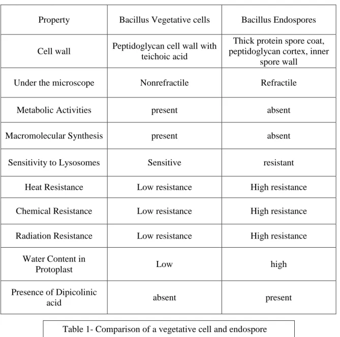
On the basis of above discussion a comparison between a bacillus vegetative and endospore is given below in table 1.
Property Bacillus Vegetative cells Bacillus Endospores
Cell wall Peptidoglycan cell wall with teichoic acid
Thick protein spore coat, peptidoglycan cortex, inner
spore wall Under the microscope Nonrefractile Refractile
Metabolic Activities present absent
Macromolecular Synthesis present absent
Sensitivity to Lysosomes Sensitive resistant
Heat Resistance Low resistance High resistance Chemical Resistance Low resistance High resistance Radiation Resistance Low resistance High resistance
Water Content in
Protoplast Low high
Presence of Dipicolinic
acid absent present
1.3.5 References
[1] Stragier P and Losick R. Molecular genetics of sporulation in Bacillus subtilis. Annu. Rev. Genet. 30:297–341, 1996.
[2] Vreeland RH, Rosenzweig WD, and Powers DW. Isolation of a 250 million-year-old halo-tolerant bacterium from a primary salt crystal. Nature 407:897–900, 2000.
[3] Driks A. Bacillus subtilis Spore Coat. American Society for Microbiology. p. 1–20 Vol. 63, No. 1.
[4] Losick R and Stragier P. Crisscross regulation of cell-type-specific gene expression during development in Bacillus subtilis. Nature 355:601–604, 1992.
[5] Lansing M. Prescott. “Microbiology”, 5th edition. The McGraw−Hill Companies, 2002.
[6] Stanier YR, Ingraham LJ, Wheelis LM, and Painter RP. The Microbial World. 5th edition. Prentice- Hall, Englewood Cliffs, New Jersey.
[7] Setlow P. Spores of Bacillus subtilis: their resistance to and killing by radiation, heat and chemicals. Journal of Applied Microbiology 101, 514–525, 2006.
[8] Nicholson WL, Munakata N, Horneck G, Melosh HJ, and Setlow P. Resistance of Bacillus endospores to extreme terrestrial and extra-terrestrial environments. Microbiology and Molecular Biology Review 64, 548–572, 2000.
[9] Driks A. Maximum shields: the assembly and function of the bacterial spore coat. TRENDS in Microbiology Vol.10 No.6, June 2002.
[10] Popham DL. Speciaized peptidoglycan of the bacterial endospore: the inner wall of lockbox. Cell Mol life Sci. 59:426-433, 2000.
[11] Murrel WG, and Warth AD. Composition and heat resistance of bacterial spores. In spores, vol 3 (Campbell LL and Halvorson HO, eds), pp. 1-24 American Society for Microbiology, Ann Arbor, Michigan, 1965.
[12] Paidhungat M, Setlow B, Driks A, and Setlow P. Characterization of spores of Bacillus subtilis which lack dipicolinic acid. J. Bacteriol. 182:5505-5512, 2000
[13] Setlow P. Mechanism for the prevention of Damage to DNA in Spores of Bacillus Species.Annu Rev Microbial 49:29 – 54, 1995.
[14] Paidhungat M, and Setlow P. Spore germination and outgrowth, p.537–548. In A. L. Sonenshein, J. Hoch, and R. Losick (ed.), Bacillus subtilis and its closest relatives. ASM Press, Washington, D.C., 2002.
[15] Bagyan I and Setlow P. Localization of the cortex lytic enzyme CwlJ in spores of Bacillus
subtilis. J. Bacteriol. 184, 1219–1224, 2002.
[16] Hullo MF. CotA of Bacillus subtilis is a copper-dependent laccase. J. Bacteriol. 183, 5426– 5430, 2001.
[17] Driks A. The Bacillus subtilis spore coat. Microbiol Mol Biol Rev 63, 1–20, 1999.
[18] Aronson AI, and Fitz-James P. Structure and morphogenesis of the bacterial spore coat. Bacteriol. Rev. 40:360–402, 1976.
[19] Gerhardt P. and Marquis RE. Spore thermoresistance mechanisms. In Regulation of Prokaryotic Development ed. Smith, I., Slepecky, R.A. and Setlow, P. pp. 43–63. Washington, DC: American Society for Microbiology, 1989.
[20] Raiser J and Zenker M. Argon plasma coagulation for open surgical and endoscopic applications: state of the art. J. Phys. D Appl. Phys. 39, 3520.70, 2006.
[21] Pollack S, Carruthers A, and Grekin RC. The History of Electrosurgery. Dermatol. Surg., 26, 904-908, 2000.
[22] Brand CU, Blum A, Schlegel A, Farin G, and Garbe C. Application of argon plasma coagulation in skin surgery. Dermatology 197152–7, 1998.
[23] Tirakotai W, Mennel HD, Celik I, Kolodziej M, Bertalanffy H, and Riegel T. Argon plasma coagulation (APC) in brain tumor surgery: experimental study and clinical experiences. Clini. Neuropathol. 23, 257–61, 2004.
[24] Ginsberg GG, Barkun AN, Bosco JJ, Burdick JS, Isenberg G A, Nakao NL, Petersen BT, Silverman WB, Slivka A, and Kelsey PB. The argon plasma coagulator. Gastrointestinal Endoscopy, Volume 55, No.7, 2002.
[25] Ridings P, Bucknall TE, and Bailey C. Argon Beam coagulation asan adjunct in breast-conserving surgery. Ann. R. Coll. Surg. Engl. 80, 61–2, 1998.
[26] Reichle G, Freitag L, Kullmann HJ, Prenzel R, Macha HN, and Farin G. Argon Plasma Coagulation (APC) in bronchology: A new method –alternative or complementary?. J. Bronchol. 7, 109–17, 2000.
Chapter 2
Electrical and Optical Characterization of Cold Atmospheric
Pressure Plasma Torch (CAPPLAT – 9Ne) the Commercial
unit and the Effects of N
2gas on Argon Plasma Jet
2.1 Introduction
Normally, to produce non-equilibrium plasma, low pressure (about 10-4 to 10-2 kPa) is required. Maintenance of low pressure or vacuum, limits its use to batch processes besides that the size of the substrate and cost effectiveness are the main hurdles in the successful commercial use of non-equilibrium cold atmospheric plasmas. To overcome these problems, several novel atmospheric pressure plasma generating sources have been developed like arc discharges, plasma torches, barrier discharges, corona discharges, plasma jets and micro-plasma.
All over the world, people have been using plasma for a long time but the invention of non-equilibrium, atmospheric plasmas heralded a new era of their applications in different fields. Non-equilibrium plasmas like one atmosphere uniform glow discharge plasma (OAUGDP), atmospheric pressure plasma jet (APPJ), micro-beam plasma generator, plasma needle, plasma torches, plasma bullet etc. are often used for ozone generation, surface treatment [1-3], pollution control, radiation sources etc.. Bio-plasma is also a very fast emerging field of plasma applications. Efforts are being made to achieve specific parameters to kill different types of harmful microorganisms or diseased cells to treat some dreadful diseases. Actually, we also tried to characterize our handmade torch for its bio-application (sterilization).
At atmospheric pressure, a low temperature (22 to 35°C) , non-equilibrium plasma discharge generating device (CAPPLAT) fed by a high-voltage pulsed power source had already been
developed and used successfully for both chemical vapor deposition (CVD) and polymer surface treatment [5, 8-11]. That device had also been commercialized under the name of “CAPPLAT” by Cresur Corporation [6]. The CAPPLAT - 9 Ne, we used to conduct the experiments had a little bit different configuration from the basic CAPPLAT unit. The CAPPLAT - 9 Ne worked at higher sinusoidal feeding voltage (Vpp 20 kV) than the basic CAPPLAT unit manufactured by Cresur
Corporation. To generate plasma discharge, Ar gas was used as a working gas or a primary gas, N2
gas was mixed to achieve a homogeneous discharge. Electrical and optical properties of the homogeneous plasma discharge were characterized using a high voltage probe, current probe and optical emission spectroscopy. Finally, in order to investigate the effect of the stabilized plasma discharge on the viability of Bacillus subtilis endospores, the endospores (1.0 X 10⁷ to 4.0 X 10⁷ spores/ml) were exposed to the plasma for different durations. We could successfully inactivate a
Bacillus endospore population of 1.0 X 10⁷ to 4.0 X 10⁷ endospores/ml. The experimental details about bacterial endospores are discussed in Chapter 4
2.2 Experimental Setup and Methods
2.2.1 Plasma Device
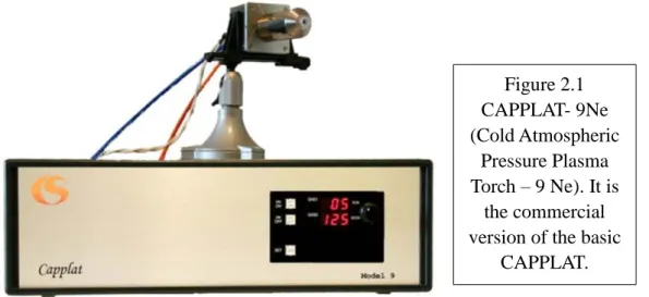
We used CAPPLAT-9 Ne (Figure 2.1) and a hand-made plasma torch (Figure 2.4) to generate non-equilibrium plasma at atmospheric pressure.
Figure 2.1 CAPPLAT- 9Ne (Cold Atmospheric Pressure Plasma Torch – 9 Ne). It is the commercial version of the basic
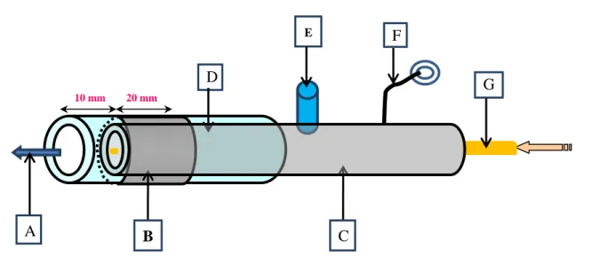
This device was based on the principle of dielectric barrier surface discharge. The schematic illustration of plasma torch is given in Figure 2.2. It comprised of two coaxial electrodes with a layer of dielectric barrier between them. The schematic illustration of electrode arrangements is given in Figure 2.3. The inner electrode was a copper tube with the outer diameter of 8 mm and the inner diameter of 7 mm. The inner electrode was connected to high sinusoidal voltage (Vpp 20 kV)
at a frequency of 20 kHz. The outer electrode was a piece of copper foil of 20 mm width. The outer electrode was grounded. A silicone tube (Laboran® silicone tube) of thickness of 2 mm was sandwiched between two electrodes as a dielectric barrier. Arrangement of electrodes and dielectric barrier is illustrated in Figure 2.4. An inlet tube was also inserted into the copper tube to feed Ar gas (working gas) and N2 gas (additive gas) into the hollow inner electrode. A glass capillary tube was
inserted into the hollow inner electrode for the direct injection of other additive gases like O2 or for
the addition of H2O2 through bubbling with the argon gas as a carrier gas, to the plasma discharge.
Our handmade plasma is shown in Figure 2.4.
Figure 2.2 Schematic illustration of plasma torch; A: Plasma jet; B: grounded outer electrode; C: Inner copper electrode; D: Dielectric substance (silicon tube); E: Inlet for the mixture of Ar and N2; F: Wire connecting inner copper electrode to a high voltage source; G: Glass capillary
for other additive gases like O2 or for the addition of other substances via bubbling.
10 mm 20 mm D E G B A C F
For plasma jet generation, 10 slm (standard liter per minute) of Ar gas as a working gas and the different volumes of N2 gas (100 to 200 sccm (standard cubic centimeter per minute)) as an
additive gas were used. All of the volumes were controlled by mass flow controllers installed in the CAPPLAT – 9Ne. Before feeding the mixture of gases into the hollow inner electrode, they were passed through a mixing device to have a uniform effect (quenching) of nitrogen gas on argon gas. N2 could be added through the glass capillary inserted into the hollow inner electrode for the direct
injection into the plasma discharge but it was not effective. There was no quenching effect of N2 [5]
G D C
B
Figure 2.3 Schematic illustration of the Arrangement of electrodes and dielectric barrier C: inner high voltage electrode; G: glass capillary for direct gas injection into the plasma jet; D: dielectric substance (silicone tube); B: outer grounded electrode.
(The alphabets showing different parts, are the same as in Figure 2.2)
and the plasma discharge was as filamentary as it was before N2 addition. To have quenching effect
we need to add gases to direct plasma not to remote plasma (after-glow discharge).
When O2 gas or H2O2 with Ar gas as a carrier gas were added through the capillary, there were
Figure 2.5 Schematic illustration for experimental setup and the setup for OES and electric
measurements. 1: Ar gas (working gas); 2: N2 gas (additive gas) ; 3: Gas mixing device; 4:
Plasma torch; 5: A.C source; 6: CAPPLAT; 7 & 8: Mass flow controllers; 9: stage; 10: Substrate; 11: Plasma jet; 12: optical fiber ; 13: Optical emission spectroscopy; 14: Personal computer; 15: Oscilloscope; 16: Current probe; 17. Voltage probe; 18: Inlet for the mixture of Ar&N2; 19: Inner electrode; 20: Outer electrode; 21: capillary to inject other gases
into the plasma jet directly
no effects on the appearance of the jet and consequently optical emission spectrum and the waveforms of current and voltage were also almost unaltered but the effects of the jet on the substrate were drastic. When O2 was added to the mixture of Ar and N2 it caused such a massive
quenching that we couldn’t get any plasma discharge so we added it to the plasma discharge directly (direct injection mode) through the capillary. Schematic illustration of the whole experimental set up is given in Figure 2.5 whereas to show the addition of Ar and N2 is shown in
Figure 2.8.
2.2.2 Electrical Measurements
The high sinusoidal voltage (Vpp 20 kV), applied to achieve the plasma discharge, was measured
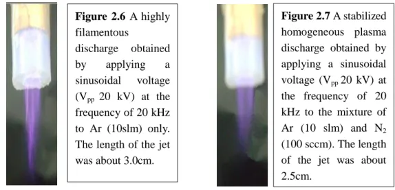
using a 1000:1 high-voltage probe (Tektronix P6015A). The voltage probe was attached to the inner electrode of the plasma torch. The capacitive current was monitored using a wide band current monitor (PearsonTM current monitor) manufactured by Pearson Electronics Inc., Palo Alto, California, U.S.A.. The cable connected to the outer electrode was passed through the wide band current monitor. A digital phosphor oscilloscope (Tektronix TDS3012C) was inserted into the circuit to record the waveforms of voltage and current. The setup for electrical measurements is shown in Figure 2.5. Electrical measurements were recorded for filamentary plasma discharge (see Figure 2.6) when only Ar gas was being used and for stabilized plasma discharge (see Figure 2.7) when both Ar gas and N2 gas were used to get a stabilized plasma discharge. Figure 2.8 has the
schematic illustration of Ar-N2 addition to the plasma discharge. The electrical wave forms are
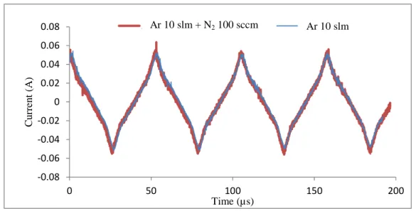
given in Figure 2.9 and Figure 2.10. To see the effect of the gas composition on total current, the current probe was attached to the outer electrode to check the total current in both cases; Ar discharge and Ar-N2 discharge and the waveforms are shown in Figure 2.11.
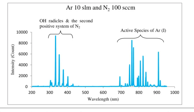
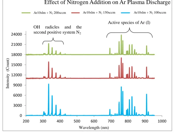
The optical emission spectra of plasmas were collected using Multiband Plasma–process Monitor (MPM, Hamamatsu Photonics C7460). The spectral range was 200 nm to 950 nm with the wavelength resolution of < 2nm FWHM (full width at half-maximum). The optical fiber probe was kept 0.5 cm below and 1.5 cm away from the mouth of the plasma torch to capture the spectra of plasma emission. Monitoring and acquisition of data was carried out by a personal computer, connected to the multiband plasma-process monitor. The optical spectrum for Ar-plasma discharge is given in Figure 2.12. The spectrum for Ar-N2 plasma discharge is shown in Figure 2.13. The
comparison of spectra for different plasma discharges are given in Figure 2.14.
2.3 Results and Discussion
2.3.1 Electrical Characterization of Ar Plasma Jet and the Effects of the Additive gas (N2)
Since Kanazawa et al. [7] generated homogeneous atmospheric plasma with He gas using dielectric barrier, lots of work about non-equilibrium homogeneous dielectric barrier discharge at atmospheric pressure has been done. Our hand-made torch is based on the principal of dielectric barrier surface discharge at atmospheric pressure. A high sinusoidal voltage (Vpp 20 kV, frequency
20 kHz) was used to generate the plasma discharge. Ar as a primary gas (working gas) generated highly filamentous plasma shown in Figure 2.6. Dielectric barrier substances are often used to achieve homogeneous discharges. The insulating nature of dielectric substance restricts the movement of the charge and subsequently there is a charge accumulation on the surface of dielectric barrier. In the other half cycle when the polarity of driving oscillation changes, the accumulated charge is expelled from the dielectric barrier surface to the other electrode. When the accumulation of charge exceeds its breakdown, micro-discharges (filaments) occur. In spite of the use of dielectric barrier, Ar gas plasma discharge was extremely filamentous as shown in Figure 2.6.
stabilized plasma discharge shown in Figure 2.7. N2 gas stabilized the plasma discharge by the
process of quenching. With the addition of N2, jet got stabilized but shorter in length and less
intense.
Arrangement to feed gases into the plasma torch to get the plasma discharge is shown in Figure 2.8.
The waveforms of time dependent current and applied voltage are shown in Figure 2.9 and Figure 2.10. To see the impact of micro-discharges on the current instead of average waveform,
Figure 2.6 A highly filamentous discharge obtained by applying a sinusoidal voltage (Vpp 20 kV) at the frequency of 20 kHz to Ar (10slm) only. The length of the jet was about 3.0cm. Figure 2.7 A stabilized homogeneous plasma discharge obtained by applying a sinusoidal voltage (Vpp 20 kV) at the frequency of 20 kHz to the mixture of Ar (10 slm) and N2 (100 sccm). The length of the jet was about 2.5cm. 2 3 4 Ar N2 1 6 5
Figure 2.8 1: Capillary; 2: Inner electrode; 3: Dielectric barrier; 4: Outer electrode; 5: Plasma Jet; 6: Inlet for the mixture of gases (Ar and N2)