Q series Motion Controller
for the iQ Platform
Extract more performance with the multiple
CPU system-based controller platform.
A new platform
aimed at improving total
system performance!
Multiple CPU High Speed Bus
-Equipped with a Multiple CPU high speed bus reserved specifically for
CPU-to-CPU communication.
With this reserved Multiple CPU high speed bus, data transfer of 0.88ms
period is possible for up to 14k words.
-The Multiple CPU high speed transmission cycle is synchronized with the
motion control cycle thus optimizing the control system.
High speed and high accuracy due to
improvements in motion control performance
-2 times (0.44ms/6 axes) the motion operation
performance as before resulting in shorter system
tact times.
-Instruction communication to the servo amplifier can
be executed in as little as a 0.44ms period, realizing
high-accuracy synchronous control and
speed/position control.
-A motion control specific processor (high
performance 64bitRISC) and a proprietary
acceleration algorithm ASIC improve hardware
efficiency.
-Using the MELSEC Q series universal model CPU,
sequence processing is also accelerated.
(Using the Q06UDHCPU, the PLC basic instruction
time is 9.5ns.)
-Equipped with various motion control functions such
SSCNET3Multiple CPU High Speed Bus
Q series PLC system bus
PLC I/O Module PLC Intelligent Function Module
Motion CPU PLC CPU
Motion Module
Servo
Amplifier
Universal Model PLC Control
Processor
Multiple CPU High Speed Transmission Area
Multiple CPU High Speed Transmission Area Device Memory Device Memory
Motion Control Processor
Being Introduced to the Motion controller Q series is the iQ Platform-based
Q173DCPU/Q172DCPU.
Motion control performance has been drastically improved.
2
Need-based System Construction
-Up to 4 CPU modules can be freely selected in the
Multiple CPU system. (1 PLC CPU required)
-Control up to 96 axes per system using multiple Motion
CPUs. (Three Q173DCPU modules use).
-An optimum decentralized control system can be
constructed using Multiple CPUs.
Control is optimized by dispersing processing across the
Multiple CPUs with the PLC CPU handling general
machine control and the Motion CPU handling servo
control tasks.
System expandability is accomplished with ease due to
the availability of over 100 different types of MELSEC Q
series modules.
-SSCNET
3
based MR-J3 servo amplifiers deliver a high
speed, high accuracy solution.
SSCNET (Servo System Controller NETwork)
A new advanced Engineering Environment
MELSOFT MT Works2
-Easier operation allows for both programming and debugging time to
be substantially reduced.
-User-create, easily understood device labels can now be created,
simplifying appropriation within the program.
-New import/export function for cam data in CSV file format.
-Substantial shortening of communication time when reading and
writing to the Motion CPU. (Q173DCPU/Q172DCPU use)
Higher performance motion control!
Motion Processing Acceleration
PLC program interrupt for
Multiple CPUs synchronization
■
Approximately double the basic motion performance
and 1/4 the Motion SFC processing time.
Multiple CPU High Speed Bus
■
With reserved Multiple CPU high speed bus, data transfer of 0.88ms period is possible for up to 14k words.
■
Using the new PLC interrupt function synchronized
with the motion operation cycle (0.88ms),
it is possible to achieve real time processing
of the ladder program.
Q173DCPU
Performance
Basic motion performance
(With 0.44 ms operation cycle time) In case of SV13
Multiple CPU high speed data transfer
The Multiple high speed
transmission cycle is the same as
the Motion Control cycle time.
Increased controllability
Motion SFC processing time
Process time for D800L=D802L + D804L 3 axes
6 axes
Approx. 2 times
the performance
Q173HCPU
Shared memory capacity
Q173DCPU
Processing time
2.34ms
11.75ms
Reduced to
approx. 1/4
Q173HCPU
Q06UDHCPU + Q173DCPU
Capacity
4k word
14k word
3.5 times increase
(Up to14k words)
Q06HCPU + Q173HCPU
Q06UDHCPU
In-position response time
Program example
Q06HCPU
Acceleration of in-position signal response time
D(P).SVST In-position signal Servo program start
dedicated instruction [K0 : Real] 1 INC-1
Axis 1, 200 PLS Speed 10000 PLS/sec
1) A motor real time value can be compared against a
specific point and if this point is overrun, the PLC can
turn on an output signal.
(Variation of comparison processing does not have an
influence on the scan time of the ladder which is
processed within 0.88ms.)
2) Multiple Motion CPUs can be started simultaneously.
4
■
Automatic refresh setting count has increased from 4 to 32.
<In-position response time>
In a 2 CPUs, Multiple CPU system consisting of a PLC CPU and Motion CPU, the Motion CPU receives the in-position signal from the servo amplifier of the first axis. Next, the PLC CPU sends a start command to the second amplifier. This example thus shows the time it takes from the stopping of motion on one axis until the beginning of motion on a second axis. Since the Motion CPU and PLC CPU must continuously communicate back-and-forth, this time is a good indicator of CPU-to-CPU data transfer speed and more importantly, overall system performance and tact time.
-More freedom in setting up the program for CPU-to-CPU data exchange.
-Motion critical data such as position and velocity information can be assigned to specific CPU-to-CPU high-speed refresh area thus synchronizing their exchange between the Multiple CPU’s with that of the motion control system’s operation cycle.
+ Q173DCPU
Processing time
Measurement details
Decreased
in 1/2
+ Q173HCPU
In-position response time In-position
signal
Time Motor
speed
Motion Dedicated PLC Instruction
Large reduction in programming
read/write time
■
Introducing easy-to-use Motion dedicated PLC
instructions.
■
Increased debugging efficiency by reducing
program read/write time to 1/3 the previous
execution time.
Issue multiple instructions at the same time
Ex: Execution of 3 Motion dedicated SVST instruction at the same time.
Indirectly set data and execute instructions at the same time
Ex: Indirect data setting of speed and position plus execution of the Motion dedicated SVST instruction all at the same time.
Ladder program DMOV DMOV DP.SVST M0
D P. S V S T H 3 E 1 " J 1 " K 0 D P. S V S T H 3 E 1 " J 2 " K 1 D P. S V S T H 3 E 1 " J 3 " K 2 R S T M 0 M0
[K0 : Real] 1 INC-1
Axis 1, U3E0¥G12046 PLS Speed U3E0¥G12048 PLS/sec
Ladder program
Servo program
Motion CPU communication time
Servo program read time
Q173DCPU
Communication time
Approx. 3 times
faster
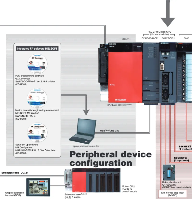
Q173HCPU U3E0¥ G12046 U3E0¥ G12048 K10000 K500System Configuration
USB(Note9)/RS-232
SSCNET3 (2 systems)
SSCNET3 (1 system)
Graphic operation (Note10)
Motion CPU/ PLC CPU control module
■
Compatible with the Q Series PLC (Platform) in the Multiple CPU system.
■
The appropriate CPU modules for PLC control and Motion control can be selected to meet the application requirements.
■
The Multiple CPU configuration allows up to 4 CPU modules to be selected. (1 PLC CPU must be used.)
■
Up to 96 axes of servomotors per system can be controlled by using 3 modules of Q173DCPU.
Extension cable QC䊐B
CPU base Q3䊐DB(Note6)
EMI Forced stop input
Peripheral device
configuration
Battery holder unit Q170DBATC
(Q6BAT has been installed) PLC CPU/Motion CPU
(Up to 4 modules)
Q6䊐P Q䊐UD(E)(H)CPU Q17䊐DCPU QI60
Laptop personal computer
Flexible High-Speed Motion Control System Achieved with Multiple
PLC programming software GX Developer
SW8D5C-GPPW-E Ver.8.48A or later (CD-ROM)
Motion controller engineering environment MELSOFT MT Works2
SW1DNC-MTW2-E (CD-ROM)
Servo set up software MR Configurator
MRZJW3-SETUP221E Ver.C0 or later (CD-ROM)
Manual pulse generator (3 units per module) MR-HDP01
Serial absolute synchronous encoder (2 units per module)
Q170ENC
Motion CPU input/output (Up to 256 points)
External interrupt input (16 points)
Servo external signal (Note12)
(FLS,RLS,STOP,DOG/CHANGE)✕8 axes/module
Servo external signal(Note12)
(FLS, RLS, DOG)
Device
configuration
Notes :1. Only input module among Motion CPU control modules can be accessed from PLC CPU.
2. Motion modules (Q172DLX/Q172DEX/Q173DPX) cannot be installed in CPU slot and I/O slot 0 to 2 of the main base unit.
3. Motion modules (Q172LX/Q172EX(-S2)/Q173PX) for Q17䊐HCPU/Q17䊐CPUN
cannot be used.
4. Installation position of Q172DEX is only the main base unit. It cannot be used on the extension base unit.
5. Other CPU modules cannot be accessed from Motion CPU.
6. It is impossible to mount the main base unit by DIN rail when using the Motion CPU module.
7. Be sure to use the cable for forced stop input (sold separately). The forced stop cannot be released without using it.
8. Be sure to use the external battery.
9. USB cannot be used in WindowsNT® 4.0.
10. Motion CPU cannot control the module installed to the QA1S6䊐B.
11. The servo amplifiers for Linear servomotors are required.
12. Connecting target can be selected for each axis from general-purpose input of servo amplifier or Q172DLX.
Motion CPU control(Note1, 2, 3)
modules
PLC CPU control (Note5)
modules
QX/Y䊐䊐 Q172DLX Q172DEX(Note4) Q173DPX
Servo amplifier MR-J3-䊐B
Servomotor
Servomotor
Servo amplifier MR-J3-䊐B
Q173DCPU : 2 systems(Up to 32 axes) Q172DCPU : 1 system(Up to 8 axes)
Linear servomotor(Note11)
Motion SFC compatible
Conveyor assembly useOperating system software packages
Dedicated language
Motion SFC compatible
Automatic machinery useMechanical support language
Operating system software
SW8DNC-SV䊐䊐Q䊐
(CD-ROM)
Electronic component assembly, Inserter, Feeder, Molder, Conveying equipment, Paint applicator, Chip mounting, Wafer slicer, Loader/Unloader, Bonding machine, X-Y table
Linear interpolation (1 to 4 axes), Circular interpolation, Constant-speed, Fixed-pitch feed, Speed control with fixed position stop, Speed switching, Speed control, Speed/position switching
Press feeder, Food processing, Food packaging, Winding machine, Spinning machine, Textile machine, Printing machine, Book binder, Tire molder, Paper-making machine