sustainability
Article
Development and Evaluation of Applicable Optimal
Terminal Box Control Algorithms for Energy
Management Control Systems
Yoon-Bok Seong1and Young-Hum Cho2,*
1 Senior Research Engineer, Construction & Energy Business Division, Korea Conformity Laboratories, 199, Gasandigital 1-ro, Geumcheon-gu, Seoul 08503, Korea; [email protected]
2 School of Architecture, Yeungnam University, 280 Daehak-Ro, Gyeongsan, Gyeongbuk 38541, Korea * Correspondence: [email protected]; Tel./Fax: +82-53-810-3081
Academic Editor: Marc A. Rosen
Received: 16 August 2016; Accepted: 25 October 2016; Published: 9 November 2016
Abstract:Common energy management control systems (EMCS) in building HVAC systems could
be made much more energy efficient without sacrificing comfort. Most researchers have focused on implementing optimal control algorithms in Variable Air Volume (VAV) systems with EMC functions. Previous studies have paid little attention to using terminal box EMC functions integrated with main AHU (Air Handling Unit) systems. Terminal boxes with EMCS may cause occupant discomfort and waste excessive energy if they do not have the proper operation control functions. The objective of this study is to evaluate the impact of energy consumption and estimate building energy savings on the optimal minimum air flow of single duct VAV terminal boxes and develop applicable optimal terminal box control algorithms for EMCS. This paper presents a dynamic model of a VAV terminal box with hydronic reheat, develops optimal terminal box control algorithms and applies the developed EMCS algorithms to an actual building. The results of this study show that optimal terminal box control algorithms can stably maintain the set room air temperature and reduce energy consumption for varying heating loads compared to conventional control algorithms.
Keywords:VAV terminal box; control algorithms; energy savings; thermal comfort
1. Introduction
HVAC systems consume more than 30% of building energy. Methods of saving building HVAC energy include installation or replacement of the HVAC system and upgrading the energy management control system (EMCS). Even with improved HVAC equipment, a building cannot achieve energy savings if the system has an unsuitable operation control system. Considerable energy savings can be attained by properly operating the HVAC system. A typical EMCS in a building HVAC system could be made much more energy efficient without sacrificing comfort.
Most researchers have focused on implementing optimal control algorithms in VAV systems with EMC functions. Elovitz et al. [1] and Krakow et al. [2] discussed the minimum outside air control method and economizer for VAV systems. Optimal supply air temperature control in VAV systems was suggested by Ke et al. [3]. Zaheer-uddin [4] suggested optimal operating strategies. Engdahl and Johansson [5] investigated the energy savings potential of a controlled supply air temperature of a VAV based system by a comparison with a constant supply air temperature. Wei [6] examined the major factors that impact the supply air temperature reset schedule which minimizes the overall heating energy, cooling energy and fan power consumption. Nassif and Moujaes [7] proposed a new damper control strategy for the outdoor, discharge and recirculation air dampers of the economizer in a VAV system. Taylor et al. [8] discussed the minimum air flow set point of the terminal units. Cho and Liu
identified the relationship between the supply air temperature and minimum air flow rate [9] and the correlation between the minimum air flow and discharge air temperature that will maintain room thermal comfort using a CFD simulation [10]. Kang et al. [11] determined the relationship between supply temperature, air flow rate and energy by height and presented a terminal unit air flow rate control method considering stratification and IAQ. Kim et al. [12] presented a method for controlling the supply temperature and air flow rate of a terminal unit to control stratification. Taylor et al. [13] conduct an energy study on systems that use the conventional box and dual maximum box control methods. Zhang et al. [14] investigated how the VAV terminal box minimum air flow setting influences system energy use as well as building IAQ. However, previous studies have paid little attention to using terminal box EMC functions that are integrated with the main AHU system.
Terminal boxes are one of the major building HVAC components and directly impact building room comfort and energy costs. The minimum air flow of terminal boxes is a key factor for comfort, indoor air quality (IAQ) and energy cost. Current terminal boxes with EMCS may cause occupant discomfort and waste energy because they have inappropriate operation control functions of minimum air flow. Existing terminal boxes in EMC algorithms use mostly empirical methods by using a fixed minimum air flow. This control sequence can cause occupant discomfort or use excessive energy. In addition, advanced optimization and control techniques are too complex between maximum and minimum air flow set point and hard to implement on existing commercially EMCS. Therefore, the optimized control strategy and operation schedules of the terminal boxes with proper minimum air flow should be studied to improve indoor air quality, thermal comfort and energy savings.
The objective of this study is to evaluate the impact of energy consumption and estimate building energy savings on the optimal minimum air flow of single duct VAV terminal boxes and develop applicable optimal terminal box control algorithms for EMCS. This paper presents a dynamic model of a VAV terminal box with hydronic reheat, develops optimal terminal box control algorithms and evaluates the developed EMCS algorithms to an actual building. The terminal box energy consumption and thermal comfort are compared between conventional and improved control using measured data.
2. VAV Terminal Box Modeling
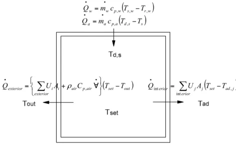
The single-duct pressure independent VAV terminal box with hydronic reheat system consists of a modulation damper and temperature sensor and a reheat coil installed in the discharge for spaces requiring heating. Figure1presents the schematic diagram of the single-duct pressure independent VAV terminal box with hydronic reheat.
To analysis energy consumption by terminal box, zone load of simple zone sensible load modeling should be calculated as shown in Equation (1); discharge temperature and pressure of reheating coil modeling should be calculated as shown in Equations (2)–(11); and flow rate of damper and valve modeling should be calculated as shown in Equations (12)–(16).
2.1. Zone Model
Sustainability2016,8, 1151 3 of 22
Figure 1. Schematic diagram of a single-duct pressure independent VAV terminal box with hydronic
Figure 1. Schematic diagram of a single-duct pressure independent VAV terminal box with hydronic reheat.
Figure 2. The terms in a zone load calculation.
set adj
erior j j
erior U A T T
Q ,
int
int
set out
air p air exterior i i
exterior UA C T T
Q
,
sw rw
w p w
w m c T T
Q , , ,
ds s
a p a
a m c T T
Q , ,
Figure 2.The terms in a zone load calculation.
The fully mixed air mass temperature is given by Equation (1).
d·TR dt =
1
ρ·V·Ca (
qi+
∑
exterior
UiAi+mv• ·Ca !
·(Tr−Tout) +
∑
interior
UjAjTr−Tad,j )
(1)
2.2. Reheating Coil Model
a function of NTU (number of transfer units) for a typical cross flow heat exchanger with both fluids unmixed type. Total heat transfer rate, water and air side heat flux can be calculated by Equations (2)–(4). When the room can maintain a constant temperature, total heat transfer, the air and water side heat flux have a heat balance as in Equation (5).
•
Qtotal =ε·Cmin(Ts,w−Ts) (2)
•
Qw=Cw(Ts,w−Tr,w) (3)
•
Qa=Ca(Td,s−Ts) (4)
•
Qa =
•
Qw =
•
Qtotal (5)
The steady state air and water outlet temperature are found using the definition of heat exchanger effectiveness by Equations (6) and (7).
Td,s =Ts+ε·Cmin
Ca ·(Ts,w−Ts) (6)
Tr,w =Ts,w− Ca
Cw ·(Td,s−Ts) (7)
Air and water dynamic outlet temperature are calculated using coil time constant by Equations (8) and (9).
dTD,d,s
dt =
Td,s−TD,d,s tcoil
(8)
dTD,r,w
dt =
Tr,w−TD,r,w tcoil
(9)
Air and water inlet pressure are calculated from the outlet pressure and flow rates by Equations (10) and (11).
Pa,i =Pa,o+ka·ma2 (10)
Pw,i =Pw,o+kw·mw2 (11)
2.3. Damper and Valve Model
A damper or valve is essentially a variable fluid resistance. The method in which the flow rate varies with damper or valve position is known as the damper or valve characteristic. The model calculated the inlet pressure as a function of mass flow rate and relative damper or valve position. The pressure loss coefficient for steady-state is derived as Equations (12) and (13). These equations can be related to volume flow rate entering the terminal box as in the following Equations (14) and (15). The flow rate related to air flow resistance can be calculated by Equation (16).
∆Pbox=kbox·Pv (12)
∆Pbox=kbox·ρ·v
2
2 (13)
∆Pbox =kbox· ρ·mb
2
2·Ab2
(14)
∆Pbox=Sbox·m2 (15)
•
m=
s
∆Pbox
Sbox
Sustainability2016,8, 1151 5 of 22
3. Optimal Minimum Air Flow
3.1. Minimum Air Flow Based on Heating Load
The minimum air flow for a heating load is the air flow required by the room design heating load. The minimum air flow needed to satisfy the building heating load requirement can be calculated with Equation (17):
•
Vmin,h=
Qh ρ·Cp·(Td,s−Tr)
(17)
where •
Vmin,h—air volumetric flow rate for heating load, ft3/min Qh—Room heating load, Btu/hr
Tr—Room air temperature,◦F
Td,s—Discharge air temperature,◦F
ρ—standard air density, lbm/ft3 Cp—specific heat of air, Btu/lbm◦F
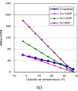
In order to calculate the required air flow for the heating load, the discharge air temperature should first be determined. This temperature can be calculated based on Cho and Liu’s [10] determined optimal discharge air temperature. It is used to find the proper room air temperature distribution and minimum rate of energy usage. Figure3compares the optimal air flow and air flows using differing fixed discharge air temperatures at various occupied conditions. The required air flow in unoccupied conditions was higher than that in occupied conditions because of a high room heating load requirement. During the high room heating load condition (at the low outside air temperature condition), the discharge air temperature is higher than 90◦F based on the calculated optimal value. However, the discharge air temperature is lower than 90◦F during the low room heating load condition. Therefore, the discharge air temperature cannot be fixed at a specific temperature; instead, it varies according to the room heating load and air flow.
,
= ∙ ∙
,
−
,
,
ρ
(
a
) (
b
)
0 40 80 120 160 200 240
-10 0 10 20 30 40
Outside air temperature (F)
Ai
rf
lo
w
(C
F
M
)
T=optimal
Ts=120F Ts=100F
Ts=90F
0 40 80 120 160 200 240
-10 0 10 20 30 40
Outside air temperature (F)
A
irf
lo
w
(C
F
M
)
T=optimal
Ts=120F
Ts=100F
Ts=90F
(
c
)
Comparison of the calculated air flow with different discharge ai
−
–
–
0 40 80 120 160 200 240
-10 0 10 20 30 40
Outside air temperature (F)
Ai
rf
lo
w
(
C
F
M
)
T=optimal Ts=120F Ts=100F Ts=90F
Figure 3. Comparison of the calculated air flow with different discharge air temperature for different occupied conditions: (a) unoccupied condition; (b) 50% occupied condition; and (c) fully occupied condition.
Figure4compares the reheating energy consumption of the optimal discharge air temperature and the fixed 90◦F discharge air temperature. The optimal discharge air temperature reduces energy consumption by 33% to 35%. During unoccupied conditions, even more reheating energy can be saved.
Figure 4. Comparison of the reheating energy consumption between fixed supply air temperature
−
– –
0 5,000 10,000 15,000 20,000 25,000 30,000 35,000 40,000 45,000
Unoccupied condition 50% occupied condition Fully occupied condition
E
n
e
rg
y
c
o
n
s
u
m
p
ti
o
n
(B
T
U
)
Supply air temp. = 90 F
Optimal supply air temp.
Figure 4.Comparison of the reheating energy consumption between fixed supply air temperature and optimal supply air temperature.
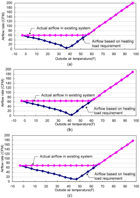
Figure5compares the minimum air flow rates of the actual air flow in an existing system with the potentially improved (simulated). These are based on the heating load requirement under differing occupied conditions. The discharge air temperature used the calculated optimal value.
Sustainability2016,8, 1151 7 of 22
(a)
(b)
(c)
Figure 5. Comparison of air flow between actual air flow in existing system and calculated air f
–
=
−
−
, min
, 1
0 20 40 60 80 100 120 140 160 180 200
-10 0 10 20 30 40 50 60 70 80 90 100 Outside air temperature(F)
A
ir
flo
w
ra
te
(C
F
M
)
0 20 40 60 80 100 120 140 160 180 200
-10 0 10 20 30 40 50 60 70 80 90 100 Outside air temperature(F)
A
irf
lo
w
ra
te
(C
F
M
)
0 20 40 60 80 100 120 140 160 180 200
-10 0 10 20 30 40 50 60 70 80 90 100 Outside air temperature(F)
A
irf
lo
w
ra
te
(C
F
M
)
Figure 5.Comparison of air flow between actual air flow in existing system and calculated air flow based on heating load requirement for different occupied conditions: (a) fully occupied condition; (b) 50% occupied condition; and (c) unoccupied condition.
3.2. Minimum Air Flow Based on Ventilation Requirement
The minimum rate of air flow that satisfies the ventilation requirements can be calculated using Equations (18)–(20).
αoa= Min(Max( TR−Ts TR−TOA
, minoa), 1) (18)
where
αoa—AHU outside air intake ratio, % TR—Return air temperature,◦F TOA—Outside air temperature,◦F TS—Supply air temperature,◦F
•
where •
Vf—air volumetric flow rate for fresh air requirement, ft3/min
•
Vmin,v—air volumetric flow rate for ventilation, ft3/min
Rp—outdoor air flow rate required per person as determined from ASHRAE Standard 62, 2004 Pz—zone population, person
Ra—outdoor air flow rate required per unit area as determined from ASHRAE Standard 62, 2004 Az—zone floor area, ft2
•
Vmin,v= •
Vf
αoa (20)
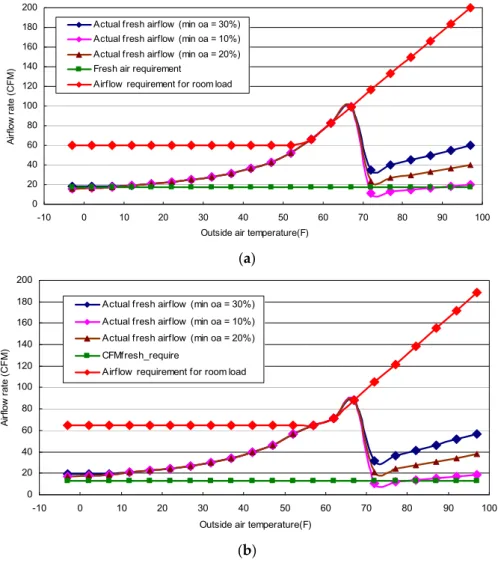
Figure6compares the air flow between the actual fresh air flow with different minimum outside air intake ratios and fresh air requirements at different occupied conditions. During the occupied and 10% minimum outside air intake conditions, the actual fresh air flow was lower than the required minimum air flow. This may cause an IAQ issue.
,
,
=
(a)
(b)
0 20 40 60 80 100 120 140 160 180 200
-10 0 10 20 30 40 50 60 70 80 90 100
Outside air temperature(F)
A
irf
lo
w
ra
te
(C
F
M
)
Actual fresh airflow (min oa = 30%) Actual fresh airflow (min oa = 10%) Actual fresh airflow (min oa = 20%) Fresh air requirement
Airflow requirement for room load
0 20 40 60 80 100 120 140 160 180 200
-10 0 10 20 30 40 50 60 70 80 90 100
Outside air temperature(F)
A
irf
lo
w
ra
te
(
C
F
M
)
Actual fresh airflow (min oa = 30%)
Actual fresh airflow (min oa = 10%)
Actual fresh airflow (min oa = 20%)
CFMfresh_require
Airflow requirement for room load
Sustainability2016,8, 1151 9 of 22
(c)
Figure 6. Comparison of the air flow between actual fresh air flow with different minimum outsid
– – – 0 20 40 60 80 100 120 140 160 180 200
-10 0 10 20 30 40 50 60 70 80 90 100
Outside air temperature(F)
A irf lo w ra te (C F M )
Actual fresh airflow (min oa = 30%) Actual fresh airflow (min oa = 10%) Actual fresh airflow (min oa = 20%) Fresh air requirement
Airflow requirement for room load
Figure 6.Comparison of the air flow between actual fresh air flow with different minimum outside air intake ratio and fresh air requirement for different occupied conditions: (a) fully occupied condition; (b) 50% occupied condition; and (c) unoccupied condition.
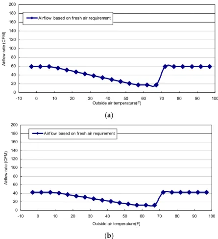
Figure7shows the calculated minimum air flow based on the fresh air requirement at different occupied conditions. The percentage of outside air in an AHU is in the range of 30%–100% of the full outside air intake according to outside air temperature ranges. The determined minimum air flow for the fresh air requirement was 18–60 CFM, and the minimum air flow ratio for the ventilation requirement was 9%–30% during fully occupied conditions.
–
– –
(a)
(b)
Figure 7. Calculated minimum air flow based on fresh air requirement for differen
0 20 40 60 80 100 120 140 160 180 200
-10 0 10 20 30 40 50 60 70 80 90 100
Outside air temperature(F)
A irf lo w ra te (C F M )
Airflow based on fresh air requirement
0 20 40 60 80 100 120 140 160 180 200
-10 0 10 20 30 40 50 60 70 80 90 100
Outside air temperature(F)
A irf lo w ra te ( C F M )
Airflow based on fresh air requirement
3.3. Minimum Air Flow Requirement
The minimum air flow set point can be set so that it equals either the highest air flow rate required by the room design heating load or the minimum rate required for ventilation.
•
Vmin=max(V•min,h,
•
Vmin,v) (21)
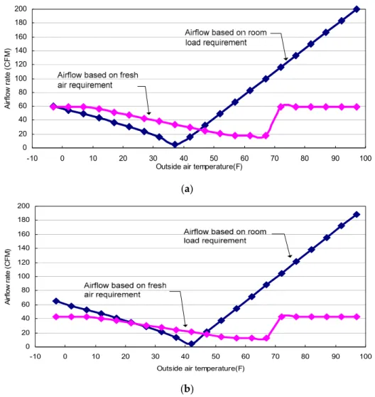
Figure8shows the calculated minimum air flow for room load and fresh air requirements under differing occupied conditions. During fully occupied conditions, the fresh air requirement served as a more critical factor; however, during unoccupied conditions, minimum air flow can generally be determined by the load requirement.
(a)
(b)
Figure 8. Determined minimum air flow for room load requirement and fresh air requirement for
0 20 40 60 80 100 120 140 160 180 200
-10 0 10 20 30 40 50 60 70 80 90 100
Outside air temperature(F)
A
irf
lo
w
ra
te
(C
F
M
)
0 20 40 60 80 100 120 140 160 180 200
-10 0 10 20 30 40 50 60 70 80 90 100
Outside air temperature(F)
A
irf
lo
w
r
a
te
(C
F
M
)
Figure 8. Determined minimum air flow for room load requirement and fresh air requirement for different occupied conditions: (a) fully occupied condition; and (b) 50% occupied condition.
Sustainability2016,8, 1151 11 of 22
(a)
(b)
(c)
Figure 9. Comparison of the air flow between existing fixed minimum air flow and the determi
0 20 40 60 80 100 120 140 160 180 200
-10 0 10 20 30 40 50 60 70 80 90 100
Outside air temperature(F)
A
irf
lo
w
ra
te
(
C
F
M
)
0 20 40 60 80 100 120 140 160 180 200
-10 0 10 20 30 40 50 60 70 80 90 100
Outside air temperature(F)
A
irf
lo
w
ra
te
(C
F
M
)
0 20 40 60 80 100 120 140 160 180 200
-10 0 10 20 30 40 50 60 70 80 90 100
Outside air temperature(F)
A
ir
flo
w
ra
te
(C
F
M
)
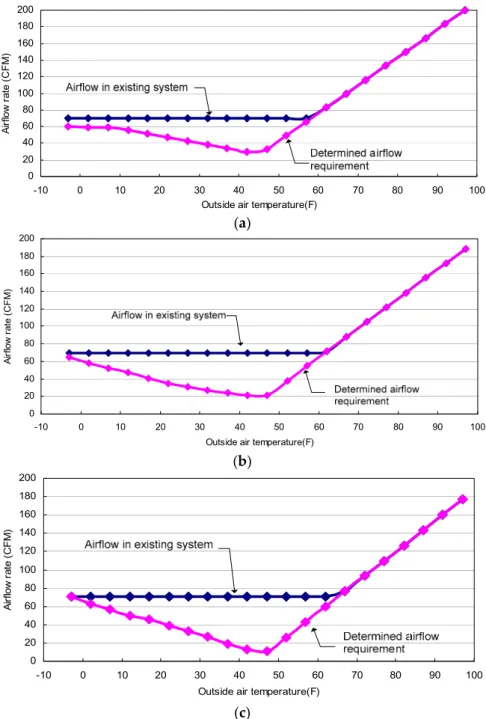
Figure 9.Comparison of the air flow between existing fixed minimum air flow and the determined air flow for different occupied conditions: (a) fully occupied condition; (b) 50% occupied condition; and (c) unoccupied condition.
The air flow range with the fixed minimum air flow and optimal air flow in differing occupied conditions. The range of the optimal air flow was 6% to 35% of the design air flow. The shaded area between the fixed minimum air flow and optimal air flow represents the potential amount of energy saved. This graph reveals that the energy consumption of the optimal minimum air flow can be less than that of the conventional fixed minimum air flow.
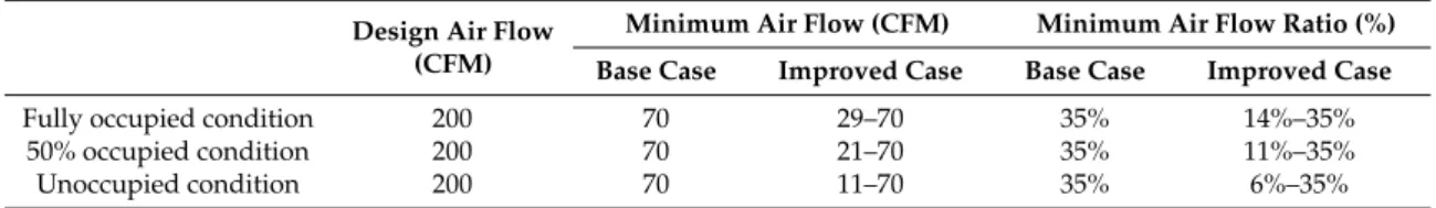
Table 1.Determined minimum air flow for different occupied conditions and its ratio.
Design Air Flow (CFM)
Minimum Air Flow (CFM) Minimum Air Flow Ratio (%)
Base Case Improved Case Base Case Improved Case
Fully occupied condition 200 70 29–70 35% 14%–35%
50% occupied condition 200 70 21–70 35% 11%–35%
Unoccupied condition 200 70 11–70 35% 6%–35%
4. Optimal Terminal Box Control Algorithms
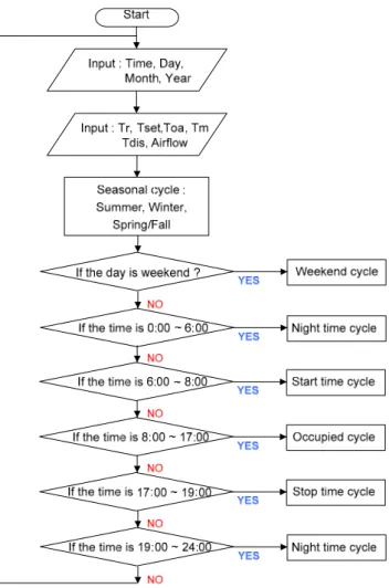
Generally, EMCS achieve energy efficiency by improved the scheduling and operation without sacrificing thermal comfort. EMCS functions can be activated based on the time of year, month and the daily operation of building system. In this study, applicable optimal terminal box control algorithms for EMCS functions integrated with AHUs are developed.
4.1. General Operation Function for an EMCS
➢ Objective: To improve thermal comfort and reduce energy consumption
➢ Definitions:
• Seasonal cycle: summer, winter and spring/fall
• Weekend cycle: the day of the year is a weekend or holiday • Occupied cycle: the day of the year is a weekday
• Nighttime cycle: the terminal box is disabled
• Start/stop time cycle: before and after working hours
➢ Process:
The EMCS can automatically classify what season it is currently, depending on the month. There are three seasonal operation modes: summer, winter and spring/fall. For example, if the month of the year is August, the terminal box goes to summer cooling operation mode.
The EMCS considers whether it is a normal cycle or weekend cycle by the day of the year. If the day of the year is a weekend or holiday, the terminal box goes to the “weekend cycle”. During the weekend cycle, the terminal box is usually disabled based on the room and outside air conditions. During the week, the system goes to the daily normal operation cycle.
Sustainability2016,8, 1151 13 of 22
Figure 10. Figure 10.General terminal box operation cycle. General terminal box operation cycle.
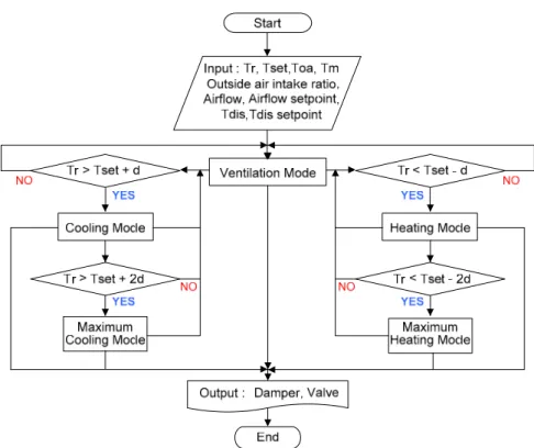
4.2. Occupied Time Operation for EMCS
The most complex operation strategy is the occupied time cycle, when the occupants stay in the room. Occupied period control sequences are the most important and require complex EMC functions because of the effect on occupant thermal comfort. Most of all, HVAC control through EMCS should give thermal comfort to occupants. The system can also save energy with an optimal control sequence. The five modes during the occupied time cycle are as follows:
• Ventilation mode: When the room air temperature is equal to its set point deviation (d), the reheat valve is closed; the air flow set point is maintained by the calculated required fresh air intake. • Cooling mode: When the room air temperature is above its set point deviation (d), the reheat
valve is closed; the room temperature set point is maintained by modulating the air flow between the maximum and minimum values.
• Maximum cooling mode: When the room air temperature is above its set point deviation (2d), the reheat valve is closed; the maximum air flow of this mode is higher than that of cooling mode. • Heating mode: When the room air temperature is below its set point deviation (d), the discharge air
temperature is maintained by modulating the reheat valve between its maximum and minimum set point; the air flow set point is the calculated required ventilation air flow.
• Maximum heating mode: When the room air temperature is below its set point deviation (2d), the air flow is maintained between its maximum and minimum values.
Figure 11. Control algorithms for occupied time operation.
α
α
Figure 11.Control algorithms for occupied time operation.
When the terminal box is enabled, the terminal box is set at the ventilation mode. The air flow rate that satisfies the outside air ventilation requirements can be calculated by Equations (18) and (19). The outside air intake ratio can be derived from the AHU’s control variable.
Under the ventilation mode, the controller checks two conditions: (1) whether the room temperature is higher than its set point deviation (d); and (2) whether the room temperature is lower than its set point deviation (d).
When the first condition is satisfied, the terminal box is switched to the cooling mode. In the cooling mode, the air flow set point varies between the design cooling air flow and required ventilation air flow to maintain the room temperature. During the cooling mode, the room temperature is higher than its set point deviation (2d), and the terminal box is switched to the maximum cooling mode. Set the maximum cooling air flow toαtimes the current design cooling air flow set point. If the room
temperature is lowered, the terminal box is switched from the maximum cooling to the cooling mode. If the room temperature satisfies within its set point deviation (d), the terminal box is switched from cooling mode to ventilation mode. If the second condition is satisfied, the terminal box is switched from the ventilation mode to the heating mode. The heating air flow is set between the required ventilation air flow and design heating air flow to maintain the room temperature. The discharge air temperature has a maximum set point which cannot be more than 15◦F above room temperature, as recommended by ASHRAE Standard 62.1-2004 [15]. If the room temperature is lower than its set point deviation (2d), the terminal box is switched to the maximum heating mode. Set the maximum heating air flow toαtimes the current design heating air flow set point. If the room temperature increases, the
Sustainability2016,8, 1151 15 of 22
Table 2.Summary of operation control variables.
Mode Mode Period Air flow Set Point Discharge Temperature Set Point Maximum Minimum Maximum Minimum
Occupied
Ventilation Tset−d < Tr < Tset + d CFM_ventilation CFM_ventilation Ts Ts Cooling Tr > Tset + d CFM_cooling CFM_ventilation Ts Ts Maximum cooling Tr > Tset + 2d αCFM_cooling CFM_ventilation Ts Ts
Heating Tr < Tset−d CFM_heating CFM_ventilation Tr + 15 Ts Maximum heating Tr < Tset−2d αCFM_heating CFM_ventilation Tr + 15 Ts
Unoccupied Cooling Tr > Tset + 4d CFM_cooling Zero Ts Ts
Heating Tr < Tset−4d CFM_heating Zero Tr + 15 Ts
In current practice, a proportional-only controller can result in as fast a response as an offset controller. If the gain is higher, the response of the control system will also increase, but the higher gain also causes overshoot and hunting. To solve this problem, proportional and integral control is the most common and widely used control method in HVAC systems, although it is difficult to select appropriate proportional and integral gains for multiple control loops. Figure12shows a schematic diagram for an air flow control loop. To maintain the room air temperature set point, the controller calculates the desired air flow set point. The damper modulates to maintain the air flow set point. Figure13shows a schematic diagram for the discharge air temperature control loop. To maintain the room air temperature set point, the controller calculates the desired discharge air temperature set point. The reheating valve modulates to maintain its set point.
−
α −
− α
−
Figure 12. Schematic diagram for air flow control loop.
box
S
P
Q
2Q
S
fan
Figure 12.Schematic diagram for air flow control loop.
−
α −
− α
−
Figure 13. Schematic diagram for discharge air temperature control loop.
Figure 13.Schematic diagram for discharge air temperature control loop.
5. Application
box with hydronic reheat and serve both interior and exterior zones. One typical terminal box, located at the south exterior office room, was chosen in this study to apply the optimal terminal box control sequence. There is normally one person occupying this office; the occupied hours on the weekdays are 8:00 a.m. to 6:00 p.m. The HVAC system operates 24 h a day, 7 days a week. The room air temperature set point is 73◦F and the AHU supply air temp set point is 55◦F. The HVAC system EMCS software (Andover, Omaha, NE, USA) is Andover with Plain English®programming. Table3shows the applied building system information.
Table 3.Building information.
Item Information
EMCS Software Andover Continuum with Plain English®Programming
Zone
Location Purpose
Size
Omaha, Nebraska Office room
Floor area: 215 ft2, Volume: 1550 ft3
People ScheduleNumber Normally one Person during occupied hourOccupied hours (8:00 a.m.–6:00 p.m.)
Operation condition
HVAC system AHU supply air temperature Supply hot water temperature
Room set point
24 h, 7 days working 55 F 140 F
73 F
EMCS control point
AHU Input
Outside air temperature Mixed air temperature Supply air temperature Return air temperature
Terminal box Input
Space room air temperature Discharge air temperature
Air flow rate
Terminal box Output Reheating valve positionDamper position
Terminal box information Type Single-duct pressure independent terminalbox with hydronic reheat coil
5.1. Conventional Terminal Box Control
The type of terminal box in this building is a single-duct pressure independent VAV terminal box with hydronic reheat coil. The existing control sequence is the following. On a call for cooling, air flow will increase as the damper opens towards the fixed maximum air flow set point (250 CFM) to satisfy room air temperature set point. On a call for less cooling, air flow will decrease as the damper closes towards the fixed minimum air flow set point to satisfy the room air temperature set point. With a further call for heat, air flow drops to the minimum air flow set point and the reheat coil valve is modulated to maintain the room air temperature heating set point. The fixed minimum air flow set point (125 CFM) is based on the design heating load air flow. The terminal box operates 24/7 to maintain the room air temperature set point. Figure14shows the conventional terminal box control sequence.
Sustainability2016,8, 1151 17 of 22
as shown in Figure16. Therefore, the terminal boxes need to optimize the control sequence according to building operation conditions.
Figure 14. Conventional terminal box control sequence. Figure 14.Conventional terminal box control sequence.
Figure 15. Temperature trending data for conventional control.
0 20 40 60 80 100 120 140 160 4/8/2007 4/8/2007 3:00:00 AM 4/8/2007 6:00:00 AM 4/8/2007 9:00:00 AM 4/8/2007 12:00:00 PM 4/8/2007 3:00:00 PM 4/8/2007 6:00:00 PM 4/8/2007 9:00:00 PM 4/9/2007 Time T e m p e ra tu re ( F ) Disch Temp Supply Temp Room Temp Oa Temp
Figure 15.Temperature trending data for conventional control.
Figure 16. Air flow trending data for conventional control.
0 20 40 60 80 100 120 140 160 4/8/2007 4/8/2007 3:00:00 AM 4/8/2007 6:00:00 AM 4/8/2007 9:00:00 AM 4/8/2007 12:00:00 PM 4/8/2007 3:00:00 PM 4/8/2007 6:00:00 PM 4/8/2007 9:00:00 PM 4/9/2007 Time T e m p e ra tu re ( F ) 0 50 100 150 200 250 300 A irf lo w (C F M ) Room Temp Oa Temp Sup airflow Fresh airflow
5.2. Improved Terminal Box Control
With the new terminal box control sequence, the EMCS can automatically check the operation cycle based on the previous optimal control algorithm such as the seasonal operation cycles, normal cycle or weekend cycle and daily occupied time operation cycle. The outside fresh air intake ratio for the minimum ventilation mode can be calculated by Equations (17) and (18) from the AHU control input. To maintain room air temperature, the variable air flow and discharge temperature set point can be calculated by the previous control loop. Finally, the damper and valve modulate to maintain the room air temperature set point.
5.2.1. Stability of Room Air Temperature Control
An analysis of the stability of the room air temperature control in an actual system shows that the range of room air temperature is 70.9◦F–73.6◦F, discharge air temperature is 55.6◦F–86.9◦F and supply air flow is 25.6–75.9 CFM during occupied time as shown in Figures17and18. The room air temperature is able to maintain the set point (73◦F) within control deviation. The average room air temperature is lower than its set point. During the occupied period, the AHU’s outside air intake is at minimum condition and the supply air flow set point is higher than the economizer season air flow set point to maintain the fresh air requirement as shown in Figure18. During the unoccupied period, the lowest room air temperature is 68.7◦F; however, the system is maintained in a disabled condition because the room air temperature cannot reach the unoccupied operation heating set point (Tr < Tset−4d). If the outside air condition is extremely cold or hot during the winter or summer season, the system will respond quickly based on the room air conditions. During the start time, the system tries to catch the room air temperature set point before occupancy. Therefore, it is assumed that there is proper and stable room air temperature control.
−
Figure 17. Temperature trending data of improved control.
0 20 40 60 80 100 120 140 160
9/27/07 12:00 AM
9/27/07 3:00 AM
9/27/07 6:00 AM
9/27/07 9:00 AM
9/27/07 12:00 PM
9/27/07 3:00 PM
9/27/07 6:00 PM
9/27/07 9:00 PM
9/28/07 12:00 AM Time
T
e
m
p
e
ra
tu
re
(
F
)
Disch Temp SupplyAir Temp Room Temp Oa Temp
Figure 17.Temperature trending data of improved control.
5.2.2. Thermal Comfort
Sustainability2016,8, 1151 19 of 22
likely to be satisfied if the ventilation results in indoor CO2concentrations less than 700 ppm above the outdoor air concentration, which is representative of delivery rates of outside air. Therefore, it is assumed that any IAQ problems due to reduction of the minimum air flow set point will not happen.
Figure 18. Air flow trending data of improved control.
0 20 40 60 80 100 120 140 160 9/27/07 12:00 AM 9/27/07 3:00 AM 9/27/07 6:00 AM 9/27/07 9:00 AM 9/27/07 12:00 PM 9/27/07 3:00 PM 9/27/07 6:00 PM 9/27/07 9:00 PM 9/28/07 12:00 AM Time T e m p e ra tu re ( F ) 0 50 100 150 200 250 300 A irf lo w (C F M ) Room Temp Oa Temp Supply airflow Fresh airflowFigure 18.Air flow trending data of improved control.
5.2.3. Potential Energy Savings
The reheat energy savings can be considered as the reheat energy consumption required to heat the reduced air flow from the supply air temperature to the room temperature. The reheating coil energy consumption can be estimated based on Equation (22).
The cooling energy savings equals the cooling energy consumption to cool the reduced air flow from the room conditions to the supply air condition. When the room moisture production is neglected, the potential cooling energy consumption equals the potential reheat energy consumption. The cooling energy consumption can be estimated based on Equation (23) when the outside air temperature is higher than the supply air temperature. When the outside air temperature is lower than the supply air temperature, mechanical cooling can be eliminated by using an economizer. Therefore, the potential cooling energy savings is zero when an economizer is used. If an economizer is not used, the reduced air flow can decrease the cooling energy consumption even when the outside air temperature is lower than the supply air temperature.
When the impact of the fan efficiency decrease is neglected, the potential fan power savings can be estimated based on Equation (24). When the supply fan air flow is reduced, the supply fan speed should be reduced and the total fan power will be dropped. Therefore, significant fan power should be saved. With proper static pressure control from the air handling unit, the rooms receive adequate cooling air flow and do not overwhelm the fan.
∆Erh=m• ·Cp·(αmin′−αmin)·(Tr−Ts) (22)
∆Ec=m• ·Cp·(αmin′−αmin)(hr−hs) (23)
∆Ef =
•
with an improved control sequence. The thermal energy consumption with improved minimum air flow is less than that with conventional minimum air flow. Based on the trending data, the reheating energy cannot be compared between conventional and improved control sequences because the outside air conditions are not the same. However, reduction of supply air flow and discharge air temperature should save fan power, cooling and heating energy consumption by optimal terminal box control algorithms.
6. Conclusions
In this study, applicable optimal terminal box control algorithms for EMCS are suggested. To improve the conventional terminal box control sequence, dynamic models were analyzed, optimal control algorithms were developed, and the developed EMCS algorithms were then applied to an actual building. The terminal box energy consumption and thermal performance were compared between conventional and improved control. The results are as follows.
(1) In conventional control, the room temperature could not maintain its set point because the minimum air flow supplies an inadequate air flow for a conditioned space without considering building operation conditions. The minimum air flow is higher than required, which often leads to significant simultaneous heating and cooling, in addition to excessive fan power.
(2) Improved control can stably maintain the set room air temperature and reduce energy consumption, compared to conventional control. Measurements of CO2levels show there is no indoor air quality problem when the minimum air flow set point is reduced.
(3) In energy measured results, the thermal energy consumption with improved control is less than that with the conventional control. Therefore, if developed EMCS control algorithms are applied, a terminal box can reduce thermal energy.
Acknowledgments:This research was supported by a grant (16AUDP-B079104-03) from Architecture & Urban Development Research Program funded by Ministry of Land, Infrastructure and Transport of Korean government.
Author Contributions:All authors contributed to this work. Yoon-Bok Seong performed the result analysis and wrote the major part of this article. Young-Hum Cho was responsible for this article and gave conceptual advice.
Conflicts of Interest:The authors declare no conflict of interest.
Nomenclature
Tr Room air temperature,◦F
Tout outside air temperature,◦F
Tad,j interior air temperature,◦F
qi internal heat gains, Btu/hr
•
mv mass flow rate of ventilation air, lbm/h
ρ standard air density, lbm/ft3
V volume of room air mass, ft3
Ca specific heat of air, Btu/lbm◦F
Ui heat transfer coefficient of exterior wall, Btu/lbm ft2◦F Uj heat transfer coefficient of interior wall, Btu/lbm ft2◦F
Ai area of exterior wall, ft2
Aj area of interior wall, ft2
Ts steady state supply air temperature,◦F
Td,s steady state discharge air temperature,◦F
Ts,w steady state supply water temperature,◦F
Tr,w steady state return water temperature,◦F •
ma mass flow rate of air, lbm/h
•
Sustainability2016,8, 1151 21 of 22
Cw=m•wcp,w specific heat of water, Btu/lbm◦F Ca=m•acp,a specific heat of air, Btu/lbm◦F
Cmin=Minimum(Ca,Cw) equal toCaorCw, whichever is smaller. Cmax=Maximum(Ca,Cw) equal toCaorCw, whichever is bigger.
Cr= CCminmax heat capacity ratio
NTU= CU A
min number of transfer units
ε=1−exphNTUCr0.22 n
exph−Cr(NTU)0.78
i
−1oiheat exchanger effectiveness with both fluids unmixed
TD,d,s dynamic discharge air temperature,◦F TD,r,w dynamic return water temperature,◦F
tcoil coil time constant
Pa,i Inlet air pressure
Pa,o outlet air pressure
ka air flow resistance coefficient
ma air flow rate
Pw,i Inlet water pressure
Pw,o outlet water pressure
kw water flow resistance coefficient
mw water flow rate
• Vf
air volumetric flow rate for fresh air requirement, ft3/min
αoa AHU outside air intake ratio, %
Sbox terminal box air flow resistance
∆Ef fan power, kw
hr room enthalpy, Btu/lbm
hs supply enthalpy, Btu/lbm
αmin′ minimum air flow ratio in conventional conditions
αmin minimum air flow ratio in improved conditions
αs supply air flow ratio
ηf,d fan efficiency
Ps,d the static pressure set point, in.wg
References
1. Elovitz, D.M. Minimum outside air control method for VAV systems.ASHRAE Trans.1995,101, 613–618. 2. Krakow, K.I. Economizer control.ASHRAE Trans.2000,106, 13–25.
3. Ke, Y.P. Optimized supply air temperature (SAT) in variable-air-volume (VAV) systems.Energy Int. J.1997,
22, 601–614. [CrossRef]
4. Zaheer-uddin, M. VAV system model to simulate energy management control functions: Off-normal operation and duty-cycling.Energy Convers. Manag.1994,35, 917–932. [CrossRef]
5. Engdahl, F.; Johansson, D. Optimal supply air temperature with respect to energy use in a variable air volume system.Energy Build.2004,36, 205–218. [CrossRef]
6. Wei, G.; Claridge, D.E.; Liu, M. Optimize the Supply Air Temperature Reset Schedule for a Single Duct VAV system. In Proceedings of the Twelfth Symposium on Improving Building Systems in Hot and Humid Climates, San Antonio, TX, USA, 15–17 May 2000; pp. 154–157.
7. Nassif, N.; Moujaes, S. A new operating strategy for economizer dampers of VAV system.Energy Build.2008,
40, 289–299. [CrossRef]
8. Taylor, S.T.; Stein, J. Sizing VAV Boxes.ASHRAE J.2004,46, 30–35.
9. Cho, Y.; Liu, M. Minimum air flow reset of single duct VAV terminal boxes. Build. Environ. 2009, 44, 1876–1885. [CrossRef]
10. Cho, Y.; Liu, M. Correlation between minimum air flow and discharge air temperature.Build. Environ.2010,
45, 1601–1611. [CrossRef]
12. Kim, H.; Kang, S.; Cho, Y. A study on the control method without stratification of single duct VAV terminal units.J. Asian Arch. Build. Eng.2015,14, 467–474. [CrossRef]
13. Taylor, S.; Stein, J.; Paliago, G.; Cheng, H. Dual maximum VAV box control logic.ASHRAE J.2012,54, 16–24. 14. Zhang, B.; Li, Y.; Lau, J.; Liu, M. Demand control ventilation: Influence of terminal box minimum air flow
setting on system energy use.Energy Build.2014,79, 173–183. [CrossRef]
15. American Society of Heating, Refrigerating and Air-Conditioning Engineers (ASHRAE).Ventilation for Acceptable Indoor Air Quality (IAQ); ASHRAE Standard 62.1-2004; ASHRAE: Atlanta, GA, USA, 2004.